manuals.online logo
Brands
  1. Home
  2. •
  3. Brands
  4. •
  5. Sony
  6. •
  7. Digital Camera
  8. •
  9. Sony XCST70 User manual

Sony XCST70 User manual

70 XC-ST70/ST70CE/ST50/ST50CE/ST51/ST51CE/ST30/ST30CE
Digital Video Camera
Intelligent
XCI
XC (Non-TV Format)
XC (TV Format)
Accessories
XCL XCGXCD
Color Camera Module
Color PTZ Camera
FCBEVI
Analog Video Camera
CCD
VIDEO CAMERA MODULE
XC-ST50
57.5
50 ±0.513
26±0.3
29
4-M3 depth 4
8
44
65.5
13
26 ±0.3
2-M3 depth 4
BLACK-and-WHITE VIDEO CAMERA MODULE
Unit: mm
XC-ST70/ST70CE
XC-ST50/ST50CE
XC-ST51/ST51CE
XC-ST30/ST30CE
Camera body of all XC-ST models
*1 :XC-ST70/ST70CE
*2 :XC-ST50/ST50CE/ST51/ST51CE
*3 :XC-ST30/ST30CE
Outline
The XC-ST Series cameras incorporate the latest CCD and
signal processing technologies into a compact black and
white camera module. A new external trigger design allows
the electronic shutter speed to be freely specied by the
width of an external trigger pulse or by a switch setting on
the rear panel of the camera. These cameras are also
user-friendly, with all switch settings located on the rear
panel. Moreover, the XC-ST Series have the exact same
dimensions, simplifying space requirements and making
it easy to interchange them if necessary. These features,
along with high picture quality and high shock and vibration
tolerance make the XC-ST Series cameras ideal for
demanding machine vision applications.
Compact camera adaptor■
DC-700/700CE•
12-pin camera cable (CE standard)■
CCXC-12P02N (2 m)•
CCXC-12P05N (5 m)•
CCXC-12P10N (10 m)•
CCXC-12P25N (25 m)•
Tripod adaptor■
VCT-ST70I•
Accessories
XC-ST70•
Wavelength (nm)
(Lens characteristics and light source characteristics excluded.)
Relative sensitivity
(Typical Values)
Spectral Sensitivity Characteristics
Dimensions
XC-ST70/ST70CE: 2/3-type IT CCD■
XC-ST51/ST51CE/ST50/ST50CE: 1/2-type IT CCD■
XC-ST30/ST30CE: 1/3-type IT CCD■
Small and lightweight: 44 (W) × 29 (H) × 57.5 (D) mm,■
Approx. 110 g
Flexible trigger shutter functions■
High sensitivity■
XC-ST51/ST51CE: 0.2 lx (F1.4)
XC-ST70/ST70CE/ST50/ST50CE/ST30/ST30CE:
0.3 lx (F1.4)
2:1 interlaced/non-interlaced (during external sync input)■
High S/N ratio : 60 dB (XC-ST70/ST50/ST51)■
: 58 dB (XC-ST30)
Electronic shutter function (1/100 sec to 1/10,000 sec)■
Synchronization: internal/external (HD/VD, VS)■
Frame/Field exposure■
Restart/Reset function■
High shock and vibration tolerant■
Features
1/2
Type
CCD
1/3
Type
CCD
C
Lens Mount
VS
Output
HD VD
External Sync
Long
Exposure
Normal
Shutter
Mode 1
(Non-Reset Mode)
External
Trigger Shutter
Mode 2
(Non-Reset Mode)
External
Trigger Shutter
*1 *2 *3
2/3
Type
CCD
Restart
Reset
TV
Format
Output
VS
External Sync
Connection Diagram
P100
0
400 500 600 700 800 900 1000
0.2
0.4
0.6
0.8
1.0
71
XC-ST70/ST70CE/ST50/ST50CE/ST51/ST51CE/ST30/ST30CE
Digital Video Camera Intelligent
XCI XC (Non-TV Format) XC (TV Format) Accessories
XCG XCLXCD
Color Camera Module
Color PTZ Camera
FCB EVI
Analog Video Camera
1Lens mount (C-mount)
Attach any C-mount lens or other optical equipment.
The lens must not project more than 10 mm from the lens mount.
2Reference holes (at the top)
These precision screw holes are for locking the camera module.
Locking the camera module using these holes secures the optical
axis alignment.
3Reference screw holes/Tripod screw holes (at the bottom)
These precision screw holes are for locking the camera module.
Locking the camera module using these holes secures the optical
axis alignment.
You can install the camera on a tripod. To install on a tripod,
you will need to install the VCT-ST70I tripod adaptor using the
reference holes on the bottom of the camera.
400 500 600 700 800 900 1000
0
0.2
0.6
0.4
0.8
1.0
XC-ST50/XC-ST51/XC-ST30•
Wavelength (nm)
(Lens characteristics and light source characteristics excluded.)
Relative sensitivity
(Typical Values)
Location and Function of Parts and Controls
1Lens mount (C-mount)
2Reference holes
3Reference screw holes/
Tripod screw holes
XC-ST70 XC-ST50 XC-ST51 XC-ST30
XC-ST70CE XC-ST50CE XC-ST51CE XC-ST30CE
Image device 2/3-type IT CCD 1/2-type IT CCD 1/3-type IT CCD 2/3-type IT CCD 1/2-type IT CCD 1/3-type IT CCD
Signal system EIA CCIR
Effective picture elements (H) × (V) 768 × 494 752 × 582
Effective lines (H) × (V) 752 × 485 736 × 575
Cell size (H) × (V)
11.6
μ
m × 13.5
μ
m
8.4
μ
m × 9.8
μ
m
6.35
μ
m
×
7.4
μ
m
11.6
μ
m × 11.2
μ
m
8.6
μ
m × 8.3
μ
m
6.5
μ
m
×
6.25
μ
m
Horizontal frequency 15.734 kHz 15.625 kHz
Vertical frequency 59.94 Hz 50 Hz
Lens mount C mount
Sync system Internal/External
External Sync system input/output*1 HD/VD (HD/VD level: 2 V to 5 Vp-p)
External Sync frequency ±1% (in horizontal sync frequency), VS
Jitter less than ±20 nsec (external horizontal frequency)
Scanning system 2:1 Interlaced
Video output 1.0 Vp-p, negative, 75 Ω unbalanced
Horizontal resolution 570 TV lines 560 TV lines
Sensitivity 400 lx, F8
(γ= ON, 0 dB)
400 lx, F11
(γ= ON, 0 dB)
400 lx, F5.6
(γ= ON, 0 dB)
400 lx, F8
(γ= ON, 0 dB)
400 lx, F11
(γ= ON, 0 dB)
400 lx, F5.6
(γ= ON, 0 dB)
Minimum illumination 0.3 lx
(F1.4, AGC ON)
0.2 lx
(F1.4, AGC ON)
0.3 lx
(F1.4, AGC ON)
0.3 lx
(F1.4, AGC ON)
0.2 lx
(F1.4, AGC ON)
0.3 lx
(F1.4, AGC ON)
S/N ratio 60 dB 56 dB 58 dB 54 dB
Gain AGC/Fixed/Manual (adjustable on the rear panel)
Gamma ON/OFF (adjustable on the rear panel)
Normal shutter 1/100 sec to 1/10,000 sec 1/120 sec to 1/10,000 sec
External trigger shutter 1/4 sec to 1/10,000 sec 1/4 sec to 1/8,000 sec
Power requirements DC 12 V (10.5 V to 15 V)
Power consumption 2.1 W 2.0 W 1.9 W 2.1 W 2.0 W 1.9 W
Dimensions 44 (W) × 29 (H) × 57.5 (D) mm (not including projecting parts)
Mass 105 g 110 g 105 g 110 g
Operating temperature/humidity −5˚C to +45˚C / 20% to 80% (no condensation)
Storage temperature/humidity −30˚C to +60˚C / 20% to 95% (no condensation)
Performance guarantee temperature 0˚C to 40˚C
Vibration resistance 10 G (20 Hz to 200 Hz 20 minutes for each direction–x, y, z)
Shock resistance 70 G
MTBF 70,600 hours (Approx. 8.1 years)
Regulatory compliance UL6500, FCC/ICES-003 : Class B, CE : EN61326, AS/NZ : EN61326
Supplied accessories Lens mount cap (1), Operating instructions (1)
Specifications
Lens mount shoulder
10 mm or less
Note
*1 Automatic switching in response to the presence of an input signal when the switch on the rear panel is set to EXT.
The values for mass and dimension are approximate.
72 XC-ST70/ST70CE/ST50/ST50CE/ST51/ST51CE/ST30/ST30CE
Digital Video Camera
Intelligent
XCI
XC (Non-TV Format)
XC (TV Format)
Accessories
XCL XCGXCD
Color Camera Module
Color PTZ Camera
FCBEVI
Analog Video Camera
This mode provides continuous video output with the electronic
shutter selected by switches to capture a high-speed moving
object clearly.
Normal shutter speed settings
There are two shutter types: normal shutter and external trigger
shutter. Select them with the DIP switches on the rear panel.
About the Electronic Shutter
Rear panel
Switches 1 to 4: Shutter speed
Switch 5: Potential accumulation mode
Switches 6 to 8: Restart reset/External trigger shutter mode switch
* If you set the mode to ickerless, the positions of DIP switches 1 to 3 are optional.
Normal Shutter
Note
The DIP switch 5 position is optional. (The eld setting is
recommended.) The eld setting can obtain a sensitivity that is
twice that of the frame setting.
(Unit: second)
Shutter
OFF 1/125 1/250 1/500 1/1000
1/2000 1/4000 1/10000
Flickerless*
1/100 (EIA)
1/120 (CCIR)
Rear panel
Connector Pin Assignments
DIP switches
* Common ground for pins 7, 10, and 11
Rear Panel
Factory Mode Settings of Rear Panel
1) This unit is shipped from the factory with the GAIN switch being set to F (x), so the Manual
gain control knob is not operative unless the switch setting is changed. When the GAIN switch
is set to M (manual), you can rotate this knob to adjust gain over the range 0 to 18 dB.
No. Switch
Factory setting mode
1HD/VD signal input/output switch EXT
3γcompensation ON/OFF switch OFF
4GAIN switch F
5Manual gain control – 1)
6Shutter speed/Mode
setting DIP switches
Shutter speed (bits 1 – 4)
OFF
(All S/W are left
side)
Potential accumulation mode (bit 5)
Restart reset/External trigger shutter
mode switch (bits 6 – 8)
775  termination switch ON
8TRIG polarity switch +
1HD/VD signal input/output switch
Set the switch to INT to output HD/VD signals from the camera
module. Set the switch to EXT to input HD/VD signals from an
external unit. (Factory setting: EXT)
2VIDEO OUT (Video signal output) connector (BNC)
You can use this connector for video signal output from the
camera module.
3γcompensation ON/OFF switch
Turn on this switch for g compensation. (Factory setting: OFF)
4GAIN switch
This switch selects AGC (A), xed gain (F), or manual gain control
(M). (Factory setting: F)
5Manual gain control
Adjust the gain using this control. GAIN switch 4 must have been
set to M (Manual).
6Shutter speed/Mode setting DIP switch
1Shutter speed (bits 1 to 4)
Set an appropriate shutter speed. (Factory setting: Shutter off)
2
High-rate scan mode switch (bit 5)
Factory setting: FRAME
3
Restart reset/External trigger shutter mode switch (bits 6 to 8)
Factory setting: Normal
Note
Do not use any other settings for Restart reset/External trigger•
shutter mode except those shown on the next page. Using other
settings may cause the camera to malfunction.
If you set the External trigger shutter mode, set 0 in bits 1 to 4.•
775 Ω termination switch
Turn off if you do not terminate. (Factory setting: ON)
8TRIG polarity switch
Select + or – according to the trigger pulse input from an external
unit. (Factory setting: +)
9DC IN/SYNC (DC power input/sync signal I/O) connector
(12-pin)
Connect a CCXC-12P05N camera cable to this connector the
+12 V DC power supply and the video signal output from the
camera module. When a sync signal generator is connected to this
connector, the camera module is synchronized with the external
sync signals.
1
2
3
4
5
6
7
8
9
Pin
No.
Camera sync
output
External mode
(VS)
External mode
(VS) Restart/Reset External
trigger shutter
1Ground Ground Ground Ground Ground
2+12 V DC +12 V DC +12 V DC +12 V DC +12 V DC
3
Video output (Ground) Video output (Ground) Video output (Ground) Video output (Ground) Video output (Ground)
4
Video output (Signal) Video output (Signal) Video output (Signal) Video output (Signal) Video output (Signal)
5
HD output (Ground) HD input (Ground)
—
HD input (Ground) HD input (Ground)
6
HD output (Signal) HD input (Signal)
—
HD input (Signal) HD input (Signal)
7
VD output (Signal)
VD input (Signal) VS input (Signal)
Reset (Signal)
VD input (Signal)
8—————
9—————
10————
WEN output (Signal)
11————
Trigger pulse input (Signal)
12
VD output (Ground)
VD input (Ground) VS input (Ground)
Reset (Ground) Reset (Ground)*
DIP Switches on the Rear Panel
73
XC-ST70/ST70CE/ST50/ST50CE/ST51/ST51CE/ST30/ST30CE
Digital Video Camera Intelligent
XCI XC (Non-TV Format) XC (TV Format) Accessories
XCG XCLXCD
Color Camera Module
Color PTZ Camera
FCB EVI
Analog Video Camera
The Restart/Reset function extends the CCD accumulation time,
resulting in highly sensitive image capture. This function is effective
when you cannot gain satisfactory sensitivity under normal operating
conditions, or when you want to observe the trail of a moving object.
Extend the VD interval (T) between external VD pulses.
Long Exposure
Sample input timing chart 1
Continuous signal: 15.734 kHz (XC-ST51/ST50/ST30) Allowable frequency value ±1%,
15.625 kHz (XC-ST51CE/ST50CE/ST30CE) Allowable frequency value ±1%
VD interval (T): 262.5 H or more (XC-ST51/ST50/ST30) and less than 1 second (Recommended),
312.5 H or more (XC-ST51CE/ST50CE/ST30CE) and less than 1 second (Recommended)
Four or more VD pulses are required.
Exposure time for the Odd eld
Exposure time for the Even eld
Frame Accumulation (Factory setting)
Video output
Odd and even elds are determined by the phase of the EXT HD/VD signal input from the outside.
Invalid image Valid frame image
Odd image Even image
To Set Restart/Reset Mode
The information on one screen can be extracted
at any time by externally inputting Restart/
Reset signals (HD/VD). To enter this mode, set
the trigger shutter switches (6 to 8) on the rear
panel of the camera as shown in the gure
below.
The Reset/Restart mode is especially effective
for frame image output with long exposure or a
strobe light.
Restart/Reset
DIP switches
Inputting an external trigger pulse enables the camera to capture
fast-moving objects clearly with precise timing.
Set DIP switches 6, 7, and 8 on the rear panel to Mode 1 or Mode 2.
When you set the trigger pulse width to 1/3 of a second or more, the
output signal changes to the normal VIDEO signal.
There are two modes for the timing in which video signals are
obtained.
Mode 1 (Non-reset mode)•
In this mode, a video signal synchronized with a VD signal is
output after a trigger pulse is input.
– The video signal is synchronized with the external VD signal
when an external HD/VD signal is input.
– The video signal is synchronized with an internal VD signal when
no external HD/VD signal is input.
Mode 2 (Reset mode)•
In this mode, an internal VD is reset, then a video signal is output
a certain period of time after trigger pulse input.
External Trigger Shutter
To Set the External Trigger Shutter
There are two ways to set the shutter speed.
Using the DIP switches on the rear panel•
For shutter speeds, see the following table.
The DIP switch 5 position is optional. (The eld setting is
recommended.) The eld setting can obtain a sensitivity that is
twice that of the frame setting.
Mode 2 (Reset mode)
(Unit: second)
1/100
(EIA)
1/120
(CCIR)
1/125
1/10000
(EIA)
1/8000
(CCIR)
1/250 1/500
1/1000 1/2000 1/4000
1/100
(EIA)
1/120
(CCIR)
1/125
1/10000
(EIA)
1/8000
(CCIR)
1/250 1/500
1/1000 1/2000 1/4000
(Unit: second)
The DIP switch 5 position is optional. (The eld setting is•
recomended.) The eld setting can obtain a sensitivity that is
twice that of the frame setting.
If you input another trigger pulse before the video signal output•
for the previous trigger pulse is completely output, an incorrect
video signal will be output.
Using trigger pulse width•
Set all DIP switches (1 to 4 on the rear panel) to 0.
You can obtain an arbitrary shutter speed by setting the trigger
pulse width within the range of 2
μ
s to 250 ms.
Exposure time = Trigger pulse width + 97
μ
s (EIA)
Trigger pulse width + 120
μ
s (CCIR)
Mode 1 (Non-reset mode) Mode 2 (Reset mode)
Specifications of trigger pulse
When using a trigger pulse like shown below, set the TRIG•
polarity selector switch on the rear panel to + :
0 V to 0.6 V
2 V to 5.0 V
2 μs to 1/4 sec *1
*1If you set the trigger pulse with the DIP switches, use the 100
μ
s to 1/4 sec pulse width.
When using a trigger pulse like shown below, set the TRIG•
polarity selector switch on the rear panel to - :
Input impedance: 10 k or more.•
The voltage and pulse width used are measured at pin 11 of a 12-pin multi-connector on•
the rear panel.
0 V to 2.0 V
4.0 V to 5.0 V
2 μs to 1/4 sec
Mode 1 (Non-reset mode)
Note
Note
EXT HD
TTT
EXT VD
Other manuals for XCST70

3

This manual suits for next models

7

Other Sony Digital Camera manuals

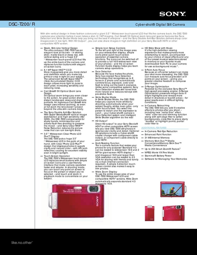
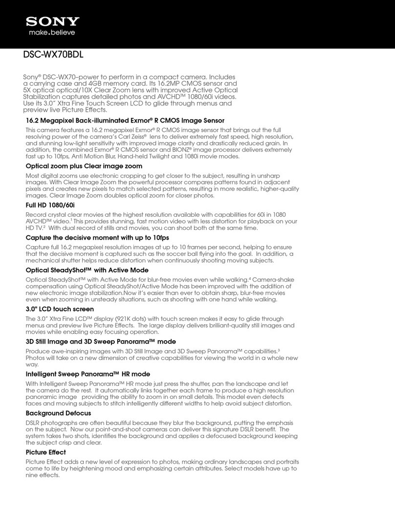
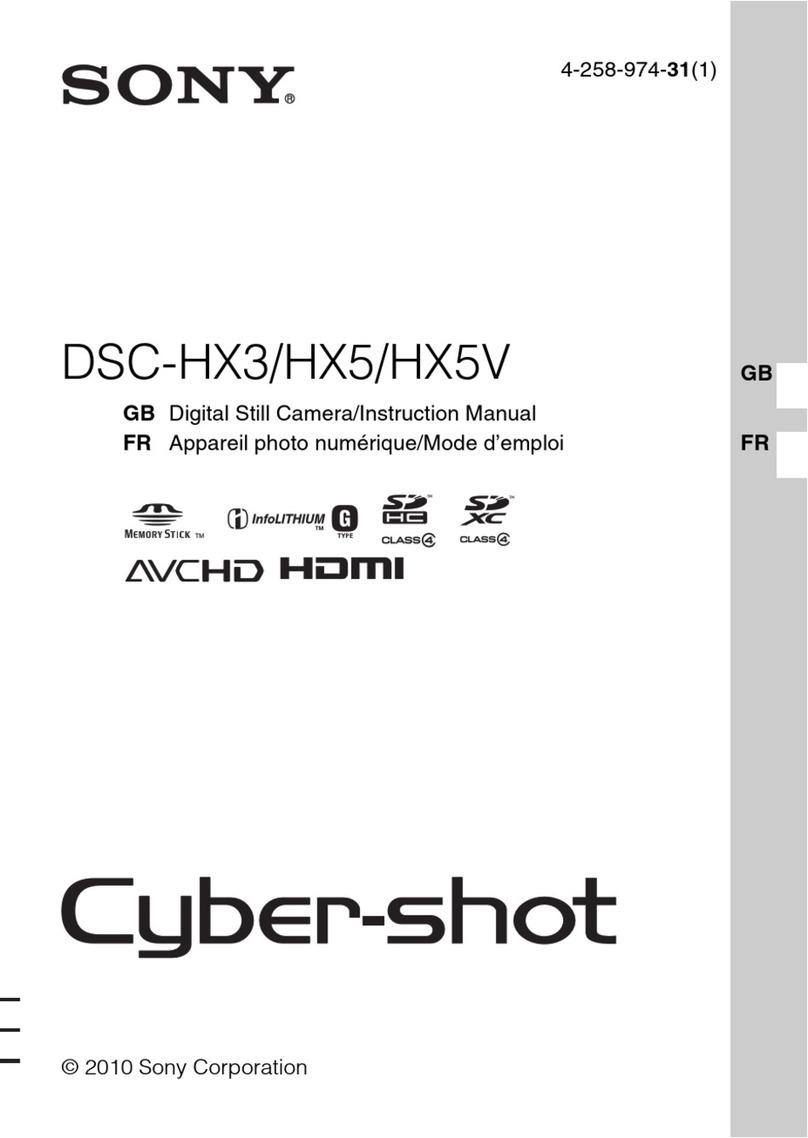
Sony Cyber-shot DSC-HX5 User manual

Sony

Sony Cyber-shot DSC-HX5 User manual

Sony Cyber-shot DSC-W30 User manual

Sony

Sony Cyber-shot DSC-W30 User manual

Sony ILCE-5000L/W User manual

Sony

Sony ILCE-5000L/W User manual

Sony Cyber-shot DSC-S600 User manual

Sony

Sony Cyber-shot DSC-S600 User manual

Sony Cyber-shot DSC-H400 User manual

Sony

Sony Cyber-shot DSC-H400 User manual

Sony DSC-W220/B User manual

Sony

Sony DSC-W220/B User manual

Sony Cyber-shot DSC-W100 Operating instructions

Sony

Sony Cyber-shot DSC-W100 Operating instructions

Sony Cyber-shot DSC-T1 User manual

Sony

Sony Cyber-shot DSC-T1 User manual

Sony DSC-W150/N User manual

Sony

Sony DSC-W150/N User manual

Sony DSC-P71 - Cyber-shot Digital Still Camera User manual

Sony

Sony DSC-P71 - Cyber-shot Digital Still Camera User manual

Sony DSC-TX9 Cyber-shot® User manual

Sony

Sony DSC-TX9 Cyber-shot® User manual

Sony DSC-H7 Cyber-shot® User manual

Sony

Sony DSC-H7 Cyber-shot® User manual

Sony Cybershot,cyber-shot dsc-w570 User manual

Sony

Sony Cybershot,cyber-shot dsc-w570 User manual

Sony Cyber-shot DSC-T900 User manual

Sony

Sony Cyber-shot DSC-T900 User manual

Sony A6300 User manual

Sony

Sony A6300 User manual

Sony Cyber-shot DSC-S600 User manual

Sony

Sony Cyber-shot DSC-S600 User manual

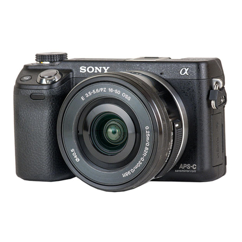
Sony alpha ILCE-3000 User manual

Sony

Sony alpha ILCE-3000 User manual

Sony Multi Functional Digital Camera User manual

Sony

Sony Multi Functional Digital Camera User manual

Sony DSLR-A300/A350 User manual

Sony

Sony DSLR-A300/A350 User manual

Sony ILCE-6500 User manual

Sony

Sony ILCE-6500 User manual

Sony Cyber-shot DSC-H70 Installation instructions manual

Sony

Sony Cyber-shot DSC-H70 Installation instructions manual

Sony Cyber-shot DSC-S600 User manual

Sony

Sony Cyber-shot DSC-S600 User manual

Sony DSC-P92 - Cyber-shot Digital Still Camera User manual

Sony

Sony DSC-P92 - Cyber-shot Digital Still Camera User manual

Sony DSLR-A100 Operating instructions

Sony

Sony DSLR-A100 Operating instructions

Popular Digital Camera manuals by other brands

HP SW450 user manual

HP

HP SW450 user manual

Pentatech DF270K operating instructions

Pentatech

Pentatech DF270K operating instructions

Canon EOS-1D parts catalog

Canon

Canon EOS-1D parts catalog

Liquid Image Hydra HD 720P UDCM 305 user manual

Liquid Image

Liquid Image Hydra HD 720P UDCM 305 user manual

FujiFilm FinePix A201 Service guide

FujiFilm

FujiFilm FinePix A201 Service guide

Speco CVC-575BL Specifications

Speco

Speco CVC-575BL Specifications

Olympus CAMEDIA C-5500 Sport Zoom quick start guide

Olympus

Olympus CAMEDIA C-5500 Sport Zoom quick start guide

BenQ LH500 Series user manual

BenQ

BenQ LH500 Series user manual

Panasonic LUMIX DMC-GM5K Basic owner's manual

Panasonic

Panasonic LUMIX DMC-GM5K Basic owner's manual

Canon BP-511 instructions

Canon

Canon BP-511 instructions

EXTREME CCTV WZ Series installation guide

EXTREME CCTV

EXTREME CCTV WZ Series installation guide

Nikon COOLPIX S3500 Reference manual

Nikon

Nikon COOLPIX S3500 Reference manual

Samsung Pro 815 Service manual

Samsung

Samsung Pro 815 Service manual

Olympus AZ-220 WIDE ZOOM instructions

Olympus

Olympus AZ-220 WIDE ZOOM instructions

Nikon F 100 instruction manual

Nikon

Nikon F 100 instruction manual

Vivitar Vivicam 25 owner's manual

Vivitar

Vivitar Vivicam 25 owner's manual

Olympus E-5 Manuel d'instructions

Olympus

Olympus E-5 Manuel d'instructions

Minox DC 2111 user guide

Minox

Minox DC 2111 user guide

manuals.online logo
manuals.online logoBrands
  • About & Mission
  • Contact us
  • Privacy Policy
  • Terms and Conditions

Copyright 2025 Manuals.Online. All Rights Reserved.