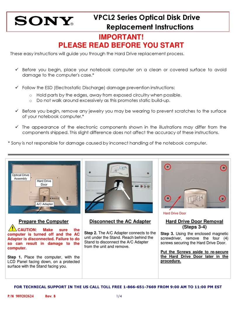
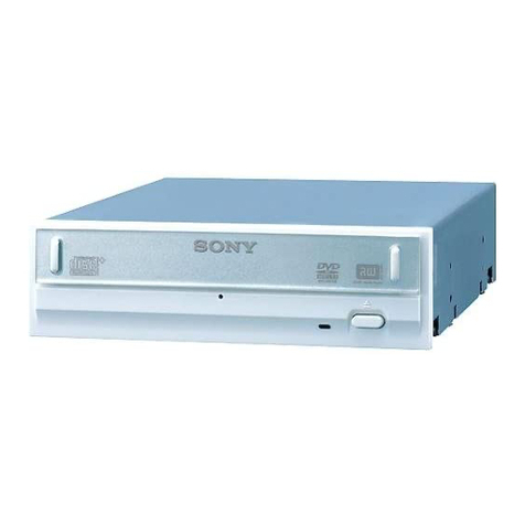
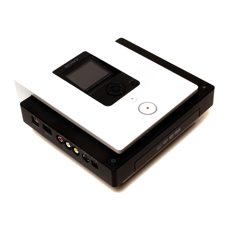
Sony PDW-U4 User manual

SERVICE MANUAL
1st Edition
PROFESSIONAL DISC DRIVE UNIT
PDW-U4
利用条件:
① 本情報はソニー製品の販売,設置,設定,使用の目的でのみご利用ください。かかる
目的以外での利用を禁止します。
② 著作者の事前の書面による許可なく,本情報の全部または一部の複写,複製,転載,
改変,翻訳,送信等を禁止します。
情報改訂:
本情報は,当社の裁量により,予告なく変更されることがあります。ご使用される場合,
本情報が最新の情報であることを確認のうえ,ご使用ください。
Conditions of Use:
(1) Please use this information only for the purpose of sales, installation, configuration,
and use of Sony products. Using this information for any purpose other than the purpose
described foregoing is forbidden.
(2) Do not copy, replicate, reproduce, alter, translate, transmit, sell, lease, or distribute this
information in whole or in part without the prior written permission of the author.
Revision of Information:
This information may be changed or updated at any time without any prior notice. Please
confirm that this information is up-to-date before using it.

警告
このマニュアルは,サービス専用です。
お客様が,このマニュアルに記載された設置や保守,点検,修理などを行うと感電や火災,
人身事故につながることがあります。
危険をさけるため,サービストレーニングを受けた技術者のみご使用ください。
WARNING
This manual is intended for qualified service personnel only.
To reduce the risk of electric shock, fire or injury, do not perform any servicing other than that
contained in the operating instructions unless you are qualified to do so. Refer all servicing to
qualified service personnel.
WARNUNG
Die Anleitung ist nur für qualifiziertes Fachpersonal bestimmt.
Alle Wartungsarbeiten dürfen nur von qualifiziertem Fachpersonal ausgeführt werden. Um die
Gefahr eines elektrischen Schlages, Feuergefahr und Verletzungen zu vermeiden, sind bei
Wartungsarbeiten strikt die Angaben in der Anleitung zu befolgen. Andere als die angegeben
Wartungsarbeiten dürfen nur von Personen ausgeführt werden, die eine spezielle Befähigung
dazu besitzen.
AVERTISSEMENT
Ce manual est destiné uniquement aux personnes compétentes en charge de l’entretien. Afin
de réduire les risques de décharge électrique, d’incendie ou de blessure n’effectuer que les
réparations indiquées dans le mode d’emploi à moins d’être qualifié pour en effectuer d’autres.
Pour toute réparation faire appel à une personne compétente uniquement.
注意
外装部品を外した状態で,電源を入れないでください。
外装部品がない状態で電源を入れると,けがや感電,レーザー光による障害の原因となります。
CAUTION
Do not turn on the power with cabinet parts removed.
Turning on the power without any of exterior parts may cause injury, electric shock, or failure due to laser light.

When installing the installation space must be secured
in consideration of the ventilation and service operation.
.Do not block the ventilation slots and vents of the fans.
.Leave a space around the unit for ventilation.
.Leave more than 15 cm of space in the front of the unit
to secure the operation area.
.Leave more than 20 cm of space in the rear of the unit
to secure the operation area.
When the unit is installed on the desk or the like, leave at
least 5 cm of space in the left and right sides, 15 cm or
more of space above the unit.
設置時には,通気やサービス性を考慮して設置スペース
を確保してください。
.ファンの排気部や通気孔をふさがない。
.通気のために,セット周辺に空間をあける。
.作業エリアを確保するため,セット後方は,15 cm 以
上の空間をあける。
.作業エリアを確保するため,セット後方は,20 cm 以
上の空間をあける。
机上などの平面に設置する場合は,左側面および右側面
に5 cm 以上,上に 15cm の空間をそれぞれ確保してくだ
さい。
Laser Diode Properties
Wavelength : 400 to 410 nm
Emission duration : Continuous
Laser output power : 280 mW
(max. of pulse peak), 150 mW
(max. of CW)
Standard : IEC 60825-1:2007 &
IEC 60825-1:2014
This model (PROFESSIONAL DISC DRIVE UNIT) is
classified as a CLASS 1 LASER PRODUCT.
Use of controls or adjustments or performance
of procedures other than those specified herein
may result in hazardous radiation exposure.
CAUTION
警告
万一,異常が起きた際に,お客様が電源をきることが
できるように,設置の際には,機器近くの固定配線内
に専用遮断装置を設けるか,機器使用中に,容易に抜
き差しできるコンセントに電源プラグを接続してくだ
さい。
WARNING
When installing the unit, incorporate a readily accessible
disconnect device in the fixed wiring, or connect the
power cord to a socket-outlet which must be provided
near the unit and easily accessible, so that the user can
turn off the power in case a fault should occur.
WARNUNG
Beim Einbau des Geräts ist daher im Festkabel
ein leicht zugänglicher Unterbrecher einzufügen,
oder das Netzka-bel muß mit einer in der Nähe
des Geräts befindlichen, leicht zugänglichen
Wandsteckdose verbunden werden, damit sich bei
einer Funktionsstörung die Stromversor-gung zum Gerät
jederzeit unterbrechen läßt.

1
Table of Contents
Section 1 Service Overview .................................................................................................. 5
1-1. Operating Environment ................................................................................................................ 5
1-2. Recommended Power Cord.......................................................................................................... 6
1-3. Supplied Accessories.................................................................................................................... 7
1-4. Cables........................................................................................................................................... 7
1-5. Location of Main Parts ................................................................................................................. 8
1-5-1. Location of Boards and Circuit Configuration....................................................................... 8
1-5-2. Location of Main Mechanical Parts....................................................................................... 9
1-6. Location of Sensors and Their Functions................................................................................... 10
1-7. To Eject Cartridge Manually ...................................................................................................... 11
1-8. Circuit-Protection Part List ........................................................................................................ 11
1-8-1. Fuse...................................................................................................................................... 11
1-9. Setting Onboard Switch ............................................................................................................. 12
1-9-1. BD-48 Board........................................................................................................................ 12
1-10. Equipment and Fixtures List for Check/Adjustment ................................................................ 13
1-10-1. Tools................................................................................................................................... 13
1-10-2. Equipment List for Checking and Adjustment................................................................... 14
1-11. XDCAM Drive Utility Software .............................................................................................. 15
1-12. Cables to Handle with Care...................................................................................................... 16
1-12-1. Disconnecting/Connecting Flexible Cable (FFC, FPC)..................................................... 16
1-12-2. Disconnecting/Connecting Fine-Wire Coaxial Cable ........................................................ 17
1-12-3. Disconnecting/Connecting Power Harness ........................................................................ 19
1-13. Cautions on Handling the Optical Block Assembly ................................................................. 20
Section 2 Periodic Inspection and Maintenance.................................................................. 22
2-1. Periodic Inspection..................................................................................................................... 22
2-1-1. Digital Hours Meter ............................................................................................................. 22
2-1-2. Periodic Inspection and Replacement Parts List .................................................................. 23
2-2. Cleaning ..................................................................................................................................... 24
2-2-1. General Information for Cleaning Using Cleaning Cloth .................................................... 24
2-2-2. Cleaning the Loader Assembly ............................................................................................ 24
2-2-3. Cleaning the Spindle Motor................................................................................................. 25
2-2-4. Cleaning after Operation in Special Environment ............................................................... 26
2-2-5. Cleaning the Pickup Lens .................................................................................................... 27
Section 3 Troubleshooting................................................................................................... 28
3-1. Overview of Error Indication ..................................................................................................... 28
3-2. Error Codes ................................................................................................................................ 29
3-2-1. Error 0X............................................................................................................................... 30

2
3-2-2. Error 20................................................................................................................................ 38
3-2-3. Error 3X............................................................................................................................... 41
3-2-4. Error 5X............................................................................................................................... 44
3-2-5. Error 6X............................................................................................................................... 47
3-2-6. Error 91................................................................................................................................ 50
3-2-7. Error 95................................................................................................................................ 55
Section 4 Replacement of Main Parts.................................................................................. 63
4-1. General Information for Parts Replacement............................................................................... 63
4-1-1. Index .................................................................................................................................... 63
4-1-2. Tightening Torque................................................................................................................ 65
4-2. Removing/Installing the Cabinet ................................................................................................ 66
4-2-1. Front Panel Assembly .......................................................................................................... 66
4-2-2. Rear Panel............................................................................................................................ 68
4-3. Loader Assembly........................................................................................................................ 69
4-4. Loading Motor Assembly........................................................................................................... 73
4-5. Optical Block Assembly............................................................................................................. 75
4-5-1. Replacement Procedure ....................................................................................................... 75
4-5-2. Action after Replacement or Repair..................................................................................... 80
4-6. BU Assembly Sled Motor........................................................................................................... 81
4-7. Spindle Motor............................................................................................................................. 83
4-8. DC Fan (52 Square) Assembly................................................................................................... 84
4-9. DC Fan (40 Square) Assembly................................................................................................... 85
4-10. Front Frame Assembly ............................................................................................................. 87
4-11. Replacement of Board .............................................................................................................. 88
4-11-1. BD-48 Board...................................................................................................................... 88
4-11-2. UI-32 Board ....................................................................................................................... 94
4-11-3. JK-109 Board..................................................................................................................... 96
4-11-4. KY-800 Board .................................................................................................................... 97
4-11-5. LDR-35 Board ................................................................................................................... 98
4-11-6. LDR-36 Board ................................................................................................................... 99
4-11-7. SE-1004A Board .............................................................................................................. 100
4-11-8. SE-1005A Board .............................................................................................................. 102
4-12. Replacing EEPROM (IC722/BD-48 Board) .......................................................................... 103
Section 5 Firmware Update ............................................................................................... 104
5-1. Checking the Firmware Version ............................................................................................... 104
5-2. Updaing the Firmware.............................................................................................................. 105
Section 6 Maintenance Menu ............................................................................................ 107
6-1. Overview .................................................................................................................................. 107
6-2. Starting the Maintenance Menu................................................................................................ 107
6-3. Maintenance Menu List............................................................................................................ 110

3
6-4. CHECK Menu .......................................................................................................................... 111
6-4-1. DEVICE, TEMPERATURE SENSOR .............................................................................. 111
6-4-2. DEVICE, FAN MOTOR.................................................................................................... 112
6-4-3. DEVICE, ACCELERATION SENSOR (STATIC)............................................................ 113
6-4-4. LOADER ........................................................................................................................... 115
6-4-5. SLIDER ............................................................................................................................. 120
6-4-6. SPINDLE MOTOR............................................................................................................ 121
6-4-7. OPTICAL BLOCK, SA ACTUATOR ............................................................................... 122
6-4-8. OPTICAL BLOCK, LASER.............................................................................................. 123
6-4-9. LENS CLEANING ............................................................................................................ 124
6-5. REPLACE Menu...................................................................................................................... 125
6-5-1. OPTICAL BLOCK ............................................................................................................ 125
6-5-2. BD BOARD....................................................................................................................... 127
6-5-3. SE BOARD........................................................................................................................ 129
6-6. ERROR LOGGER ................................................................................................................... 130
6-7. OTHERS Menu ........................................................................................................................ 132
6-7-1. VERSION .......................................................................................................................... 132
6-7-2. SERIAL NO....................................................................................................................... 132
6-7-3. MAINTENANCE HOURS, TIMERS-1............................................................................ 133
6-7-4. MAINTENANCE HOURS, TIMERS-2............................................................................ 133
6-7-5. RESET HOURS, RESET SPINDLE HOURS................................................................... 134
6-7-6. RESET HOURS, RESET LOADER COUNT ................................................................... 135
6-7-7. RESET HOURS, RESET SEEK COUNT ......................................................................... 136
Section 7 Circuit Description ............................................................................................ 137
7-1. Circuit Description ................................................................................................................... 137
7-1-1. Playback System ................................................................................................................ 137
7-1-2. Servo System ..................................................................................................................... 138
7-1-3. System Control .................................................................................................................. 139
Section 8 Spare Parts ......................................................................................................... 140
8-1. Note on Repair Parts ................................................................................................................ 140
8-2. Exploded Views........................................................................................................................ 141
Cabinet Assembly......................................................................................................................... 141
Front Assembly............................................................................................................................. 142
Frame Assembly-1........................................................................................................................ 143
Frame Assembly-2........................................................................................................................ 144
Loader Assembly.......................................................................................................................... 146
BU Assembly................................................................................................................................ 147
8-3. Supplied Accessories................................................................................................................ 148
Section 9 Diagrams............................................................................................................ 149
Overall.......................................................................................................................................... 149

5
Section 1
Service Overview
1-1. Operating Environment
Operating temperature
5 to 40 degrees-C
Operating humidity
20 to 90 % (no condensation)
Storage temperature
- 20 to 60 degrees-C
Prohibited installation places
•Places exposed to direct sunlight or intense light
•Places near a heat source
•Dusty places or places subject to constant vibration
•Places in strong magnetic field
•Places subject to much electrical noise
•Places where electrostatic noise is likely to be generated
•Places where specified installation space cannot be provided
•Sealed places
Horizontal installation condition
Allowable gradient of 30 degrees or less
Do not tilt the front or rear of the unit more than 30 degrees.
CAUTION
If the unit is used at a slant, secure it to prevent it from slipping down.
Installation direction
Installed horizontally (Disc slot is in the upper position.)
Installed vertically (EJECT button is in the lower position.)

6
1-2. Recommended Power Cord
This unit does not come with a power cord. (Except for CN model)
To get a power cord, please contact your local Sony Sales Office/Service Center.
WARN IN G
•Use the approved Power Cord (3-core mains lead)/Appliance Connector/Plug with earthing-contacts
that conforms to the safety regulations of each country if applicable.
•Use the Power Cord (3-core mains lead)/Appliance Connector/Plug conforming to the proper ratings
(Voltage, Ampere).
If you have questions on the use of the above Power Cord/Appliance Connector/Plug, please contact your
local Sony Sales Office/Service Center.
WARN IN G
Never use an injured power cord.
For customers in the U.S.A. and Canada
1: Power cord 125 V 7 A (2.0 m) 1-011-040-1x
Tip
If this type of power cord is not available, purchase a power cord 1-757-562-1x.
For customers in European countries
1: Power cord 250 V 2.5 A (2.0 m) 1-846-428-7x
Tip
If this type of power cord is not available, purchase a power cord 1-846-102-8x.
!
1
!
1

7
For customers in China
1: Power cord 250 V 2.5 A (2.0 m) 1-846-433-7x
Tip
If this type of power cord is not available, purchase a power cord 1-846-103-8x.
If the unit is used in the area except above, please contact your local Sony Sales Office/Service Center.
1-3. Supplied Accessories
•AC adaptor (1)
•USB cable (1)
•Power supply cord (1) [For CN model only]
1-4. Cables
Use the following cables or equivalent for connection to each connector.
Note
To operate this unit by the USB PD, connect it to a computer that conforms to the USB PD3.0 standard
and can supply 60 W or more power.
!
1
Panel Indication
Applicable Cable
Part Number
-
USB cable (Type C-C)
1-005-566-1x
DC IN 19.5 V
AC adaptor
1-493-482-4x
!
!

8
1-5. Location of Main Parts
1-5-1. Location of Boards and Circuit Configuration
(6)
(4)
(2)
(8)
(3)
(7)
(5)
(1)
Location No.
Board Name
Circuit Function
1
BD-48
Drive main
2
JK-109
•Power button
•DC IN
3
KY-800
Front panel
4
LDR-35
Cartridge sensor
5
LDR-36
Loading position sensor
6
SE-1004A
•EEPROM
•OP1 position sensor
•Cartridge sensor
7
SE-1005A
•OP0 position sensor
•Cartridge sensor
8
UI-32
•USB interface
•DC/DC converter

9
1-5-2. Location of Main Mechanical Parts
(1)
(7)
(4)
(5)
(6)
(2)
(2)
(8)
(9)
(3)
(6)
Location No.
Part Name
1
Loader assembly
2
Cleaner assembly
3
Loading motor assembly
4
Optical block assembly (OP-0)
5
Optical block assembly (OP-1)
6
Sled motor assembly
7
Spindle motor
8
DC fan (52 square)
9
DC fan (40 square)

10
1-6. Location of Sensors and Their Functions
(1)
(2)
(5)
(7)
(4)
(6)
(3)
Location No.
Part Name
Function
1
OP position sensor (0 side)
Detects position of the optical block assembly.
2
OP position sensor (1 side)
Detects position of the optical block assembly.
3
REC INH sensor
Detects status of the recording prohibition tab of the cartridge.
4
Cartridge DOWN sensor
Detects down position of the cartridge.
5
Cartridge IN sensor
Detects insertion of the cartridge.
6
Cartridge type sensor
Detects type of the inserted cartridge (single-layer disc to
quad-layer disc).
7
Angular speed sensor
Detects angular speed applied to the optical block.

11
1-7. To Eject Cartridge Manually
When power is not turned on, eject the cartridge from the unit according to “To eject discs with the unit
powered off” in the Operating Instructions.
1-8. Circuit-Protection Part List
1-8-1. Fuse
WARN IN G
The fuse is essential parts for safe operation. Replace the components with Sony parts whose part
numbers appear in the manual published by Sony. If the components are replaced with any parts other
than the specified ones, this may cause a fire or electric shock.
This unit is equipped with eFuse (electronic fuse).
If an overcurrent flows due to an internal fault, these fuses shut off the overcurrent to stop operation of
the unit.
In the event of operation stop, turn off the unit and inspect the inside of the unit and remove the cause of
the overcurrent.
After the current value in the unit becomes normal, the unit can be rebooted.
Board Name
Ref. No.
Address
Part Name
Part No.
Current limit set value
JK-109
IC1
Side B
TPS26631RGER
6-901-202-01
3.5 A
UI-32
IC100
Side A
TPS26631RGER
6-901-202-01
3.5 A
!
!
JK-109 Board/Side B
IC1
UI-32 Board/Side A
IC100

12
1-9. Setting Onboard Switch
1-9-1. BD-48 Board
Note
Do not turn on the switches (for factory use) while power is supplied.
Ref. No.
Name
Description
S1
System Reset
Factory use
S2
Disc Drive LSI Recovery
Factory use
S3
Disc Drive LSI Reboot
Factory use
S600
USB Reset
Factory use
S700
System Recovery
Factory use
S1
S2
S3
S600
S700
BD-48 Board/Side A

13
1-10. Equipment and Fixtures List for Check/Adjustment
1-10-1. Tools
(3)(2)(1) (4)
No.
Part No.
Name
Use
1
J-6325-110-A
Torque driver bit (M1.4/M1.7)
Tightening screws
Corresponding screws:
•P1.7 x 2.5
•Special head machine screw (M2 x2.7)
•P2 x 2
J-6325-380-A
Torque driver bit (M2.0)
Tightening screws
Corresponding screws:
•PSW2 x 5
•PSW2 x 6
•K2.6 x 8
•Shoulder screw (Φ9)
J-6323-430-A
Torque driver bit (M3.0)
Tightening screws
Corresponding screws:
•PSW3 x 20
2
J-6325-400-A
Torque driver (3 kg·cm) (0.3 N·m)
Tightening screws
J-6252-510-A
Torque driver (6 kg·cm) (0.6 N·m)
J-6252-520-A
Torque driver (12 kg·cm) (1.2 N·m)
3
3-184-527-01
Cleaning cloth (15 cm x 15 cm)
Cleaning
4
9-919-573-01
Cleaning fluid
Cleaning
–
Commercially
available
Cartridge (PFD23A, PFD50DLA, etc.)
Used in the maintenance menu.

14
1-10-2. Equipment List for Checking and Adjustment
*1: If these power cords are not available, refer to “1-2. Recommended Power Cord”.
Part No.
Name
Use
Specifications / Remarks
–
Utility software XDCAM Drive
Utility
•Firmware update, etc.
•Data read check, etc.
For obtaining the software,
contact your local Sony Sales
Office/Service Center.
–
PDW-U1 service software
Check and adjustment of drive
For obtaining the software,
contact your local Sony Sales
Office/Service Center.
–
Personal computer (PC)
For software operation
•Firmware update, etc.
•Data read check, etc.
•Check and adjustment of drive
For specifications, refer to the
Operating Instructions.
1-005-566-1x
USB cable (Type C-C)
•Firmware update, etc.
•Data read check, etc.
Supplied with the unit
1-493-482-4x
AC adaptor
DC power input of the unit
Supplied with the unit
1-011-040-1x*1
Power cord (for customers in
the U.S.A. and Canada)
DC power input of the unit
125 V 7 A (2.0 m)
1-846-428-7x*1
Power cord (for customers in
European countries)
DC power input of the unit
250 V 2.5 A (2.0 m)
1-846-433-7x*1
Power cord (for customers in
China)
DC power input of the unit
Supplied with the unit
250 V 2.5 A (2.0 m)
!
!
!
!
!

15
1-11. XDCAM Drive Utility Software
The installation method and starting method of the XDCAM Drive Utility Software (referred to as Utility
software hereafter) are described in the Operating Instructions.

16
1-12. Cables to Handle with Care
1-12-1. Disconnecting/Connecting Flexible Cable (FFC, FPC)
Note
•Be very careful not to fold flexible cables. Life of flexible cable will be significantly shortened if it is
folded.
•Each flexible cable has conductive side and insulated side. If the flexible cable is connected in the
wrong orientation of the conductive side and the insulated side, the circuit will not function.
•Check that the conductive side of the flexible cable is free from dirt or dust.
•Do not open the locking tab excessively at an angle above the value shown in the figure to prevent
the connector from being damaged.
Note
The following cables are referred to collectively as flexible cable in this manual.
•Flexible printed circuit (FPC)
•Flexible flat cable (FFC)
Locking tab
Locking tab
Connector
Insulating surface
90˚
0˚ to 20˚
Flexible cable Flexible cable
Flexible cable
90˚
Type A Angle of locking tab and
angle of connecting-disconnecting flexible cable
Angle of locking tab and
angle of connecting-disconnecting flexible cable
120˚
Locking tab
120˚
Locking tab
Connector
Flexible cable
Insulating surface
Type B
0˚
Flexible cable
Angle of connecting-disconnecting flexible cable
Connector
Type C
Flexible cable
(Upper and lower both sides
are conductive surface.)

17
Disconnecting
1. Turn off the power.
2. Slide or lift up the locking tab in the direction of the arrow to unlock and pull out the flexible cable.
Connecting
1. Slide or lift up the locking tab in the direction of the arrow and securely insert the flexible cable into
the deep end of the connector.
2. Return the locking tab to its original position and lock the connector.
1-12-2. Disconnecting/Connecting Fine-Wire Coaxial Cable
Note
•Be very careful when handling the fine-wire coaxial cable so that fine wires are not disconnected.
•When disconnecting the fine-wire coaxial cable, be sure to hold the connector. Do not attempt to pull
the cable.
•Check that the contact surface of the fine-wire coaxial cable connector is free from dirt or dust.
Connector
Connector
90˚Flexible cable
(Upper and lower both sides
are conductive surface.)
Conductive surface
Locking tab
0˚ to 20˚
Flexible cable
90˚
Type D
Locking tab
0˚
Flexible cable
Type E
Angle of locking tab and
angle of connecting-disconnecting flexible cable
Angle of locking tab and
angle of connecting-disconnecting flexible cable
Locking tab
Flexible cable
Locking tab
Other manuals for PDW-U4
1
Table of contents
Other Sony DVD Drive manuals

Sony
Sony DDU1681S Datasheet

Sony
Sony VRD-MC1 Nero 6 User manual

Sony
Sony DVDirect VRD-MC3 User manual

Sony
Sony PlayStation CFI-ZDD1 User manual

Sony
Sony DRU-820A User manual

Sony
Sony 2-586-675-11 (1) User manual

Sony
Sony VGP-DDRW4 - DVD±RW / DVD-RAM Drive User manual

Sony
Sony DRU-530A User manual

Sony
Sony DRX-820UL User manual

Sony
Sony VRD-VC30 User manual

Sony
Sony DW-Q28A User manual

Sony
Sony DDU1621 Series User manual

Sony
Sony DDU220E User manual

Sony
Sony DRU110A User manual

Sony
Sony Optiarc AD-7700S User manual

Sony
Sony DRX-510UL User manual

Sony
Sony VRD-VC20 User manual

Sony
Sony DRX-510ulk User manual

Sony
Sony DW-G120A User manual

Sony
Sony DRX-700UL User manual