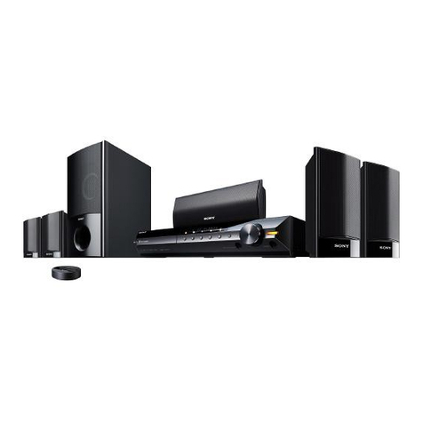
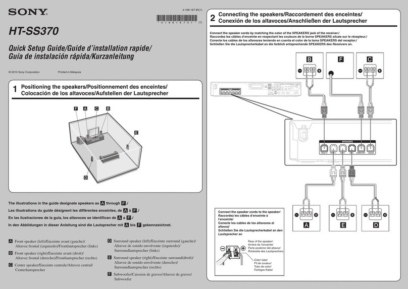
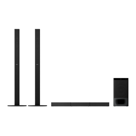
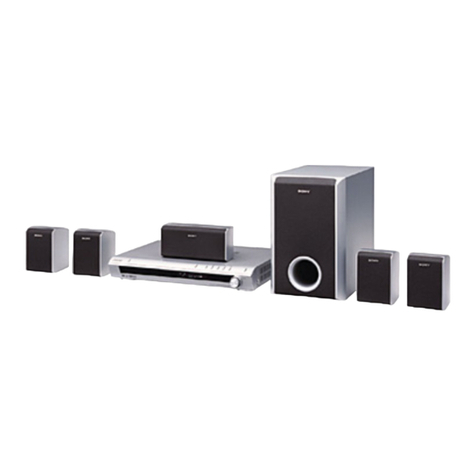
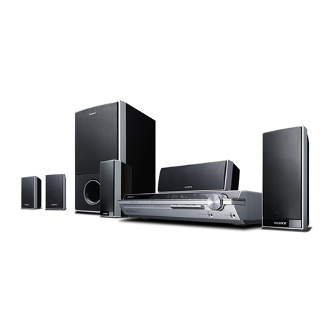
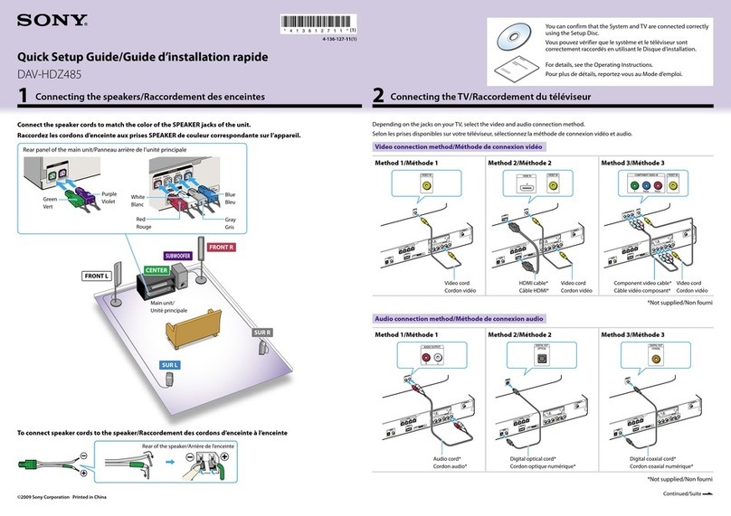
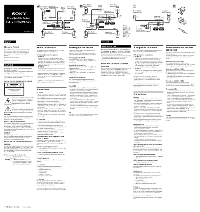
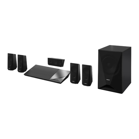
Sony SA-VE505 User manual

3-866-761-11(1)
Micro Satellite
System
Operating Instructions
Mode d'emploi
Owner's Record
The model and serial numbers are located on the rear of the unit. Record the serial
number in the space provided below. Refer to them whenever you call upon your
Sony dealer regarding this product.
Model No. SA-VE505/VE502/VE305/VE302 Serial No.
SA-VE505
SA-VE502
SA-VE305
SA-VE302
©1999 by Sony Corporation

WARNING
To prevent fire or shock hazard, do not
expose the unit to rain or moisture.
^oavoid electrical shock, do not open the cabinet.
Refer servicing to qualified personnel only.
Do not install the appliance in aconfined space,
such as abookcase or built-in cabinet.
NOTICE FOR THE CUSTOMERS IN
CANADA
CAUTION
TO PREVENT ELECTRIC SHOCK, DO NOT USE
THIS POLARIZED AC PLUG WITH AN
EXTENSION CORD, RECEPTACLE OR OTHER
OUTLET UNLESS THE BLADES CAN BE FULLY
INSERTED TO PREVENT BLADE EXPOSURE.
NOTICE FOR THE CUSTOMERS IN THE
USA
This symbol is intended to alert the
user to the presence of uninsulated
"dangerous voltage" within the
product's enclosure that may be of
sufficient magnitude to constitute a
risk of electric shock to persons.
This symbol is intended to alert the
user to the presence of important
operating and maintenance
(servicing) instructions in the
literature accompanying the
appliance.
CAUTION
You are cautioned that any changes or modification
not expressly approved in this manual could void
your authority to operate this equipment.
Note to CATV system installer:
This reminder is provided to call CATV system
installer's attention to Article 820-40 of the NEC that
provides guidelines for proper grounding and, in
particular, specifies that the cable ground shall be
connected to the grounding svstem of the building,
as close to the point of cable entry as practical.
2

Table of Contents
Hooking up the system 4
Positioning the speakers 7
Listening to the sound 8
Adjusting the sound 9
Precautions 11
Troubleshooting 12
Specifications 12
About this manual
The instructions in this manual are for SA-VE505, SA-VE502, SA-VE305, and SA-VE302,
Sony Micro Satellite Systems.
Differences between the systems
•SA-VE505 and SA-VE305
The SA-VE505 and SA-VE305 are 5.1 channel speaker systems consisting of two front speakers,
two rear speakers, one center speaker, and one subwoofer. Both support Sony Digital
Cinema Sound, Dolby* Pro Logic, and Dolby Digital (AC-3), and are thus geared
towards the enjoyment of movies.
•SA-VE502 and SA-VE302
Consisting of two front speakers and one subwoofer, the SA-VE502 and SA-VE302 are suited
for the enjoyment of music.
•Manufactured under license from Dolby Laboratories Licensing Corporation. DOLBY, the double-D symbol
,"PRO LOGIC" and "Dolby Digital (AC-3)" are trademarks of Dolby Laboratories Licensing Corporation.
Any difference in operation is clearly indicated in the text, for example, "SA-VE505 only."

Hooking up the system
Connect the speaker system to the speaker output terminals of an amplifier.
Make sure power to all components (included the subwoofer) is turned off before starting the
hook-up. 6
Hookup A(for SA-VE505/VE305)
This configuration is used when the amplifier is connected to aDVD player LD plaver VCR n
other video devices. vJ"=' ,v-lxu
Front (Right) Subwoofer
CO
!MJ
Center*
Rear (Right)
Amplifier
0© R
«ji.i.w,iliiikfl^n» Foooo
Front (Left)
eo
[Ml
eo
Rear (Left)
4

Hookup B(for SA-VE505/VE305)
Try this configuration instead of "Hookup A" in the following situations:
—When there are no jacks on the amplifier for asubwoofer.
—When you want stronger bass sound from the subwoofer.
Front (Right) Center*
e©
Amplifier —-iJ:MM
qwjo Ri»Mtfi L|
Rear (Right)
Front (Left)
Subwoofer
eo
LL
ill©
RR
Rear (Left)
*(SA-VE505 only) Connect the center speaker to the amplifier and mount it onto the supplied speaker stand for
placement on the top of the TV set (see page 7).
Terminal (jack) connections
continued

Hooking up the system (continued)
Hookup C(for SA-VE502/VE302)
This configuration is used when the amplifier is connected to aCD player MD deck
deck, or other audio devices. vl«,muara,
Front (Right)
cassette
Front (Left)
Terminal connections
Notes
'MandT *eP'U
^
(
,
+) '
1nd minUS Wte ™malS °nthe SPeakers are matched to «« corresponding the pi
(+) and the minus (-) terminals on the amplifier. <=>H"""">g me pi.
•fesure to tighten the screws of the speaker terminals securely since loose screws may become asource of
'TrlZe
J]COnneCt,°nS fi ™- C°ntart b™b<- -Peaker wires at the speaker terminals may cause
'^Z^Ti^TT^t0 1ampl,fT'sCENTER output terminal (which is for DoIbyPr°L°g- OT
uolby Digital (AC-3)). No bass will output from the subwoofer if you do
"amptfe"5r°K<1rding *eCOnneCtimS °nthe amP' ifier side-"*rto *e manual that was provided with your
Tip
minusH^Peaker Z™^ *" ^'* ™™<~> ****** "nd ^dbe to the
6

Positioning the
speakers
r
Front
(Left) W
©Li
Rear* —tfe.
(Left) &'
*SA-VE505/VE305 only
Center*
Subwoofer
W~ Front
(Right)
0t— Rear*
X> (Right)
Each speaker should face the listening
position. Better surround effect will result if
all speakers are set at the same distance from
the listening position.
Place the front speakers at asuitable distance
to the left and right of the television.
Place the subwoofer on either side of the
television.
Place the center speaker on the top-center of
the TV set.
The placement of rear speakers greatly
depends on the configuratidh of the room.
The rear speakers may be placed on both
sides of the listening position ©or behind
the listening position ©.
Tips
•Movies are best enjoyed in aroom that produces
no echoes (as in one with surrounding curtains).
•Music (especially classical music) is best enjoyed
in aroom that produces some echo.
speaker w»ut»*tw»>
SA-VE505
Attach the center speaker to supplied speaker
stand and place it on atop of the TV set.
For optimum listening enjoyment, the
speaker should face directly towards the
listener. Adjust the angle of the speaker for
mat purpose.
Bottom view _____
1Pass the speaker cord into the hole on the
back of the base and out from the hole at
the bottom of the mount.
2Secure the center speaker to the mount
with the supplied screw.
3Adjust the angle of the speaker stand.
Loosen the two screws under the base to
adjust the angle, then tighten them again
afterwards.
SA-VE305
Attach the supplied foot pads to the bottom
of the center speaker, one in each of the four
corners. Set the speaker firmly on top of the
TV set, then make sure it is completely level.
Foot pads
continued

Positioning the speakers
(continued)
Setting up other
speakers
For greater flexibility in the positioning of the
speakers, use the optional WS-FV10,
WS-TV10, or WS-WV10 speaker stand
(available only in certain countries).
WS-FV10 WS-TV10 WS-WV10
(for rear
speakers)
SA-VE305/VE302 only
You can hang or install the front (and rear)
speakers on awall using hooks or nuts
(commercially av ailable).
Note
You are responsible for the proper selection and use
of mounting hardware that you purchase at a
hardware store, and for the proper and safe
mounting of the speakers.
Tip (for SA-VE505/VE305)
IUI
The height of the front speakers should be adjusted
to about the center of the TV screen.
Listening to the sound
SA-VE505/VE502 SA-VE305/VE302
©indicator (7) ©indicator ©
First, turn down the volume on the amplifier.
The volume should be set to minimum before
you begin playing the program source.
1Turn on the amplifier and select the
program source.
2Press ®on the subwoofer.
The ©indicator on the subwoofer lights
up green.
3Play the program source.
Power turns on and off
automatically —Auto power onfoff function
(SA-VE505/VE502 only)
When the subwoofer is on (i.e, the
®indicator lights up green) and there is no
signal input for afew minutes, the
®indicator changes to red and the
subwoofer enters power saving mode. While
in this mode asignal is input to the
subwoofer, the subwoofer automatically
turns on (auto power on/off function).
To turn this feature off, slide the POWER
SAVE switch on the rear panel to OFF.
POWER
SAVE
AUTO
OFF
Note
If you turn down the volume level of the subwoofer
too low, the auto power on/off function may
activate, causing the subwoofer to enter power
saving mode.
8

I
Adjusting the sound
Slight adjustments to the system can enhance
your sound enjoyment.
pubwoofer "r,^m,.
SA-VE505/VE502
SA-VE305/VE302
LEVEL MODE
1Set MODE according to the program
source as follows:
Source MODE
DVD, LD, video cassette MOVIE
or other video source
MD, CD, cassette tape MUSIC
or other audio source
Rotate LEVEL to adjust the volume.
Set the volume level to suit the program
source.
Notes
•Some amplifier functions for enhancing the sound
may cause distortion in the subwoofer. If such
distortion occurs, turn off those functions.
•To enjoy high-quality sound, do not turn the
subwoofer volume too high.
•To increase the bass sound from the subwoofer,
connect the system using "Hookup B" (see
page 5).
LEVEL CUT OFF FREQ PHASE
1Rotate CUT OFF FREQ to set a
cut-off frequency of 100 Hz to
.150 Hz (or between 1o'clock and
3o'clock position, in terms of
position).
For Dolby Digital (AC-3), set the cut-off
frequency to the maximum level
(200 Hz).
2Rotate LEVEL to adjust the volume.
Set the volume level to suit the program
source.
3Press PHASE to select the phase
polarity (NORMAL or REVERSE).
Set PHASE to NORMAL when Dolby
Digital (AC-3) is on.
Tip
The proper phase polarity depends on the location
of asubwoofer or adjustment of the cut-off
frequency.
Try both settings and select the one that suits your
listening taste.
Notes
•Some amplifier functions for enhancing the sound
may cause distortion in the subwoofer. If such
distortion occurs, turn off those functions.
•To enjoy high-quality sound, do not turn the
subwoofer volume too high.
•To increase the bass sound from the subwoofer,
connect the system using "Hookup B" (see
page 5).
continued _
9

Adjusting the sound (continued)
Setting your amplifier
to enjoy movies
(SA-VE505/VE305 only)
For the Dolby Digital (AC-3)
If your amplifier is connected internally or
externally with aDolby Digital (AC-3)
processor, you should use the some setup
menus in the amplifier to specify the
parameters of your speaker system.
See the table below for the proper settings.
For details on the setting procedure, refer to
the manual that was provided with your
amplifier.
When "Hookup A" is used
(Speaker setup)
For Set to
Front speakers SMALL
Center speaker SMALL
Rear speakers SMALL
Subwoofer ON (or YES)
(Other setup)
Menu Set to
LFE MIX* -10 dB
BASS BOOST" ON
*Low Frequency Effect
"A function that reinforces the bass sound
When "Hookup B" is used
(Speaker setup)
For Set to
Front speakers LARGE
Center speaker SMALL
Rear speakers SMALL
Subwoofer OFF (or NO)
(Other setup)
Menu Set to
LFE MIX -10 dB
BASS BOOST ON
10
For the Dolby Pro Logic
If your amplifier is connected internally <
externally with aDolby Pro Logic proces'
you should set the surround effect mode
"NORMAL" in the amplifier for your
particular speaker system.
For details on the setting procedure, refer
the manual that was provided with your
amplifier.

Precautions
On safety
•Before operating the system, be sure that the
operating voltage of the system is identical with
that of your local power supply.
•The unit is not disconnected from the AC power
source (mains) as long as it is connected to the
wall outlet, even if the unit itself has been turned
off.
•Unplug the system from the wall outlet if it is not
to be used for an extended period of time. To
disconnect the cord, pull the cord by grasping the
plug. Never pull the cord itself.
•Should any liquid or solid object fall into the
system, unplug the system's power cord and have
the system checked by qualified personnel before
operating it any further.
•AC power cord must be changed only at the
qualified service shop.
On operation
•Do not drive the speaker system with a
continuous wattage exceeding the maximum
input power of the system.
•If the polarity of the speaker connections are not
correct, the bass tones will be weak and the
position of the various instruments obscure.
•Contact between bear speaker wires at the speaker
terminals may result in ashort-circuit.
•Before connecting, turn off the amplifier to avoid
damaging the speaker system.
•The speaker grille cannot be removed. Do not
attempt to remove the grille on the speaker
system. If you try to remove it, you may damage
the speaker.
If you encounter color irregularity on a
near by TV screen
This speaker system is magnetically shielded to
allow it to be installed near aTV set. However,
color irregularities may still be observed on certain
types of TV sets.
If color irregularity is observed...
»Turn off the TV set once, then turn it on again
after 15 to 30 minutes.
If color irregularity is observed again...
*Place the speakers further away from the TV
set.
If howling occurs
Reposition the speakers or turn down the volume
on the amplifier.
On placement
•Do not place the speakers in an inclined position.
•Do not place the speakers in locations that are:
—Extremely hot or cold
—Dusty or dirty
—Very humid
—Subject to vibrations
—Subject to direct sunlight
On cleaning
Clean the speaker cabinets with a soft cloth lightly
moistened with amild detergent solution or water.
Do not use any type of abrasive pad, scouring
powder or solvent such as alcohol or benzine.
If you have any questions or problems concerning
your speaker system, please consult your nearest
Sony dealer.
11

I
Troubleshooting
Should you encounter aproblem with your
Uketh rS>em'C
i
heCk thC f0l '°WinS,is^d
take the inchoated measures. If the problem
persist, consult your nearest Sony dealer.
Specifications
There Is no sound from the speaker^ ~~"
system.
•Make sure all the connections have been
correctly made.
•Make sure the volume on the amplifier
has been turned up properly.
•Make sure the program source selector on
the ampl,f,er ,s set to the proper source
•Check if headphones are connected If
^Jneyare^disconnect them.
output* diSt°^°ni^^^
•Make sure the cut-off frequency on the
onnT>!er ,
Set t0 the ma™™level
(SA%
HElo^°lbyDieifaI(AC"3)iSOn
•Check if any sound-enhancing functions
have been activated on the amplifier If
they have, turn them off.
There is hum or noise in the speaker
output.
•Make sure all the connections have been
correctly made.
•Make sure none of the audio components
^^repositioned too close to the TV set.
The sound has suddenlyltopp^d!
•Make sure all the connections have been
correctly made. Contact between bear
speaker wires at the speaker terminals
^maycause ashort-circuit.
SA-VE505/VE502
For the U.S. model
AUDIO POWER SPECIFICATION-
POWER OUTPUT AND TOTAL
HARMONIC DISTORTION:
with 8ohm loads both channels driven,
20 -150 Hz; rated 100 watts per channel
m,mmum RMS power, with no more th,
08 /0 total harmonic distortion from
250 milliwatts to rated output.
SS-MS5 (front, center, and rear
speakers)
Speaker system
Speaker units
Enclosure type
Rated impedance
Power handling capacity
Maximum input power:
Sensitivity level
Frequency range
Dimensions (w/h/d)
Mass
Full range x2,
magnetically shieldc
5cm (2 in.), balance ,
type
Bass reflex
8ohms
120 watts
87dB(l W, lm)
120 Hz -20,000 Hz
Approx. 77x131 x
105 mm (3 1/8x51/4
4'/4 in.), including fr,
grille
Approx. 131 x125 x
113mm(5'/4X5x
4'/2 in.), with center
speaker stand attatche.
Approx. 730 g(l lb 10
each
12
SA-WMS5 (subwoofer)
System
Speaker system Active subwoofer
Vaker unit
„.cone type
Enclosure type Advanced SAW type
Practical maximum output yP
n100 W
Keproduction frequency range
Inputs 26 Hz -150 Hz
LINE IN (input pin jack)
SPEAKER IN (input terminals)
Outputs
LINE OUT (output pin jack)
SHAKER OUT (output terminals)
Power requirements
USA and Canada: 120 VAC, 60 Hz
220 -230 VAC, 50/60 Hy
Power consumptions VAQ 50/60 H>

Dimensions (w/h/d) Approx. 230 x380 x
440 mm(9'/sxl5x
17 3/8 in.), including front
Mass Approx. 13 kg
(28 lb 10 oz)
Supplied accessories
SA-VESOS
Center speaker stand (1)
Screw (for the center speaker) (1)
Audio connecting cord (1)
Speaker connecting cords, 10 m
(32 ft 9V. in.) (2)
Speaker connecting cords, 2.5 m
(8 ft 27, in.) (5)
SA-VES02
Audio connecting cord (1)
Speaker connecting cords 25m
(8 ft 27; in.) (4)
Design and specifications are subject to change
without notice.
SA-VE305/VE302
For the U.S. model
AUDIO POWER SPECIFICATIONS
POWER OUTPUT AND TOTAL
HARMONIC DISTORTION:
with 6ohm loads both channels driven, from
20 -150 Hz; rated 100 watts per channel
minimum RMS power, with no more than
0.8% total harmonic distortion from
250 milliwatts to rated output.
SS-V305 {front and rear speakers)
Speaker system
Speaker units
Full range, magnetically
shielded
5x9cm (2 x3Vs in.),
cone-type
Enclosure type Bass reflex
Rated impedance 8ohms
Power handling capacity
Maximum input power: 100 watts
Sensitivity level 86 dB (1 W, 1m)
Frequency range 90 Hz -20,000 Hz
Dimensions (w/h/d) Approx. 68 x151 x
135 mm (2 3/4 x6x
53/8 in.), including front
.. grille
Mass Approx. 790 g(1 lb 12 oz)
each
SS-CN305 (center speaker)
Speaker system Full range x2,
„,magnetically shielded
Speaker units 5x9cm (2 x3V« in.),
cone type
Enclosure type Bass reflex
Rated impedance 8ohms
Power handling capacity
Maximum input power: 120 watts
Sensitivity level 88 dB (1 W1m)
Frequency range 90 Hz -20,000 Hz
D,mensions (w/h/d) Approx. 301 x68 x
137 mm (11 7sx2V4x
5'/2 in.), including front
M„ grilIe
Approx. 1.5 kg (3 lb 5oz)
SA-W30SG (subwoofer)
System
Speaker system Active subwoofer,
<;„„.,, .Lmagnetically shielded
Speaker unit Woofer: !6 cm (6 3/8in.,,
ccone type
Enclosure type Advanced SAW type
1rachcal maximum output
USA: 60 w
Others: 50 w
Reproduction frequency range
„. .,28 Hz -200 Hz
High frequency cut-off frequency
50 Hz -200 Hz
Phase selector NORMAL, REVERSE
Inputs
LINE IN (input pin jack)
SPEAKER IN (input terminals)
Outputs
LINE OUT (output pin jack)
SPEAKER OUT (output terminals)
General
Power requirements
USA and Canada: 120 VAC, 60 Hz
fur°Pe: 220 -230 VAC, 50/60 Hz
Singapore and Malaysia: 110 -220/220 -240 VAC
50/60 Hz
°thers: 220 -240 VAC, 50/60 Hz
Power consumptions
USA: 35 W
Others: 45
Dimensions (w/h/d) Approx. 205 x380 x
395 mm (8 78 x15 x
15 5/8in.), including front
grille
Mass Approx. 9.5 kg
(20 lbl5oz)
Supplied accessories
SA-VE305
Foot pads (4)
Audio connecting cord (1)
Speaker connecting cords 10 m
(32 ft 97. in.) (2)
Speaker connecting cords, 2.5 m
(8 ft 27; in.) (5)
SA-VE302
Audio connecting cord (1)
Speaker connecting cords, 2.5 m
(8 ft 27: in.) (4)
Design and specifications are subject to change
without notice.
13

AVERTISSEMENT
Pour eviter tout risque de feu ou de choc
electrique, ne pas exposer cet appareil ala
pluie ou aI'humidite.
Pour eviter tout choc electrique, ne pas ouvrir le
coffret. Confier I'entretien ii un personnel qualifie.
N'installez pas I'appareil dans un espace confine
comme dans une bibliotheque ou un meuble
encastre.
NOTICE POUR LES CLIENTS AU CANADA
ATTENTION
POUR PREVEN1R LES CHOCS ELECTR1QUES, NE
PAS UTIL1SER CETTE FICHE POLARISEE AVEC
UN PROLONGATEUR, UNE PRISE DE COURANT
OU UNE AUTRE SORTIE DE COURANT, SAUF SI
LES LAMES PEUVENT ETRE INSEREES AFOND
SANS EN LAISSER AUCUNE PARTIE A
DECOUVERT.
2

Table des matieres
Raccordement du systeme
acoustique 4
Emplacement des enceintes 7
Ecoute du son 8
Reglage du son 9
Precautions 11
Guide de depannage 12
Specifications 12
Apropos de ce manuel
^-VE^SA-V
e
EMTnUel C°nCement l8S SyStemeS Mkro Satel,ite SonrSA-VE505, SA-VE502,
Differences entre les systemes
•SA-VE505 et SA-VE305
Les SA-VE505 et SA-VE305 sont des systemes acoustiques a5.1 canaux, comprenant deux
enceintes avant, deux enceintes arriere, une enceinte centrale et un caisson de grave Ces deux
DSrS
Ar P
,r?enV!Sf°n,
Cti0nS Digita'Cinema S°Und de Sony- Dolby* Pro Logic et Dolby
Digital (AC-3) et sont done destines ala reproduction du son cinematoeraphique
•SA-VE502 et SA-VE302
Les SA-VE502 et SA-VE302 component deux enceintes avant et un caisson de grave
done destines a1ecoute de la musique.
*Fabrique sous licence de Dolby Laboratories Licensing Corporation
Sn^' 'eSymb0led0li
bIe-Dm<PR0LOGIC et Dolby Digital (AC-3) sont des marques de Dolby
Laboratories Licensing Corporation.
T
£TZrl!?Je"Cfde fonctionn«nent est clairement indiquec dans le texte, par exempli-,
bA-VE505 seulement .r
Is sont

Raccordement du systeme acoustique
Raccordez le systeme acoustique aux bornes d'enceintes de l'amplificateur.
Avant de raccorder les cordons, assurez-vous que tous les appareils (caisson de grave compris
sont hors tension.
Raccordement A(SA-VE505/VE305)
Cette configuration doit etre utilisee lorsque l'amplificateur est raccord6 aun lecteur DVD, un
lecteur LD, un magnetoscope ou aun autre appareil video.
Avant (droite)
Caisson de grave Centre* Avant (gauche
Arriere (droite) Arriere (gauche
4

Raccordement B(SA-VE505/VE305)
Essayez cette configuration au lieu du "Raccordement A" dans les situations suivantes:
—l'amplificateur n'a pas de prises pour le raccordement d'un caisson de grave.
—vous voulez que le caisson de grave produise un son grave plus puissant.
Avant (droite) Centre* Avant (gauche)
Arriere (droite) Arriere (gauche)
*(SA-VE505 seulement) Raccordez i'enceinte centrale ai'amplificateur et mettez-la sur le pied d'enceinte foumi
pour l'installer sur un televiseur (voir page 7).
Connexion aux bornes (jacks)
suite

Raccordement du systeme acoustique (suite)
Raccordement C(SA-VE502/VE302)
Cette configuration doit etre utilisee lorsque l'amplificateur est raccorde aun lecteur CD, une
platine MD, une platine acassette ou un autre appareil audio.
Avant (droite) Avant (gauchf
Connexion aux homes
Remarques
•Assurez-vous que les bornes plus (+) et moins (-) des enceintes correspondent aux bornes plus (+) et (-) d
l'amplificateur.
•Veillez abien serrer les vis des bomes d'enceintes, car des vis desserrees peuvent etre une source de bruit
•Veillez ainserer afond les fils dans les bornes. Le contact de fils d'enceintes nus au niveau des bornes pei
causer un court-circuit.
•Ne raccordez pas le caisson de grave ala borne de sortie CENTER de l'amplificateur (qui est reserve au D
Pro Logic ou au Dolby Digital (AC-3)). Aucun son ne sera sinon fourni par le caisson de grave.
•Pour les connexions cote amplificateur, reportez-vous au manuel fourni avec l'amplificateur.
Conseil
Tous les fils rayes sont de polarite negative (-) et doivent etre raccordes aux bornes d'enceintes moins (-).
6

Emplacement des
enceintes
Position de chaque
enceinte
Centre*
Caisson de grave
Avant <^@5~ Avant
(gauche)
0\$
Arriere* —
(gauche) Q
(droite)
Bo
.^fjr~ Arriere*
^(droite)
•SA-VE505A/E305 seulement
Chaque enceinte doit etre dirigee vers la
position d'ecoute. L'effet surround sera bien
meilleur si toutes les enceintes sont aegale
distance de la position d'ecoute.
Installez les enceintes avant aune distance
correcte adroite et agauche du televiseur.
Installez le caisson de grave adroite ou a
gauche du televiseur.
Installez l'enceinte centrale sur le televiseur.
L'emplacement des enceintes arriere depend
en grande partie de la grandeur de la piece.
Les enceintes arriere peuvent etre installees
sur les deux cotes de la position d'ecoute ©
ou derriere la position d'ecoute 0.
Conseils
•II est preferable de regarder les films dans une
piece sans echo (avec rideaux par exemple).
•II est preferable d'ecouter la musique (surtout la
musique classique) dans une piece avec un leger
echo.
Installation de
l'enceinte centrale
SA-VE505
Fixez l'enceinte centrale au pied d'enceinte
fourni pour l'installer sur un televiseur.
Dirigez l'enceinte vers le visage de l'auditeur
pour obtenir un son de haute qualite. Pour ce
faire, orientez le pied d'enceinte vers le haut
ou ie bas.
*15°
,25°
Dessous
1Faites passer le cordon d'enceinte dans
l'orifice al'arriere de la base et ressortir par
l'orifice sous la monture.
2Fixez l'enceinte centrale ala monture avec
la vis fournie.
3Reorientez le pied d'enceinte.
Desserrez les deux vis sous la base avant
d'ajuster Tangle et resserrez-les apres
l'avoir ajuste.
SA-VE305
Collez les tampons fournis sous l'enceinte
centrale, un dans chacun des quatre coins.
Installez correctement l'enceinte sur le
televiseur et assurez-vous qu'elle est de
niveau.
Tampons
autocollants
suite

Emplacement des enceintes (suite)
Installation des autres ,
enceintes v......w;»**'^
Les pieds d'enceintes WS-FV10, WS-TV10 ou
WS-WV10 (disponibles en option dans
certains pays), offrent une plus grande
flexibility lors de Installation des enceintes.
WS-FV10 WS-TV10 WS-WV10
(pour
enceintes
arriere)
SA-VE305/VE302 settlement
Les enceintes avant (et arriere) peuvent etre
suspendues ou installees sur mur al'aide de
crochets ou ecrous (en vente dans le
commerce).
60 mm
Ecrous (M5)
Remarque
Vous etes responsable de la selection et de l'emploi
corrects du materiel de montage que vous vous
procurez chez un quincaillier et du montage
approprie et sur des enceintes.
Conseil (for SA-VE505A/E305)
0
Les enceintes avant doivent etre a la hauteur du
centre du televiseur.
Ecoute du son
SA-VE505/VE502 SA-VE305/VE302
Voyant ®Voyant ®
Reduisez d'abord le volume sur
l'amplificateur. Le volume doit etre redu
maximum avant l'ecoute de la source.
1Allumez l'amplificateur et
selectionnez la source.
2Appuyez sur ®du caisson de
grave.
Le temoin ©sur le caisson de grave
s'allume en vert.
3Reproduisez la source.
Le caisson de grave s'allume et
s'eteint automatiquement
(SA-VE505/VE502 seulement)
Si le caisson de grave est en service (c'est-
dire le voyant ®est allume en vert) mais
qu'aucun signal n'est fourni pendant
quelques minutes, le voyant ©deviendra
rouge et le caisson de grave se mettra en
mode d'economie d'energie. Lorsqu'un si
est transmis au caisson de grave dans ce
mode, le caisson s'allume automatiquenu
(fonction de marche/arret automatiques).
Pour mettre cette fonction hors service, re
le commutateur POWER SAVE sur le
panneau arriere sur OFF.
POWER
SAVE
r5a
Remarque
Si vous reduisez trop le volume du caisson de g
la fonction de marche/arret automatiques peut
entrer en service et mettre le caisson en mode
d'economie d'energie.
This manual suits for next models
3
Table of contents
Languages:
Other Sony Home Theater System manuals

Sony
Sony HT-K5 User manual

Sony
Sony BDV-T79 User manual

Sony
Sony HTSS1000P. User manual

Sony
Sony DAV-FX10 - Dvd Dream System User manual

Sony
Sony SA-VE335 User manual

Sony
Sony HT-CT60 User manual

Sony
Sony DAV-DX155 Quick start guide

Sony
Sony HT-RT5 User manual

Sony
Sony HS-703 User manual

Sony
Sony DAV-LF1H User manual

Sony
Sony DAV-FX10 - Dvd Dream System User manual

Sony
Sony HT-DDW740 Instruction manual

Sony
Sony BRAVIA DAV-DZ170 User manual

Sony
Sony BDV-NF720 User manual

Sony
Sony HT-XT100 User guide

Sony
Sony HT-RD150 User manual

Sony
Sony SRX-R515P User manual

Sony
Sony LKRA-009 User manual

Sony
Sony HT-DDW880 Instruction manual

Sony
Sony SA-SS888 User manual