Sony Vaio VPCP1 Series User manual

Sony Confidential
PERSONAL COMPUTER
V
PCP1 Series
SERVICE MANUAL
Revision History
Design and specifications are subject to change without
notice.
9-890-803-03
Ver.3-2010H
Area Model Lineup
Japanese Japanese
American
US
Canadian
Latin
Area Model Lineup
American Latin
European AEP/UK
Asian/Oceania/
South Africa
International
Korean
Taiwan
Chinese
ʳCTO Model
VPCP115KG/B
VPCP115KG/D
VPCP115KG/P
VPCP115KG/W
VPCP116KG/B
VPCP115KW/B
VPCP115KW/D
VPCP115KW/P
VP
C
P11
5
KW
/
W
VPCP119KJ/D
VPCP119KJ/P
VPCP119KJ/W
VPCP11AKJ
VPCP11ALJ
VPCP11AVJ
VPCP111KX/B
VPCP111KX/D
VPCP111KX/G
VPCP111KX/P
VPCP111KX/W
VPCP112KX/B
VPCP112KX/D
VPCP112KX/G
VPCP112KX/P
VPCP112KX/W
VPCP113KX/B
VPCP113KX/D
VPCP113KX/G
VPCP113KX/P
VPCP113KX/W
VPCP114KX/B
VPCP114KX/D
VPCP114KX/G
VPCP114KX/P
VPCP114KX/W
VPCP116KX/B
VPCP116KX/D
VPCP116KX/G
VPCP116KX/P
VPCP116KX/W
VPCP118KX/B
VPCP118KX/D
VPCP118KX/G
VPCP118KX/P
VPCP118KX/W
VPCP11SKX/BI
VPCP11SKX/PI
VPCP110JB/B
VPCP110JB/BI
VPCP110JB/D
VPCP110JB/G
VPCP110JB/PI
VPCP110JB/W
VPCP110KL/B
VPCP110KL/BI
VPCP11S1E/B
VPCP11S1E/D
VPCP11S1E/G
VPCP11S1E/P
VPCP11S1E/W
VPCP11S1R/B
VPCP11S1R/D
VPCP11S1R/G
VPCP11S1R/P
VPCP11S1R/W
VPCP11Z9E/B
VPCP11Z9R/B
VPCP115JC/B
VPCP115JC/D
VPCP115JC/G
VPCP115JC/P
VPCP115JC/W
VPCP118JC/B
VPCP118JC/P
VPCP118JC/W
VPCP119JC/BI
VPCP119JC/PI
VPCP119JC/WI
VPCP115KK/B
VPCP115KK/D
VPCP115KK/P
VPCP115KK/W
VPCP110KL/D
VPCP110KL/G
VPCP110KL/P
VPCP110KL/WI

Information in this document is subject to
change without notice.
Sony, VAIO and CLIE are trademarks or regis-
tered trademarks of Sony. Microsoft, Windows,
Windows Media, Outlook, Bookshelf and other
Microsoft products are trademarks or registered
trademarks of Microsoft Corporation in the
United States and other countries. The word
Bluetooth and the Bluetooth logo are trademarks
of Bluetooth SIG, Inc.AMD, the AMD logo, other
AMD product names and combinations thereof
are trademarks of Advanced Micro Devices, Inc.
IntelInside logo, Pentium, Celeron and Core are
trademarks or registered trademarks of IntelCor-
poration. Transmeta, the Transmeta logo, Crusoe
Processor, the Crusoe logo and combinations
thereof are trademarks of Transmeta Corporation
in the USA and other countries. Graffiti, Hot-
Sync, PalmModem, and Palm OSare registered
trademarks, and the Hotsync logo and Palm are
trademarks of Palm, Inc. or its subsidiaries. (M)
and Motrola are trademarks of Motrora, Inc. Other
Motrola products and services with (R) mark like
Dragomball are the trademarks of Motrola, Inc.
All other names of systems, products and services
in this manualare trademarks or registered trade-
marks of their respective owners. In this manual,
the (TM) or (R) mark are not specified.
Caution Markings for Lithium/Ion Battery- The
following or similar texts shall be provided on
batterypack of equipment or in both the operating
and the service instructions.
CAUTION: Danger of explosion if batteryis
incorrectly replaced. Replace only with the same
or equivalent type recommended bythe manu-
facturer. Discard used batteries according to the
manufacturer’s instructions.
CAUTION: The batterypack used in this device
maypresent a fire or chemicalburn hazard if mis-
treated. Do not disassemble, heat above 60°C
(140°F) or incinerate. Dispose of used battery
promptly. Keep awayfrom children.
CAUTION: Changing the back up battery.
•Overcharging, short circuiting, reverse charg-
ing, multilation or incineration of the cells must
be avoided to prevent one or more of the fol-
lowing occurrences; release of toxic materials,
release of hydrogen and/or oxygen gas, rise in
surface temperature.
•If a cell has leaked or vented, it should be
replaced immediately while avoiding to touch
it without anyprotection.
Serviceand Inspection Precautions
1. Obey precautionary markings and
instructions
Labels and stamps on the cabinet, chassis, and
components identifyareas requiring specialpre-
cautions. Be sure to observe these precautions,
as well as all precautions listed in the operating
manualand other associated documents.
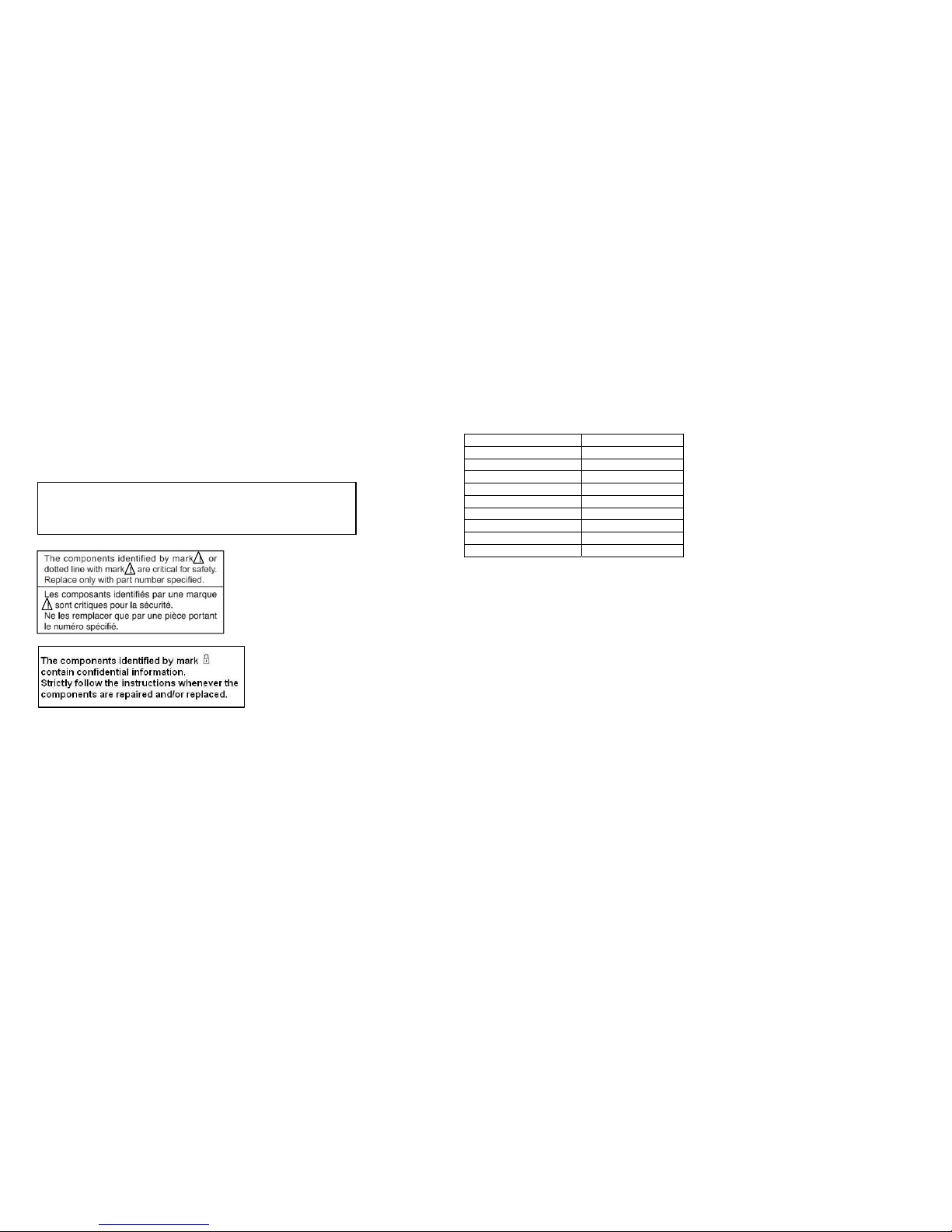
2. Use designated parts only
The set’s components possess important safety
characteristics, such as noncombustibilityand
the abilityto tolerate large voltages. Be sure that
replacement parts possess the same safetycharac-
teristics as the originals. Also remember that the
mark, which appears in circuit diagrams and
parts lists, denotes components that have particu-
larly important safetyfunctions; be extra sure to
use only the designated components.
3. Always follow the original design
when mounting parts and routing
wires
The originallayout includes various safetyfea-
tures, such as inclusion of insulating materials
(tubes and tape) and the mounting of parts above
the printer board. In addition, internalwiring has
been routed and clamped so as to keep it away
from hot or high-voltage parts. When mounting
parts or routing wires, therefore, be sure to du-
plicate the originallayout.
4. Inspectafter completing service
After servicing, inspect to make sure that all
screws, components, and wiring have been
returned to their originalcondition. Also check
the area around the repair location to ensure that
repair work has caused no damage, and confirm
safety.
5. When replacing chip components...
Never reuse components. Also remember that
the negative side of tantalum capacitors is easily
damaged byheat.
6. When handling flexible print
boards...
•The temperature of the soldering-iron tip
should be about 270°C.
•Do not apply the tip more than three times to
the same pattern.
•Handle patterns with care; never apply force.
Caution: Remember that hard disk drives are
easily damaged byvibration. Always handle
with care.
2[Sony Confidential]
VPCP1 Series (9-890-803-XX)
7KHFRPSRQHQWVLGHQWLILHGE\PDUN FRQWDLQ
FRQ¿GHQWLDOLQIRUPDWLRQ
6WULFWO\IROORZWKHLQVWUXFWLRQVZKHQHYHUWKH
FRPSRQHQWVDUHUHSDLUHGDQGRUUHSODFHG

TABLE OF CONTENTS
Section Title Page
CHAPTER1. BLOCK DIAGRAM
1-1.VPCP1 Series…………………………………………..
(to1-1)
CHAPTER2. FRAME HARNESS DIAGRAM
2-1. VPCP1 Series (TOP)……………………………………
2-2. VPCP1 Series (BOTTOM)……………………………..
(to2-2)
CHAPTER3. EXPLODED VIEWS AND PARTS LIST
Note…………………………………………………………….
Screws
S-1.Screws………………………………………………
Palmrest
P-1.Palmrest………….…………………………………
Main Board
M-1.Main Board……….…………………………………
Bottom
B-1.Bottom………….…………………………………..
HDD (SSD)
H-1.HDD (SSD)…………………………………………
LCD
L-1.LCD……………………………………………….…
ACCESSORIES
A-1.ACCESSORIES……………………………………
(to3-9)
CHAPTER4.OTHERS
4-1. Note for WWAN Board Replacement……………………
(to 4-1)
1-1
2-1
2-2
3-3
3-4
3-5
3-6
xSPECIFICATIONS are listed on page 3-1 of
“CHAPTER3. EXPLODED VIEWS AND PARTS LIST”.
xHistory of the changes is shown as the “Revision
History” at the end of this data.
[Sony Confidential]
3
3-2
3-9
VPCP1 Series (9-890-803-XX)
3-7
3-8
4-1

CHAPTER1.
BLOCK DIAGRAM
1-1.VPCP1 Series
1-1
(END)
Silverthorne
CPU
FCBGA8 441
Poulsbo
SCH
FCBGA1249
DC jack
IMVP6
VR
Chrontel
CH7317B
LCD 8.0’’
1600 x 768
Multimedia SIM
XDP
SDVO
USB
PATA
FSB
GbE
Marvell
88E8059
WAN/1seg
BT
Memory Card
EEPROM (SPD)
256Byte
Illumination
Senso
r
[Sony Confidential]
VPCP1 Series (9
-
890
-
803
-
XX)
WLAN/WIMAX
USB 1
LVDS
USB 2
Camera
MS
SD
0
1
2
3
4
5
6
7
RGB
Dongle
Magnetic
Module RJ-45
PCI Express
0
SATA SSD
(With
PATA-SATA
conversion
Bridge)
or
PATA SSD
DDR2 533MHZ
On-board
Memory
Potentiometer EEPROM (NCHP)
Audio Codec
RealTek
ALC275
SMBus
NC Headphone Jack
Internal Speaker
Internal MIC
KBC
H8S/2112R
DEBUG
Touchpad
Stick Pointer
Keyboard
Switch LED
SPL Flash
16Mbit
Thermal
Sensors
Acceleration sensors
Geomagnetism sensor
PS/2
PS/2
SMBus
LPC
Azalia
I C
2

CHAPTER2.
FRAMEHARNESSDIAGRAM
2-1. VPCP1 Series (TOP)
TOUCHPAD
CAMERA
White
Gray
MDL-45 ANTENNA
WWAN ANTENNA
MDL-45
WLAN
ANTENNA
SWX-346
AUDIO BOARD
MOTHERBOARD
WWAN BOARD
DC-IN
USB
HEADPHONE
SPEAKER
DONGLE
USB
SIM DUMMY
WWAN CARD
BATTERY FPC
LCD
CAMERA
CABLE
TOUCHPAD
CABLE
From board to connector (direct connection)
Harness (with connectors on both ends)
Harness (soldering on either end)
BLUETOOTH
MODULE
WLAN CARD
[Sony Confidential]
VPCP1 Series (9-890-803-XX)
2-1

2-2. VPCP1 Series (BOTTOM)
2-2
(END)
[Sony Confidential]
VPCP1 Series (9-890-803-XX)

CHAPTER3.
EXPLODED VIEWS AND PARTS LIST
.The parts list is compiled by blocks of a Palmrest and bottom etc.
The sections of the parts list are different depending on the model.
Please refer to list of contents shown.
Section Page
Note……………………………………………………..….……..
Screws
S-1.Screws…………………………………………….………
Palmrest
P-1.Palmrest………………………………………….………
Main Board
M-1.Main Board……….……….……….……….……….……
BOTTOM
B-1.Bottom……………………………………………...….
HDD (SSD)
H-1.HDD (SSD)………………………………………………..
LCD
L-1.LCD………………………..……………………………..
ACCESSORIES
A-1.Accessories……………………………….………..…
Palmrest Main Board Bottom HDD LCD Accessories Spec
AM
P112KX/P P-1 M-1 B-1 H-1 L-1 A-1
P112KX/W P-1 M-1 B-1 H-1 L-1 A-1
P113KX/B P-1 M-1 B-1 H-1 L-1 A-1
P113KX/D P-1 M-1 B-1 H-1 L-1 A-1
P113KX/G P-1 M-1 B-1 H-1 L-1 A-1
P113KX/P P-1 M-1 B-1 H-1 L-1 A-1
P113KX/W P-1 M-1 B-1 H-1 L-1 A-1
P114KX/B P-1 M-1 B-1 H-1 L-1 A-1
P114KX/D P-1 M-1 B-1 H-1 L-1 A-1
P114KX/G P-1 M-1 B-1 H-1 L-1 A-1
P114KX/P P-1 M-1 B-1 H-1 L-1 A-1
P114KX/W P-1 M-1 B-1 H-1 L-1 A-1
P116KX/B P-1 M-1 B-1 H-1 L-1 A-1
P116KX/D P-1 M-1 B-1 H-1 L-1 A-1
P116KX/G P-1 M-1 B-1 H-1 L-1 A-1
P116KX/P P-1 M-1 B-1 H-1 L-1 A-1
P116KX/W P-1 M-1 B-1 H-1 L-1 A-1
P118KX/B P-1 M-1 B-1 H-1 L-1 A-1
P118KX/D P-1 M-1 B-1 H-1 L-1 A-1
P118KX/G P-1 M-1 B-1 H-1 L-1 A-1
P118KX/P P-1 M-1 B-1 H-1 L-1 A-1
P118KX/W P-1 M-1 B-1 H-1 L-1 A-1
P11SKX/BI P-1 M-1 B-1 H-1 L-1 A-1
P11SKX/PI P-1 M-1 B-1 H-1 L-1 A-1
EU
P11S1E/B P-1 M-1 B-1 H-1 L-1 A-1
P11S1E/D P-1 M-1 B-1 H-1 L-1 A-1
P11S1E/G P-1 M-1 B-1 H-1 L-1 A-1
P11S1E/P P-1 M-1 B-1 H-1 L-1 A-1
P11S1E/W P-1 M-1 B-1 H-1 L-1 A-1
P11S1R/B P-1 M-1 B-1 H-1 L-1 A-1
P11S1R/D P-1 M-1 B-1 H-1 L-1 A-1
P11S1R/G P-1 M-1 B-1 H-1 L-1 A-1
P11S1R/P P-1 M-1 B-1 H-1 L-1 A-1
P11S1R/W P-1 M-1 B-1 H-1 L-1 A-1
P11Z9E/B P-1 M-1 B-1 H-1 L-1 A-1
P11Z9R/B P-1 M-1 B-1 H-1 L-1 A-1
AO
P115JC/B P-1 M-1 B-1 H-1 L-1 A-1
P115JC/D P-1 M-1 B-1 H-1 L-1 A-1
P115JC/G P-1 M-1 B-1 H-1 L-1 A-1
P115JC/P P-1 M-1 B-1 H-1 L-1 A-1
P115JC/W P-1 M-1 B-1 H-1 L-1 A-1
P115KG/B P-1 M-1 B-1 H-1 L-1 A-1
P115KG/D P-1 M-1 B-1 H-1 L-1 A-1
P115KG/P P-1 M-1 B-1 H-1 L-1 A-1
P115KG/W P-1 M-1 B-1 H-1 L-1 A-1
P115KK/B P-1 M-1 B-1 H-1 L-1 A-1
P115KK/D P-1 M-1 B-1 H-1 L-1 A-1
P115KK/P P-1 M-1 B-1 H-1 L-1 A-1
P115KK/W P-1 M-1 B-1 H-1 L-1 A-1
P115KW/B P-1 M-1 B-1 H-1 L-1 A-1
P115KW/D P-1 M-1 B-1 H-1 L-1 A-1
P115KW/P P-1 M-1 B-1 H-1 L-1 A-1
P115KW/W P-1 M-1 B-1 H-1 L-1 A-1
P116KG/B P-1 M-1 B-1 H-1 L-1 A-1
P118JC/B P-1 M-1 B-1 H-1 L-1 A-1
P118JC/P P-1 M-1 B-1 H-1 L-1 A-1
P118JC/W P-1 M-1 B-1 H-1 L-1 A-1
P119JC/BI P-1 M-1 B-1 H-1 L-1 A-1
P119JC/PI P-1 M-1 B-1 H-1 L-1 A-1
P119JC/WI P-1 M-1 B-1 H-1 L-1 A-1
3-1 [Sony Confidential]
VPCP1 Series (9-890-803-XX)
•Double-click on the paper clip mark in the Spec column to open the specifications list.
•To open the parts list, Microsoft office Excel or Excel viewer is required.
∗: CTO Model
3-2
3-3
3-4
3-5
3-6
3-7
3-8
3-9
Palmrest Main Board Bottom HDD (SSD) LCD Accessories Spec
JP
P119KJ/D P-1 M-1 B-1 H-1 L-1 A-1
P119KJ/P P-1 M-1 B-1 H-1 L-1 A-1
P119KJ/W P-1 M-1 B-1 H-1 L-1 A-1
P11AKJ∗P-1 M-1 B-1 H-1 L-1 A-1
P11ALJ∗P-1 M-1 B-1 H-1 L-1 A-1
P11AVJ∗P-1 M-1 B-1 H-1 L-1 A-1
AM
P110JB/B P-1 M-1 B-1 H-1 L-1 A-1
P110JB/BI P-1 M-1 B-1 H-1 L-1 A-1
P110JB/D P-1 M-1 B-1 H-1 L-1 A-1
P110JB/G P-1 M-1 B-1 H-1 L-1 A-1
P110JB/PI P-1 M-1 B-1 H-1 L-1 A-1
P110JB/W P-1 M-1 B-1 H-1 L-1 A-1
P110KL/B P-1 M-1 B-1 H-1 L-1 A-1
P110KL/BI P-1 M-1 B-1 H-1 L-1 A-1
P110KL/D P-1 M-1 B-1 H-1 L-1 A-1
P110KL/G P-1 M-1 B-1 H-1 L-1 A-1
P110KL/P P-1 M-1 B-1 H-1 L-1 A-1
P110KL/WI P-1 M-1 B-1 H-1 L-1 A-1
P111KX/B P-1 M-1 B-1 H-1 L-1 A-1
P111KX/D P-1 M-1 B-1 H-1 L-1 A-1
P111KX/G P-1 M-1 B-1 H-1 L-1 A-1
P111KX/P P-1 M-1 B-1 H-1 L-1 A-1
P111KX/W P-1 M-1 B-1 H-1 L-1 A-1
P112KX/B P-1 M-1 B-1 H-1 L-1 A-1
P112KX/D P-1 M-1 B-1 H-1 L-1 A-1
P112KX/G P-1 M-1 B-1 H-1 L-1 A-1

Note
Full-Name Short-Name
Bluetooth BT
Felica Felica
Wireless WAN WAN
Wireless LAN WLAN
1seg Tuner 1seg
Finger Print Sensor FP
Security Chip TPM
Flash Memory F Mem
Camera Camera
3-2
If there is the Remarks column in the parts list, the features of applicable models are indicated in it for
the parts that are different depending on each model.
For the abbreviations used in the remarks column, please refer to the <table 1>.
xIf “No-” is described on the left side of the Short-Name, it means ‘not equipped’.
Example: “No-BT” “No-Felica” etc.
xWhen several descriptions are listed, each description is separated with “, (comma)” or “or”. “Comma” means plus.
Example.1: The parts for the model equipped with BT and Felica and WLAN ÆBT, Felica, WLAN
Example.2: The parts for the model equipped with BT or Felica ÆBT or Felica
xIf the color is in the remarks column, it indicates the color of parts itself.
<table 1>
x
xParts List is attached on the upper right portion of each EXPLODED VIEW.
xItems marked “*” are not stocked since they are seldom required for routine service.
Some delay should be anticipated when ordering these items.
xThe mechanical parts with no reference number in the exploded views are not supplied.
xThe parts marks “$” are the Reuse Parts.
xThe parts marks with “&” indicates specific parts handling for Japan region.
Disregard “&” marking for other than Japan region.
xColor after description in [ ] shows color variation name of the main body.
xThe model that is accompanied by asterisk () is the CTO model.
xWhen replacing the HDD of RAID setting, please exchange to the same HDD that was installed.
Basically, the parts marked “z” should be used for service.
The parts marked “” in the parts list are substitution parts.
If the part marked “z” is not available, you can order the parts marked “”,
but it may not be stocked.
[Sony Confidential]
VPCP1 Series (9-890-803-XX)

S-1.SCREWS Parts List
B1 B2 B3 B4 B5 B6 B7 B8 B9
M1.7*L1.7 M1.7*L9 M2*L2 M2*L5.5 M1.7*L4 M1.7*L2.5 M2*L2.5 M1.7*L2.0 M2*L3
Black Black Silver Black Black Silver Black Black Silver
3-3
xDouble-click on the paper clip mark to open the parts list.
xTo open the parts list, Microsoft office Excel or Excel viewer is required.
[Sony Confidential]
VPCP1 Series (9-890-803-XX)

P-1. Palmrest PartsList
3-4
xDouble-click on the paper clip mark to open the parts list.
xTo open the parts list, Microsoft office Excel or Excel viewer is required.
[Sony Confidential]
VPCP1 Series (9-890-803-XX)

M-1.MainBoard Parts List
3-5
xDouble-click on the paper clip mark to open the parts list.
xTo open the parts list, Microsoft office Excel or Excel viewer is required.
[Sony Confidential]
VPCP1 Series (9-890-803-XX)

B-1.Bottom Parts List
3-6
xDouble-click on the paper clip mark to open the parts list.
xTo open the parts list, Microsoft office Excel or Excel viewer is required.
[Sony Confidential]
VPCP1 Series (9-890-803-XX)

H-1.HDD(SSD) Parts List
3-7 [Sony Confidential]
VPCP1 Series (9
-
890
-
803
-
XX)
xDouble-click on the paper clip mark to open the parts list.
xTo open the parts list, Microsoft office Excel or Excel viewer is required.

L-1. LCD Parts List
3-8
xDouble-click on the paper clip mark to open the parts list.
xTo open the parts list, Microsoft office Excel or Excel viewer is required.
[Sony Confidential]
VPCP1 Series (9-890-803-XX)
Note˖The connector of Ref.No.1009(Camera Cable) to Motherboard is Black,
and the connector of Ref.No.1006(Touchpad Cable) is White.

A-1. ACCESSORIES Parts List
3-9
(END)
xDouble-click on the paper clip mark to open the parts list.
xTo open the parts list, Microsoft office Excel or Excel viewer is required.
[Sony Confidential]
2006
AC ADAPTER
2005
POWER CORD
VPCP1 Series (9-890-803-XX)
2007
Battery Pack
2009
DONGLE
2010
HEADPHONE
2011
STICK POINTER CAP
2013
HAND STRAP

CHAPTER4.
OTHERS
4-1. Note for WWAN Board Replacement
When replacing the WWAN Board (Ref.310 A-1781-892-A/A-1781-892-B/A-1781-894-A/A-1781-894-B/A-1781-895-A/A-1781-895-B), change the
barcode label on the bottom.
1. Peel off the barcode label which is attached to the bottom. (Refer to the figure below.)
2. Attach the barcode label which is included with the WWAN Board to the position where you peeled off the label in the step 1.
4-1
(END) [Sony Confidential]
VPCP1 Series (9-890-803-XX)

VPCP1 Series (J/AM/EU/AO)
This manual and the constituent data may not be replicated, copied nor
reprinted in whole or in part without prior written authorization of Sony
Corporation
Sony Corporation
17
9-890-803-03
English
2010HF00-1
©2010 Sony Corporation
Published by Sony Corporation VAIO & Mobile Business Group
Operation Div. VAIO Global CS Dept.

Revision History
Suffix Ver. Date Contents QM No.
-01 Ver.1 2010.05.25 First Edition
-02 Ver.2 2010.07.02 [ADD][DEL] Page3-4, Page3-5, Page3-6, Page3-8, Page3-9
-03 Ver.3 2010.08.02
Front Page (Model Lineup), Page3-1, Page3-3, Page3-4, Page3-5,
Page3-6, Page3-7, Page3-8, Page3-9
[ADD][DEL][CHG] Page3-4, Page3-6, Page3-8
<Remarks>
[Sony Confidential]
VPCP1 Series (9-890-803-XX)
433

Service Bulletin
SUBJECT:
Caution when disassembling PALMREST ASSY
NO: CNV11009
DATE: Feb. 11, 2011 MODELS: Please refer to Model list below Page: 1
Operation class information:
Class 1= all recalled sets shall be repaired
Class 2= apply to any sets returned for repair
(X) Class 3= apply to sets returned for repair, when the customer identifies this symptom
Sony of Canada Ltd. -
Technical Services Department
Applicable Models:
VPCP118KX/B, P118KX/D, P118KX/G, P118KX/P, P118KX/W, P116KX/B, P116KX/D,
P116KX/G, P116KX/P, P116KX/W, P114KX/B, P114KX/D, P114KX/G, P114KX/P,
P114KX/W, P113KX/B, P113KX/D, P113KX/G, P113KX/P, P113KX/W,
P112KX/B,P112KX/D, P112KX/G, P112KX/P, P112KX/W, P111KX/B, P111KX/D,
P111KX/G,P111KX/P, P111KX/W, P11SKX/BI, P11SKX/PI (UC)
VPCP110KL/BI, P110KL/B, P110KL/D, P110KL/WI, P110KL/G, P110KL/P, P110JB/BI,
P110JB/B, P110JB/D, P110JB/PI, P110JB/G, P110JB/W (LA)
VPCP11Z9E/B, P11S1E/B, P11S1E/D, P11S1E/G, P11S1E/P, P11S1E/W,
P11Z9R/B, P11S1R/B, P11S1R/D, P11S1R/G, P11S1R/P, P11S1R/W (E)
VPCP119JC/BI, P119JC/WI, P119JC/PI, P118JC/B, P118JC/P, P118JC/W,
P11 JC/B, P11 JC/D, P11 JC/G, P11 JC/P, P11 JC/W, P116KG/B,
P11 KG/B, P11 KG/D, P11 KG/P, P11 KG/W, P11 KW/B, P11 KW/D,
P11 KW/P, P11 KW/W, P11 KK/B, P11 KK/D, P11 KK/P, P11 KK/W (I)
Symptom:
Cursor may not work or may move on its own cause of stick pointer malfunction.
Cause:
If pulling out a membrane of pointer module without releasing the membrane
connector lever, a contact point of the membrane may be damaged. Then the
pointer module may become unstable due to the resistance value change by the
damage.
Solution:
When disassembling PALMREST ASSY, handle the membrane of stick pointer
module with following procedure.
1. Peel off the tape on the membrane connector.
2. Lift up and open the connector lock lever
3. Pull out the membrane from the connector

Service Bulletin
SUBJECT:
Caution when disassembling PALMREST ASSY
NO: CNV11009
DATE: Feb. 11, 2011 MODELS: Please refer to Model list below Page: 2
Operation class information:
Class 1= all recalled sets shall be repaired
Class 2= apply to any sets returned for repair
(X) Class 3= apply to sets returned for repair, when the customer identifies this symptom
Sony of Canada Ltd. -
Technical Services Department
When the contact point of the membrane has some damage, replace the
stick pointer module to the new one.
M990 STICK POINTER MODULE P/N:1-840-489-11
Table of contents
Other Sony Laptop manuals

Sony
Sony VPCB1190X User manual

Sony
Sony VAIO VGN-NS305D User manual

Sony
Sony VAIO VPCE Series User manual

Sony
Sony VAIO VPCEB1JFX/L User manual

Sony
Sony VAIO VPCEH11FXB User manual

Sony
Sony VGN-NW330F/S User manual

Sony
Sony PCG-505TR User manual

Sony
Sony VAIO Fit 14 Instruction Manual

Sony
Sony VAIO VPCEE46FX/T User manual

Sony
Sony VGN-AW210J/H User manual

Sony
Sony VAIO PCG-N505SN User manual

Sony
Sony VAIO VCC111 Series User manual

Sony
Sony VGN-AW210J User manual

Sony
Sony VAIO VPCS132FX User manual

Sony
Sony VPCB11QGX User manual

Sony
Sony VAIO PCG-F250 User manual

Sony
Sony VAIO VPCEB1JFX/G User manual

Sony
Sony VAIO VGN-B100 Series User manual

Sony
Sony SVZ13114GXX User manual

Sony
Sony VAIO VPCEE45FX/BJ User manual