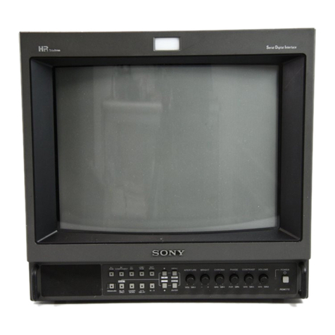
Sony Trinitron PVM-1954Q User manual

Trinitron® Color Video Monitor
Operating Instructions
Before operating the unit, please read this manual thoroughly and
retain if for future reference.
Mode d'emploi
A\'ant la mise.en ser\ ice de cet appareil, priere de lire
attentivement ce mode d'emploi et de la conser\'er pour tout
.reference ulterieure.
Owner's Record
The model and serial lUimLx'rs are located on the rear.
Record the model and serial numbers in the spaces provided
below. Refer to these numbers whene\'er vou call upon your
Sony dealer regarding this product.
Model No.. Serial No
This illustration shows l’\'M-1334Q.
Cette illustration represente le modele P\'M-l.'!.‘i4Q
1993 by Sony Corporation

Table of contents
iWARNING
To prevent fire or shock hazard, do
not expose the unit to rain or
moisture.
For the Customers in the USA
INFORMATION
This equipment has been tested and found to comply with
the limits for aClass Adigital de\’ice, pursuant to Part 15 of
the FCC Rules. These limits are designed to provide
reasonable protection against harmful interference when the
equipment is operated in acommercial environment. This
equipment generates, uses, and can radiate radio frequency
energy and, if not installed and used in accordance with the
instruction manual, may cause harmful interference to radio
communications. Operation of this equipment in a
residential area is likely to cause harmful interference in
which case the user will be required to correct the
interference at his own expense.
You are cautioned that any changes or modifications nc>t
expressly approx'ed in this manual could \'oid vour
authority to operate this equipment
For the Customer in Canada
This apparatus complies with the Class Alimits for radii)
noise emissions set out in Radio Interference Regulations.
Features 1
Location and function of parts and controls 2
Front panel 2
Rear panel .4
Using on-screen menus 6
Pow'er sources 8
Specifications 9
Precautions
On safety
•Operate the unit on 120 VAC only.
•The nameplate indicating operating voltage, power
consumption, etc. is located on the rear.
•Should any solid object or liquid fall into the cabinet,
unplug the unit and have it checked by qualified
personnel before operating it any further.
•Unplug the unit from the w^all outlet if it is not to be used
for several days or more.
•To disconnect the AC power cord, pull it out by grasping
the plug. Never pull the cord itself.
•The socket-outlet shall be installed near the equipment
and shall be easily accessible.
On installation
•Allow adequate air circulation to prevent internal heat
build-up.
Do not place the unit on surfaces (rugs, blankets, etc.) or
near materials (curtains, draperies) that may block the
ventilation holes.
•Do not install the unit in alocation near heat sources such
as radiators or air ducts, or in aplace subject to direct
sunlight, excessive dust, mechanical vibration or shock.
On cleaning
To keep the unit looking brand-new, periodicallv clean it
with amild detergent solution. Never use strong solvents
such as thinner or benzine, or abrasive cleansers since they
will damage the cabinet. As asafety precaution, unplug the
unit before cleaning it.
On repacking
Do not throw aw'ay the carton and packing materials. They
make an ideal container which to transport the unit. When
shipping the unit to another location, repack it as illustrated
on the carton.
If you have any questions about this unit, contact vour
authorized Sony dealer.

Features
HR (High Resolution) Trinitron picture tube
HR Trinitron tube provides ahigh resolution picture.
Horizontal resolution is more than 600 (PVM-1354Q/ 1954Q)
or 430 (PVM-1351Q) TV lines at the center of the picture.
Four color systems available
4he monitor can display PAL, SECAM, NTSC'os and
NTSCi r:* signals. The appropriate color system is selected
automatically.
*Asignal of NTSCTm is used for playing back NTSC
recorded yideo cassettes with ayideo tape recorder/
player especially designed for use with this system.
Blue only mode
In th ehj ue only mode, an apparent monochrome display is
obtained with all three cathodes dri\’en v\'ith ablue signal.
This facilitates color saturation and phase adjustments and
obserx’ation of VCR noise.
Analog RGB/component input connectors
Analog RGB or component (Y, R-Y and B-Y) signals from
\ideo equipment can be input through these connectors.
Y/C input connectors
The \ideo signal, split into the chrominance signal (C) and
the luminance signal (Y), can be input through this
connector, eliminating the interference between the tw(>
signals, which tends to occur in acomposite \ideo signal,
assuring video quality.
Beam current feedback circuit
The built-in beam current feedback circuit assures stable
white balance.
Comb filter
When NrSC video signals are receis'ed, acomb filter
actiwites to increase the resolution, resulting in fine picture
detail without color spill or color noise.
Automatic termination
(connector with VV mark only)
The input connector is terminated at 75 ohms inside when
no cable is connected to the loop-through output
connectors. When acable is connected to an output
connector, the 75-ohms termination is automaticalh released.
Underscan mode
The signal normally scanned outside of the screen can be
monitored in the underscan mode.
Note
When the monitor is in the underscan mode, the dark KGB
scanning lines may appear on the top ecige of the screen.
These are caused by an internal test signal, rather than the
input signal.
Horizontal/vertical delay mode
The horizontal and vertical sync signals can be checkeci
simultaneously in the H/V delay mode.
External sync input
When the EXT SYNC selector is in the on position, the
monitor can be operated on the sync signal supplied from
an external s\’nc generator.
Auto/manual degaussing
Degaussing of the screen can be performed automatically
when the power is turned on, or juanuallv b\' pressing the
DEGAUSS button.
On-screen menus
You can set color temperature, CHROM.V SE I' UP, and
other settings by using the on-screen menus.
Five menu languages
You can select the menu language from among the fix'e
languages on the menu.
EIA standard 19-inch rack mounting
By using an MB-502B (for PVN4-1354Q/ 1351Q) or SLR-103
(for PVM-1954Q) mounting bracket (not supplied), the
monitor can be iiKninted in an EIA standard 19-inch rack.
For details on mounting, see the instruction manual of the
mounting bracket kit.
SDI (Serial Digital Interface) kit
By using SDI kit, the monitoi' can displa\' SMPTE 259M 4:2:2
serial digital signal from adigital VTR. (e\. Sony 4:2:2 VTR)
SDI kit: 4:2:2 digital video board
Digital audit) board
1
English
Location and function of parts and controls
Front panel
[l jTally lamp
Lights up when the \'idee camera crmnected to this
monitor is selected, indicating tliat the picture is being
recorded.
POWER switch and indicator
Depress to turn the monitor on. The indicator will light
up in green.
[3] REMOTE indicator
Lights up when you set LiSLR PRLSHL to ON in the
menu, or when you connect asupplied cable to
REMOTE connector (No. 17 pin is ground). Ihe controls
on the front panel do not work when this indicator lights
up.
[4] VOLUME control
Eurn this control clockwise or counterck'ckwise to
obtain the desireci x'olume.
[5] CONTRAST control
Turn clockwise to make the contrast higher and
counterclockwise to make it lower.
PHASE control
this control is effectix eonly for the N1Sk ;and
NISCi r. color systems, burn clockwise to make the skin
tones greenish and countercUx kw ise to make them
purplish.
[7]CHROMA control
Turn clockwise to make the color intensity higher and
counterclockwise to make it lower.
[8]BRIGHT (brightness) control
Turn clockwise for more brightness and
counterclockwise for less.
[9] APERTURE control
Turn clockwise for more sharpness and
counterclockwise for less.
The APERTURE, CHROMA, PHASE control settings haye
no effect on the pictures of RGB signals.
mMENU (EXIT) button
Press to make the menu appear. Press to return to the
prev ious screen in the menu.
MENTER (SELECT) button
Press to decide aselected item in the menu.
Bl f(+)/ (-) buttons
Press to move the cursor () or adjust selected value in
the menu.
2

16:9 selector
Press (light on) for the signal of 16:9 picfiire.
HA/ DELAY selector
Press (light on) to observe the horizontal and vertical
sync signals at the same time.
The horizontal svnc signal is displayed in the left quarter
of the screen; the x'ertical sync signal is displayed near
the center of fhe screen.
A/RGB selector
When the LINE/RCB input selector is set to LINE (light
off), press this button (light on) to feed asignal through
the LI.XE Aconnectors.
When the I.IN'E/RCIB input selector is set to RGB (light
on), press this button (light on) to feed the RGB signal.
mUNDER SCAN selector
Press (light on) for underscanning. The display size is
reduced by approximately 5% so that four corners of the
raster are x'isible.
Ill BLUE ONLY selector
RESET button
Press (light on) to turn off the red and green signals. A
blue signal is displayed as an apparent monochrome
picture on the screen. This facilitates "chroma" and
"phase*" control adjustments and observation of VCR
noise.
*"Phase" control adjustment is effectix eonh’ for the
NTSC signals.
Press to reset the setting in the menu,
[17] DEGAUSS button
Press this button momentarily. The .screen will he
demagnetized. Wait for 10 minutes or more before
activating this button again.
OEXT SYNC (external sync) selector
Keep this button in the off pcisition (light off) U) operate
the monitor on the sync signal from the displayed \ideo
signal.
Keep this button in the on position (light on) to operate
the monitor on an external sync signal fed through the
EXT SYNC connector on the rear panel.
[il LINE/RGB input selector
Select the program to be monitored. Keep this buttern in
the off position (light off) to feed asignal through the
LINE A, LINE Bor LINE Cconnectors. Keep this button
in the on position (light on) to feed asignal through the
RGB connectors.
C/SDI selector
When the LINE/RGB input selector is set to LINE (light
off), press this button (light on) to feed asignal through
the LINE Cconnectors.
When the LINE/RGB input selector is set to RGB (light
on), press this button (light on) to feed the SDl signal
(optional board is needed).
B/COMPONENT selector
When the LINE/RGB input selector is set to LINE (light
off),'pres.s this button (light on) to feed asignal through
the LINE Bconnectors.
When the LINE/RGB input selector is set to RGB (light
on), press this button (light on) to feed the component
signal.
3
English

Location and function of parts and controls
Rear panel
LINE A
VIDEO
IN OUT
LINE B
VIDEO
IN OUT
t-y»i
LINE C
OUT REMOTE
IN OUT 1IN OUT 1IN OUT 1IN OUTII
®@)
R/R-Y 1G/Y 1B/B-Y AUDIO
'ONENT )l
OUT
EXT SYNC
(The Vv mark indicates aLitomatic termination.)
[f] AC IN socket
Connect the supplied .AC power cord to this socket and
to awall outlet.
[2] LINE A, LINE Bconnectors
Two groups (A and B) of line input connectors tor the
composite video and audio signals and their loop-
through output connectors.
To monitor the input signal fed through these
connectors, keep the LIXE/RCB selector in the I.IXF,
position (light off) and press the A/RGB or
B/COMPONENT selector (light on) on the front panel.
VIDEO IN (BNC)
Connect to the video output of a\ideo equipment, such
as aVCR or acolor \ideo camera. For aloop-through
connection, connect to the \'ideo output ot another
monitor.
VIDEO OUT (BNC)
Loop-through output of the \TDEO IN connector.
Crrnnect to the video input for a V'CR or another
monitor.
When the cable is connected to this connector, the
7h-ohms termination of the input is automatically
released, and the signal input to the VIITFC) IN'
connector is output from this ccmnector.
AUDIO IN (phono jack)
Connect to the audio output of aVCR or to a
microphone via asuitable microphone amplilier. For a
loop-through connection, connect to the audio output ot
Manother numitor.
AUDIO OUT (phono Jack)
Loop-thrcnigh output of the AUDIO IN jack. Connect to
the audio input of aVCR or another monitor.
[3] LINE Cconnectors
Y/C IN (4pin mini DIN)
Connect to the Y/C separate output of avideo camera,
VCR or other video equipment.
Y/C OUT (4pin mini DIN)
Loop-through output of the Y/C IN connector. Connect
to the Y/C separate input of aVCR or another monitor.
When the cable is connected to this connector, the
7b-ohms termination ot the input is automaticallv
releasecT and the signal input to the Y/C IN connector is
output from this connector.
AUDIO IN (phono Jack)
Connect to the audio output of aV'CR or amicrophone
(through asuitable micrrrphrrne amplifier).
AUDIO OUT (phono Jack)
l.oop-through output of the AUDIO IN connector.
Connect to the audio input of aV'CR or another monitor.
[4j REMOTE connector (20pin)
Connect to the tally output of acontrol console, special-
effect generator, etc. The tallv lamp on the front panel
will be turned on and off bv the connected equipment.
This connector can be used for connecting aremote
controller. For the pin assignment ot this connector, see
"Specifications" on page 10.

[5] RGB/COMPONENT connectors
RGB signal or component signal input connectors and
their loop-through output connectors.
To monitor the input signal fed through these
connectors, keep the LINE/RCB selector in the RGB
position (light on), and press the A/RGB (rr
B/COMPONENT selector (light r)n) on the front panel.
R/R-Y IN, G/Y IN, B/B-Y IN (BNC)
When the EXT SYNC selector on the front panel is in the
off position (light off), the monitor operates on the sync
signal from the G/Y channel.
To monitor the RGB signal
Connect to the analog RGB signal outputs of ax'ideo
camera.
Ta_monitor the component signal
Connect to the R-Y/Y/B-Y component signal (Hitputs of
aSony Betacam \'ideo camera.
R/R-Y OUT, G/Y OUT, B/B-Y OUT (BNC)
Loop-through outputs of the R/R-Y IN, G/Y IN, B/B-Y
IN connectors
For RGB signal
Connect to the anak>g RGB signal inputs of avideo
printer or another monitor.
For component signal
Connect to the R-Y/Y/B-Y component signal inputs of a
Betacam x’ideo recorder.
When the cables are connected to these connectors, the
75-ohms termination of the inputs is automatically
released, and the signal inputs to the R/R-Y IN, G/Y IN,
B/B-Y IN connectors are output from these connectors.
AUDIO IN (phono jack) '
Connect to the audio output of \ideo equipment when
the analog RGB or component signal is input.
AUDIO OUT (phono jack)
Loop-through outputs of the AUDIO IN connector.
[U EXT SYNC (external sync) connectors
To use the sync signal fed through this connector, press
the EXT SYNC selector (light on).
IN (BNC)
When this monitor operates on an external svnc signal,
connect the reference signal from async generator to this
connector.
OUT (BNC)
Loop-through output of the EX ESYNC IN connector.
Connect to the external svnc input of video equipment U)
be synchronized with this monitor.
When the cable is connected to this connector, the 75-
ohms termination of the input is released, and the signal
input to the IN connector is output from this connector.
5
English

Using on-screen menus
The flow chart shows the different levels of on-screen
menus that you can use to make various adjustments and
settings. The boxed number is for instructions on the next
page.
[Tj Main menu
L3] color TEMP/BAL menu
[8] ADJUST GAIN screen
[9] ADJUST BIAS screen
[il COLOR TEMP RANGE menu
g] CAPTION VISION menu
5j USER CONFIG 1menu
[H] COLOR SYSTEM DISPLAY menu
111 358 TRAP FILTER menu
mSUB CONTROL screen
PUSER PRESET menu iTs] PRESET ADJUST screen
in VHOLD screen
ill COMPONENT LEVEL menu
HNTSC SETUP LEVEL menu
[il ACC menu
HLANGUAGE menu
6

Operating through menus
There are fi\'e buttons for menu operations on the front of
the monitor. To display the main menu, first press MENU.
The buttons you can use appear at the bottom of the menu
screen.
Functions of the buttons
Button To select menu To adjust menu item
item selected
MENU
EXIT
ENTER
SELECT
T
return to the
previous menu
decide aselected
item
move the cursor
() upwards
mo\'e the cursor
() downwarcfs
return to the previous
menu
select an item
increase selected value
decrease selected wilue
reset current adjustment
value to the factory
setting
(The abox'C items in white type correspond to the marks in
the menu.)
front of monitor
B' C;
COMPONENT SOI
LINE/ EXT
RGB SYNC
..
ami
BLUE UNDER HV
ONLY SCAN DELAY
MENU
rilHLli
lan
ENTER
reset buttons for
button menu
operations
[T] Main menu
Select an item and press ENTER to go to the following
menu.
[2]CHROMA SET UP menu
Set to ON to adjust the internal decoder for CHROMA
and PHASE (NTSC signal only) after AUTO ADJUST
(E). '|OFF|
[3]COLOR TEMP/BAL menu
Select the color temperature from among 65()0K, 9300K
and USER. USER is set to 6S00K in the factory setting.
You can acfjust or change the color temperature in USER
mocfe (a measuring instrument is needed), [h.SOOK]
0CAPTION VISION menu
The iTionitor can display the signal with Caption Vision.
To display it, select the caption Upe in this menu.
[OFF]
[5]USER CONFIG 1menu
Select an item tci adjust. To go to the USER COXFlCi 2
menu, select NEXT P.ACE.
[6] USER CONFIG 2menu
Select an item to adjust. To go to the USER CONFIG 1
menu select PREVIOUS PAGE.
[7] AUTO ADJUST screen
Select the color bar signal (full, SMPTE, ElA) and press
ENTER to start auto adjusting for CHROMA SET UP
(NTSC signal only).
d] ADJUST GAIN screen
Adjust GAIN in USER mode.
[g] ADJUST BIAS screen
Adjust BIAS in USER mode.
01 COLOR TEMP RANGE menu
Select the color temperature range in USER mode.
[50U0K40000K]
[H] COLOR SYSTEM DISPLAY menu
Sefect the color swstem display mode. In AUTO, the kind
of color system being used appears on the screen each
time you change the signal input. [AUTO]
111 358 TRAP FILTER menu
Color spill or color noise may be eliminated if you select
ON (N rSCv^s signal only). [OFF]
0SUB CONTROL screen
You can finely adjust the controls on the front panel.
CONTR.AST, BRIGHT, CHROMA and PHASE control
has aclick at the center of its adjustment range. You can
acJjust the setting /if the click position u'ith this feature.
HU USER PRESET menu
You can preset each control to adesired level and set it.
If you set USER PRESE Tt/i ON, the REMOTE indicator
lights up and the controls on the front panel do not
work. The monitor operates with the internal memory
settings. For adjustment, select PRESET ADJUST. [OEF]
01 PRESET ADJUST screen
Adjust CONTRAS! ,BRIGHT, CHROMA, PHASE,
VOLUME, APERTURE in USER PRESE I
.
01 VHOLD screen
Adjust the vertical hold if the picture rolls xertically.
When vou cannot read the display, select the input that
is not connected.
01 COMPONENT LEVEL menu
Select the component level from among three modes.
NIO/SMPTE for 100/0/ 11)0/0 signal
BETA 7.5 for 100/7.5/75/7.5 signal
BETA 0for 100/0/75/0 signal [BETA 7.5|
01 NTSC SETUP LEVEL menu
Select the NTSC setup le\ el from two modes. Ihe 7.5
setup lex'el is mainly used in north America. The 0setup
lex'el is mainly used in japan. [7.5]
01 ACC menu
Set ACC (Auto Color Control) circuit on or off. When the
fine adjustment is needed, set .ACC to OFF. N'ormalh’ set
it to ON. |ON|
mLANGUAGE menu
You can select the menu language from among the fix e
languages (English, German, French, Italian, Spanish) on
the menu. lENGLISI 1]
(1 Iindicates the factiirx setting position.) 7
English

Power sources
House current
Connect the AC power cord (supplied) to the AC IN socket
and to <1 Weill outlet.
To connect an AC power cord securely with an AC plug holder
AC IN socket
Flue the pou’er cord into the AC I.N socket. Ihen, <itt<ich the
AC plus holder (supplied) on top of the AC power coref.
2
Slide the AC plug holder o\'er the cord until it connects
with the attached holder.
To remove the AC power cord
Full out AC plus holder b\’ squeezing the left and right sicies.
8

Specifications
Video signal
Color system
Resolution
Aperture correction
Frequency response
Synch ronization
PAL, SECAM, XTSC^ NTSCA r.
600 T\' lines (IA'V1-1434Q/ I334Q)
430 TV lines (PVM-1331Q)
0dB-+6.0dB
LINE O.OMHz (--3 dB)
RGB 10.0 MHz (-3d B)
AFC time constant 1.0 msec.
Picture performance
Normal scan
Underscan
7' ;ox er scan of CR'L effectix escreen
area
3'.-< underscan of CRT effectiye screen
H. linearity
V. linearity
Conyerirence
area
l.ess than (S.O'i (typical)
Ia'ss than 7.0'; (typical)
Central area:
0.6 mm (typical) (PViVL1334Q)
0.7 mm (typical) (P\'M-I934Q)
Peripheral area:
0.8 mm (typical) (PVM-L334Q)
1.3 mm (typical) (PVM-1934Q)
H: 1.0',;, V: 1.3'v
Higli x'ciltage regulation
3.57; (PVM-1354Q/133iQ)
4.0's (PV.M-1934Q)
S.MPTF-C phosphor (PV.M-1334Q/
14.34Q)
P22 phosphor (I’VM-I331Q)
6,300K/9,300K (+8MPCD), selectable
USER (3200K- lOOOOK, factory setting
is 6500K)
Raster size stability
CRT
Color temperature
inputs and Outputs
Inputs 3VC IN: 4-pin mini DIN connector
(See the pin assignment on the next
page.)
\H3EO IN:BNC connector
IVp-p ±6dB, sx'iic negatix'e
AUDIO IN: phono jack, -3 dBs, more
than 47k ohms
R/R-Y, G/Y, B,'15-Y IN: BNC
connector
R, G, Bchannels: 0.7 \'p-p, ±6dB
Sync on green: 0.3 Vp-p, negatix’e, 73
olims terminated
R-Y, B-Y channels: 0.7 Vp-p, ±6 dB
3' channel: 0.7 Vp-p, ±6dB
(Standard color bar signal of 73'/i
chrominance)
EXT SYNC IN: BNC connector
Composite sync 4Vp-p, ±6 dB,
negatix'e
Loop-through outputs
3'/C OU 1:4-pin mini DIN connector
VIDEO OUT: BNC connector, 73
ohms terminated
AUDIO OUT: phono jack
Output lex'el 0.8 \V
R/R-Y, G/Y, B/B-Y OUT: BNC
connector, 73 ohms terminated
,EXT SYNC OUT: BNC connector, 73
ohms terminated
Remote input REM(,)TF.: 20-pin connector (See the
pin assignment on the next page.)
General
Bower consumption Approx. 99 VVh (inch SDI)
/Xpprox. 90 VVh (without, SDI)
(BVM-I334Q/133IQ)
Approx. 123 Wh (inch SDI)
Approx. 113 VVh (without. SDI)
(PVM-19.34Q)
Bower rec]uirements 120 VAC, 30/60 Hz
Operating temperature range
0-3a C
Storage temperature range
-10--r40'’C
0-90';;
BV.M-1334Q/1351Q
Approx. 346 x340 x41 1.3 mm
(w/ h/ d)
(13 '/.- X13 '/: X16 Vi Inches)
BVV1-19.34Q
Approx. 430 x437.3 x303 mm
(w/h/d)
(17 '/i X18 '/f X19 /,, inches)
not inch projecting parts and controls
BVM-1334Q/1.351Q
Approx. 16.7 kg (36 lb 14 oz)
BVM-19.34Q
Approx, 30 kg (66 lb 2oz)
Accessory supplied AC power cord (I
)
AC plug holder (1
)
Tally label (1)
Cable with a20-pin connector (1
)
Design and specifications are subject to change without
notice.
Humidity
Dimensions
Mass
9
English

Specifications
Pin assignment
Y/C IN connector (4-pin mini DIN)
Pin No. Signal Description
1Y-input 1Vp-p, sync negative, 75
ohms
2CHROMA sub-
carrier-input
300 mVp-p, burst
Delay time between Yand C:
within 0±100 nsec., 75 ohms
3GND for Y-input GND
4GND for
CHROMA-input GND
REMOTE connector (20-pin)
8^3^
/0O0N, \
//-O 4914 leX \
/{'0O00\\
//0510 15 19 \\
12Oo0 0
v\°61•, 16 20 //
0o00/1
\12 17 /j
X0o0V
Pin No. Signal Wire color
1Blue onh’ Brown
2H/V DELA't Red
3MAIN/SUB^^' Orange
4EXT SYNC Yel Unv
5DEGAUSS Green
6Rch ON70FF'^‘ Blue
7TALL3' Furple
8LINE BGrey
9GND White
10 GND Black
11 GND Pink
12 GND Light Blue
13 LINE ASpiral Orange
14 LINH/RGB Spiral Yellow
15 GND Spiral Green
16 Lch ON/OFF^^^ Spiral Blue
17 REMOTE Spiral Purple
18 LINEC Spiral Grey
19 UNDER SCAN Spiral Pink
20 16:9 Spiral light Blue
(* For digital audio control)
10

AVERTISSEMENT Table des matieres
Afin d'eviter tout risque d'incendie ou
d'electrocution, ne pas exposer cet
appareil ala pluie ou aI'humidite.
De hautes tensions dangereuses sont piesentes aI'intcrieur
de rappareil. Ne pas ou\'rir le coffret. Confier tout travail
d'entretien uniquement aun personnel qualifie.
Pour ies utilisateurs au Canada
Cet appareil est conforme aux normes Classe Apour bruits
radioelectriqucs, specifies dans le Reglement sur le
broLiillage radioelectrique.
Caracteristiques 1
Emplacement et fonction des composants
et des commandos 2
Panneau avant 2
Panneau arriere 4
Utilisation des menus aftiches aI'ecran 6
Modes d'alimentation 8
Specifications 9
Precautions
Securite
•Faites uniquement fonctionner I'appareil sur secteur de
120 volts (CA).
•I-a plaquette signaletique indiquant la tension, la
consommation, etc,, est situee aI'arriere de I'appareil.
•Si un liquide ou un solide venait as'introduire a
I'interieur du chassis, debranchez le cordon
d'alimentation et faites-le \'erifier par un tcchnicien
competent a\ ant de le remettre en service,
•Debranchez I'appareil au ni\ eau de la prise secteur si
\ous pre\-ovez de ne pas I'utiliser pendant plusieurs jours
ou dax antage.
•Pour debrancher le cordon d'alimentation, saisissez-le par
la fiche et ne tirez jamais sur le cordon proprement dit.
•L.a prise secteur doit etre installee aproximite de
I'appareil et etre aisement accessible.
Installation
•Veille/ aassurer une circulation d'air suffisante pour
eviter toute surchauffe aI'interieur de I'appareil.
•Ne place/ pas I'appareil sur des surfaces textiles (tapis,
coin ertures, etc.) ni aproximite de rideaux ou de
draperies susceptibles d'obstruer Ies orifices de
xentilation
•N'installez pas I'appareil aproximite de sources de
chaleur comme un radiateur ou une bouche d'air chauct,
ni dans un endroit expose au rayonnement solaire direct,
ades poussieres excessix’es, ades x'ibrations ou ades
chocs mecaniques.
Entretien
Pour garder aI'appareil I'aspect du neuf, nettoyez-le
regulierement aI'aide d'une solution detergente douce.
N'utilisez jamais de soK ants tels que de I'alcool ou de
I'essence ni de nettoyants abrasifs sous peine de ternir le fini
de I'appareil. Par mesure de securite, debranchez I'appareil
a\ ant de le netUn er.
Remballage
Conserve/ le carton d'emballage et Ies materiaux de
conditionnement, car ils constituent une protection ideale en
vLie du transport de I'appareil. Lot sdu transport de
I'appareil, remballe/-le comme illustre sur le carton.
Pour toute question au sujet de cet appareil, consultez un
distributeur Son\' agree.

Caracteristiques
Tube image Trinitron aHR (Haute Resolution)
Lc tube image Trinitron aHR assure une image ahaute
resolution. La resolution horizontale est de plus de 600
lignes TV (PY\1-1354Q/ 1954Q) on de 450 lignes TV (PVM-
1351Q) au centre de Limage.
Quatre systemes couleur disponibies
Le moniteur pent afficher les signaux PAL, SECAM,
NTSCsas et NTSC4,r. s. Le svsteme couleur approprie est
selectionne automatiquement.
*Le signal de NTSCj.r. est utilise pour la lecture de
cassettes \'ideo enregistrees suix'ant le systeme NTSC sur
un magnetoscope specialement conqu pour ce systeme.
Mode d'affichage en bleu uniquement
En matte d'affichage bleu, I'affichage est apparemment
monochrome, les tixiis cathodes etant entrainees par un
signal bleu. Cela facilite le reglage de saturation de la
couleur, le reglage de phase et l'obser\’ation des
interferences en provenance du magnctoscope.
Connecteurs d'entree analogiques RGB/
composant
Les signaux RGB analogiques et composants (Y, R-Y et B-Y)
d'un appareil \'ideo peux’cnt etre rc<;us via ces connecteurs.
Connecteurs d'entrees de luminance/
chrominance (Y/C)
Le signal video, divise en signal de luminance (Y) et en
signal de chrominance (C), pent etre refu via ce connecteur,
ce qui apour effet d'eliminer les interferences entre les deux
signaux qui ont tendance aapparaitre dans un signal video
composite et de garantir la qualite des images.
Circuit de retroaction automatique du courant
de faisceau
L.e circuit de retroaction automatique du courant de faisceau
assure une compensation stable des blancs.
Filtre en peigne
Lorsque des signaux video NTSC sont requs, le filtre en
peigne entre en serx ice afin d'augmenter la definition et
d'obtenir des images finement detaillees, sans taches de
couleur ni parasites.
Terminaison automatique
(uniquement connecteur avec marque W)
Le connecteur d'entree est termine a75 ohms aI'interieur,
dans le cas oil aucun cordon n'est raccorde aux conni^cteurs
de sortie en boucle directe. Lorsqu'un cable est branche sur
le connecteur de sortie de type BNC, la terminaison de 75
ohms est relachee automatiquement.
Mode de sous-balayage
Le signal normalement balave en-dehors de I'ecran pent etre
surx eille en mode de sous-balavage.
Les lignes de balax age RGB sombres qui peux'ent apparaitre
sur le bord superieur de I'ecran lorsque le moniteur se
troux een mode de sx'us-balavage sont causees par un signal
d'essai interne et non par le signal d'entree.
Mode de retard horizontal/vertical
Les signaux de synchronisation horizontale et x'erticale
peux'ent etre xerifies simultanement en mode de retard H/
V.
Entree de synchronisation externe
Lorsque le selecteur EXT SYNC est en position ON, le
moniteur pent fonctionner sur le signal de synchronisation
fourni depuis un generateur de synchronisation externe.
Demagnetisation automatique/manuelle
La de-magnetisation de Limage pent se fairc
automatiquement lorsque I'alimentation est endcnchce ou
alors manuellement en appuvant sur la touche DEGAUSS.
Menus affiches sur I'ecran
Vous pouve/ regler les parametres temperature couleur,
CHROM.A SET UP, etc., au moven des menus affiches sur
I'ecran.
Cinq langues d'affichage des menus
V'ous poux ez selectionner I'une des cinq langues d'affichage
des menus.
Montage sur etagere de 19 pouces de normes
EIA
Le moniteur pent etre installc- sur une etagere de 19 pouces
de nixrmes EIA mox'ennant I'adaptation d'un rail-glissiere
MB-5()2B (pour PVM-L354Q/1351Q) ou SLR-103 (pour
PVM-1954Q) (non fournis). Pour les details relatifs au
montage, xoir ie mxxde d'emploi de I'adaptation d'un
rail-glissiere.
Kit SDI (interface numerique serielle)
;\x ec le kit SDI, le moniteur pent afficher le signal
numerique seriel SMPTE 259 M4:2;2 d'un magnetoscope
numerique (p.ex. magnetoscope Sony 4:2:2),
Kit SDI: carte xideo numeric|ue 4:2:2
carte audio numerique
1
Frangais

[T] Temoin de signalisation
II s'allume des quo la'camdfa \'ideo raocordeo acot
apparcil ost sdloctionndo, indiquant par la quo lo;- iniaqos
sont onregistrdos.
Interrupteur et indicateur de mise sous tension
(POWER)
Appuvoz sur cot intorruptour pour mottro lo moniteur
sous tension. L'indicatour \ort s'allumo.
[3] Indicateur REMOTE
Cot indicateur s'allumo lorsquo \cnis ro’gloz
PREREGLAGE UTIEISAT elk sur OLI dans lo menu ou
lorsquo \'Ous connoctoz un cable kHirni au connoctour
REMOTE (la brocho n" 17 ost la masse). Los commandos
situbos sur lo pannoau frontal sont inopbrante's lorsquo
cot indicateur ost allumb.
Reglage du volume (VOLUME)
Tournoz. cotto commando dans lo sons dos aiguilles
d'uno montro ou dans lo sons contrairo pour obtonir lo
oolumo dbsirb.
Jteglage du contraste (CONTRAST)
'Eournoz. cotto commando dans lo sons dos aiguilles
d'uno montro pour augmontor lo contraste do I'imago ot
dans lo sons contrairo poiu' lo diminuor.
[6] Reglage de phase (PHASE)
Cotto commando n'est opera tionncllo quo pour les
sostbmos coulour NTSCrs^ ot NTSCi.o. Tournoz. dans lo
sons dos aiguilles d'uno montro pour fairo oircr la
coulour chair au vert ot dans lo sons contrairo pour la
rondro plus rouge.
Reglage de la chrominance (CHROMA)
I'ournoz dans lo sons des aiguilles d'uno montro pour
augmontor I'intonsitb dos coulours ot dans lo sons
contrairo pour la diminuor.
[U Reglage de la luminosite (BRIGHT)
Tournoz dans lo sons dos aiguilles d'uno montro pour
augmontor la luminosite et dans lo sens contrairo pour la
diminuor.
[9] Reglage d'ouverture (APERTURE)
Tournoz dans lo sons dos aiguilles d'uno montro pour
augmontor la nottotb do I'imago ot dans lo sons contrairo
pour la diminuor.
Remarque
Los ro'glagos APERTURE, Cl IROMA, PHASE n'ont aucun
offot sur los images des signaux RGB.
|j^ Touche MENU (EXIT)
Appuyoz sur cotto touche pour fairo apparaitro lo menu.
.Vppuvoza noiu'oau pour ro\'onir aI'bcran prbebdont
dans lo menu.
2

MTouche ENTER (SELECT)
Appuyez sur cettc touche pour selecHonner un
parametre dans le menu.
[ill Touches (+)/4^(-)
Appuyez sur ces touches pour deplacer le curseur (
)
ou regler le parametre selectionne dans le menu,
111 Selecteur 16:9
Appuyez sur cette touche (temoin allume) pour le signal
d'une image 16:9.
[i3 Selecteur de retard horizontal/vertical (H/V
DELAY)
Appuyez sur cette touche (temoin allume) pour observer
simultanement les signaux de synchronisation
h.orizontale et verticale.
Le signal de synchronisation horizontale est affiche dans
le quart gauche de I'ecran tandis que le signal de
synchronisation verticale est affiche pres du centre de
I'ecran.
[Ts] Selecteur de sous-balayage (UNDER SCAN)
Appuyez sur cette touche (temoin allume) pour
proceder au sous-balayage. Les dimensions de
I'affichage sont reduites de 5"li environ, de sorte que les
quatre coins de la trame sont x'isibles.
jiel Selecteur d'affichage bleu uniquement (BLUE
ONLY)
Touche RESET
Appuyez sur cette touche (temoin allume) pour couper
les signaux rouge et \'ert. Ln signal bleu est affiche
comme une image apparomment monochrome sur
I'ecran, Cette fonction facHite le'rbglage de la
"chrominance" et le reglage de "phase*" ainsi que
robser\'ation des interferences pixn’enant du
magnetoscope.
*Le reglage du contrdle de phase n'est possible que
pour les signaux NTSC.
Appuvez sur cette touche pour reinitialiser le reglage
dans le menu.
Hzl Touche de demagnetisation (DEGAUSS)
Enclenchez cette touche momentanement. L'ecran va
etre demagnetise. Attendez 10 minutes avant de
reenclencher cette touche.
[ill Touche de synchronisation externe (EXT SYNC)
Maintenez cette touche en position OFF (temoin eteint)
pour faire fonctionner le moniteur sur le signal de
synchronisation prox enant du signal video affiche,
Maintenez cette touche en position ON (temoin allume)
pour faire fonctionner le moniteur sur un signal de
synchronisation externe fourni via le connecteur EXT
SYNC situe sur le panneau arriere.
[Tl Selecteur d'entree de ligne (LINE/RGB)
Selectionnez le programme acontroler, Maintenez cette
touche en position OFF (temoin eteint) pour faire passer
un signal via les connecteurs LINE A, LINE Bou LINE
C. Maintenez cette touche en position ON (temoin
allume) pour faire passer un signal \ia les connecteurs
RCB.
il Selecteur OSDI
Lorsque le selecteur d'entree LINE/RGB est en paosition
LINE (temoin eteint), appauvez sur cette touche (temoin
allume) paour faire paasser un signal via les connecteurs
LINE C, Lorsque le selecteur d'entree LINE/RGB est en
position RGB (temoin allume), apapauyez sur cette touche
(temoin allume) paour faire paasser le signal SDI (la carte
optionnelle est reejuise).
mSelecteur B/COMPONENT
Lorsque le selecteur d'entree LINE/RGB est en position
LINE (temoin eteint), appuyez sur cette touche (temoin
allume) pour faire passer un signal via les connecteurs
LINE B. Lorsque le selecteur d'entree LINE/RGB est en
paosition RGB (temoin allume), apapauyez sur cette touche
(temoin allume’) paour faire paasser le signal du
compaosant.
HSelecteur A/RGB
Lorsque le selecteur d'entree LINE/RGB est en position
LINE (temoin eteint), appuyez sur cette touche (temoin
allume) pour faire passer un signal \-ia les connecteurs
LINE A. Lorsque le selecteur d'entree LINE/RGB est en
paosition RGB (temoin allume), appuyez sur cette touche
(temenn allume) penir faire passer le signal RGB,
Franqais

Emplacement et fonction des composants et des commandes
Panneau arriere
LINE A
VIDEO
IN OUT
AUDIO
IN OUT
LINE B
VIDEO
IN OUT
HOT
AUDIO
IN OUT
LINE C
AUDIO
IN OUT
REM'
pTE
IN OUT IN OUT IN OUT [IN OUT
®0m
R,'R-Y G.'Y LB/B-Y AUDIO 1
RGB,'COM ^ONENT ]iSil
r
(L.1 marque Windiqiie la terminaison aiitomatiquc.)
[T] Prise d'alimentation (AC IN)
Connectez lo cordon d'alimoiitation secteur toiirni a
cotte prise et aune prise murnle.
[2] Connecteurs de ligne Aet B(LINE A, LINE B)
Deux groupes de connecteurs d'entree de ligne (A et B)
sont destines aux signaux video composite et audio ainsi
qu'a leurs connecteurs de sortie en houcle directe.
Pour surveiller le signal d'entree fourni par cos
connecteurs, maintenez le selecteur LINE/RGB en
position LINE (temoin eteint) et appuvez sur le selecteur
A/RGB ou B/COMPONHNT (temoin allume) sur le
panneau frontal.
VIDEO IN (BNC)
Raccordez ce connecteur ala sortie video d'un appareil
video tel qu'un magnetoscope ou une camera x'ideo
c<Hileur. Pour une connexion en boude directe,
raccordez-le ala sortie video d'un autre moniteur.
VIDEO OUT (BNC)
Sortie en boude directe du connecteur VIDEO IN.
Raccordez ce connecteur aI'entree x'ideo du
magnetoscope ou d'un autre moniteur,
Lorsquo le cable est branche ace connecteur, la
terminaison de 7b ohms de I'entree est relachee
automatiquement et le signal entre au connecteur
VdlOEO IN sort \ia ce connecteur.
4
AUDIO IN (prise phono)
Raccordez ce connecteur ala sortie audio d'un
magnbtoscope ou d'un microphone par I'intermediaire
d'un amplificateur de microphone approprie. Pour une
ct>nnexion en boude directe, racccirdoz ce connecteur a
la sortie audio d'un autre moniteur,
AUDIO OUT (prise phono)
Sortie en boude directe de la prise AUDIO IN.
Raccordez ce connecteur ala sortie audio d'un
magnetoscope ou d'un autre moniteur.
[3J Connecteurs LINE C
Y/C IN (miniconnecteur DIN a4broches)
Raccordez ala sortie distmcte Y/C d'une camera video,
d'un magnetoscope ou d'un autre appareil video.
Y/C OUT (miniconnecteur DIN a4broches)
Sortie en boude directe du connecteur Y/C. Raccordez a
I'entree ciistincte Y/C d'un magnetoscope ou d'un autre
moniteur.
Lor.sque le cable est branche ace conneceur, la
terminaison de 7.S ohms de I'entree est relachee
automatiquement et le signal entre au connecteur Y/C
IN sort via ce connecteur.
AUDIO IN (prise phono)
Raccordez ala sortie audio d'un magnetoscope ou d'un
microphone (via un amplificateur de microphone
approprie).
AUDIO OUT (prise phono)
Sortie en houcle directe du connecteur AUDIO IN,
Raccordez aI'entree audio d'un magnetoscope ou d'un
autre moniteur.

[4] Connecteur REMOTE (20 broches)
Raccordez ce cimnecteur ala sortie do sii^naiisation
d'line console de contrdle, d'rin generateur d'effets
specianx, etc. Le temoin de signalisation situe siir le
panneau frontal sera alliime et eteint par I'appareil
connecte. Ce connecterir pent etre ntilise en ene de la
connexion d'nn dispositit de teleconimande. I’onr
I'assignation des broches de ce connecteur, voir
"Specifications" ala page 10.
[5] Connecteurs RGB/COMPONENT
Connecteurs d'entree de signal de composant ou de
signal RGB et leurs connecteurs de sortie en boiicle
directe.
Pour contrdler le signal d'entree tourni \ia ces
coHuecteurs, maintenez le selecteur l..lNP/RGBen
position RGB (temoin allume) et appuc ez sur le
selecteur A/Rt.B ou B./COMPONPNT (temoin allume)
sur le panneau frontal.
R/R-Y IN, G/Y IN, B/B-Y IN (BNC)
Porsque la touche HX ISh'NC situee sur le panneau
frontal. est en position C')l'l- (temoin eteint), le moniteur
tbnctionne sur le signal prox enant de la chaine G/Y.
Pour contrdler le signal RGB.
Raccordez aux sorties analogiques de signal RGB d'une
camera xideo.
Pour contrdler le signal composant.
Raccordez aux sorties de signal composant R-'t'/'t'/B-Y
d'une camera eideo Betacam Seine.
R/R-Y OUT, G/Y OUT, B/B-Y OUT (BNC)
Sorties en boucle directe des connecteurs R/R-Y IN, C./Y
IN, B/B-Y IN.
Pour le signal RGB.
Raccordez. aux entrees analogiL|ues de signal RGB d'une
imprimante video ou d'un autre moniteun
Pour le signal composant.
Raccordez aux entrees de signal composant R-Y/Y/B-Y
d'un camescope Betacam Son\
.
Lorsque les cables sont branches sur ces connecteurs, la
terminaison de 7h ohms de I'entree est relachee
automatiquement et le signal entre \ia connecteurs R/R-
YhN, G/Y IN, B/B-Y IN sort \ia ces connecteurs.
AUDIO IN (prise phono)
Raccordez ala sortie audio d'un appareil \idcYi lorsque
le signal analogique RGB ou composant est entre.
AUDIO OUT (prise phono)
Sortie en boucle directe du connecteur AUDIO IN.
[6]Connecteurs de synchronisation externe (EXT
SYNC)
Pour Litiliser le signal de synchronisation fourni par ce
conneedeur, appuvez sur le selecteur PX INC (temoin
allume).
IN (BNC)
Lorsque ce moniteur tonctionne sur un signal de
synchronisation externe, connectez le signal de reference
d'un generateur de synchronisation ace connecteur.
OUT (BNC)
Sortie en boucle directe du connecteur EXT SYNC IN.
Raccordez ce connecteur aI'entree de synchronisation
externe de I'appareil video asynchroniser avec ce
moniteur.
Lorsque le cable est branche sur ce connecteur, la
terminaison de 75 ohms de I'entree est relachee et le
signal entre via le connecteur IN sort \’ia ce connecteur.
5
Fran^ais

utilisation des menus affiches sur I'ecran
Le tableau ci-dessous indiquc les differents niveaux de
menus d'affichage que \(his pcun ez utiliser pour proceder
aux divers reglages et selections. L.e numero encercle
renvoie aux instructions (l.e numero encercle ren\'oie aux
instructions) de la page suix ante.
rn Menu principal L2] Menu REGLAGE CHROMA
MENU REGLAGE CHROMA [
REGLAGE CHROMA NON i
TEMP COULEUR/BAL OU 1 \
SOUS-T 1TRAGE -REGLAGE AUTO i
CONF IG UT 1L1SATEUR
'SELECT 1
'•SELECT ‘-.--j
f7l Ecran REGLAGE AUTO
[3] Menu TEMP COUEUR/BAL
lEMP COULEUR/BAL
6500K
9300K
UT 1LISATRt'BAL BLANC)
-REGLAGE GAIN
REGLAGE BIAS
PLAGE TEMP COULEUR
SELECT
)8] Ecran REGLAGE GAIN
9j Ecran REGLAGE BIAS
,iOi Menu PLAGE TEMP COULEUR
14 Menu SOUS-TITRAGE
SOUS- TITRAGE
NON
SOUS-T ITRAGE
1
SOUS TITRAGE
2
TEXTE 1
TEXTE2
i»SELEC1
I
g] Menu CONFIG UTILISATEUR 1
ICONF IG UT
I
LISATEURI ^I
AFF SYSTEMS COULEUR
FIlTRE PIEGE 358
REGLAGE SECONOAIRE
PREREGLAGE UTILISATEUR
STABILITE VERTICALS
PAGE SUIVANTE
ill] Menu AFF SYSTEME COULEUR
[12] Menu FILTRE PIEGE 358
•SELECT I— MEcran REGLAGE SECONOAIRE
6i Menu CONFIG UTILISATEUR 2
CONFIG UTILISATEUR2
NIV COMPOSANTES
NIV NOMINAL NTSC
|14 Menu PREREGLAGE —»Hs]
UTILISATEUR
[if Ecran STABILITE VERTICALE
0Menu NIV COMPOSANTES
01 Menu NIV NOMINAL NTSC
[19| Menu ACC
[20] Menu LANGUE
Ecran AJUST NIV
PREREGLES
6

utilisation des menus
Le panneau frontal comporto cinq tonchos destinck's a
i'cxploitation des menus. Pourafficher le menu principal,
appuyez en premier lieu sur MENU. Les touches que x'ous
poLix'ez utiliser apparaissent dans le has de I'ecran de menu.
Fonctions des touches
Touche
MENU
EXIT
ENTER
SELECT
Pour selectionner Pour regler I'option de
une option de menu menu selectionnee
retourner an menu retournerau menu
precedentpreced ent
determiner une selectionner une option
option selectionnee
deplacer le curseur diminuer la xaleur
() x’ers le haut selectionnee
deplacer le curseur au<^menter la wileur
(•^) \'ers le has selectionnee
ramener le reglage de la
x'aleur an reglage par
detaut
(Les elements imprimes en caracteres blancs coriespondent
aux inscriptions dans le menu.)
avant du moniteur
B. C; LINE EXT
COMPONENT SDI RGB SYNC
BLUE UNDER HV 16-9
ONLY SCAN DELAY
MENU
3301
ENTER
Touche
RESET touche d'utilisation
des menus
[T] Menu principal
Selectionncz une option et appiu ez sur EN I’EK pour passer
au menu suix anl.
tU Menu REGLAGE CHROMA
Regioz sur (1U1 pour ajuster le decodeur interne pour
CHROM.A et PI lASEJsignal \ISC uniqueinent) apri’s
REGE.AGH AUTO CTj). '|NONl
[3]Menu TEMP COULEUR/BAL
Selectionncz la temperature de couleur entre hSOOK, S.AOl) K
et UTILISA IK. l.e reglage par detaut du parametre
UTILISATR est de (cSl)OK. Vous pou\ ez regler ou modifier
la temperature de couleur dans le mode UTIEISAI R(iin
instrument de mesure est requis). [6S()0K|
g] Menu SOUS-TITRAGE
Ee moniteur pout atficher le signal a\ ec Caption Vision.
I’oLir I'afficher, selectionncz le t\'pe do legende dans ce
menu. [NON]
[5]Menu CONFIG UTILISATEUR 1
Scloctu>nno/ iin para met re a lepier. I\Hir passer au menu
CONVIC UTlLiSA Il-UK 2, seleetmnne/ TAC;!:, SUIVAN V\[.
[6] Menu CONFIG UTILISATEUR 2
Selectionne/ iin parametic aregler. Pour aller au menu
GONldG UIII.ISAIEUR I.selectionne/ PAGE
PREGEDENIT,
[7] Ecran REGLAGE AUTO
Selectionncz le signal de L'larre de couleur (full, SMPTE,
El.A) et appiu ez sur E\ 1l:R pour lancor le reglage
automatique (signal NTSC uniqnement).
[8] Ecran REGLAGE GAIN
Reglez GAIN en mode U1ILIS.A IR.
[g] Ecran REGLAGE BIAS
Reglez BLAS en mode UTII.ISA EK.
Menu PLAGE TEMP COULEUR
Selectionne/ la plage de temperature de couleur en mode
UTILISATR. '|,Sl)00K-10000K|
Hii Menu AFF SYSTEME COULEUR
Selectionncz le mode d'affichage du svsteme de couleur. En
mode .AL ICE, le t\ pe de s\>teme de cinileur utilise apparait
sur I'ecran chaque lois que \iius nioditiez Eentree de signal.
(AUEOI
in Menu FILTRE PIEGE 358
Selectionncz OUl (signal NISC uniqnement) pour
eliminer les delauts ou les parasites de couleur. [NGN]
El Ecran REGLAGE SECONDAIRE
V'ous poiu ez proceder au reglage fin des commnndes sur le
panneau frontal, l.e centre de la plage de reglage I'es
commandes CON ERASE, BRIGH I.'CHKO.M Aet PHASE
est marque par uneenci'che. Cette tonction xiuis permet de
regler le parametre de la position d'encodie,
El Menu PREREGLAGE UTILISATEUR
Vous poiu ez preselectionner chaque commande au nieeau
desire et le memoriser. Si \ous regie/. PREREGl .AGE
UIII. ISA EEL'R sur CELI, le temoin REiVKEI I: s'allume et les
commandes du panneau frontal ne sent plus
operationnelles, Iemoniteur fonctionne a\'ec ies parametres
de memoire interne. Pour le reglage, seleetionnez .AIUST
Nl\' I’REREGEES, '
'[NON]
nEcran AJUST NIV PREREGLES
Regie/ CCEN ERAS! ,15RIGH E, Cl IRCEVIA, Pi IASH,
VOLUME, AI’ER EURE; sous PREREGLES UEl I.ISA 1l:UR.
El Ecran STABILITE VERTICALE
Regie/, le senchronisme \ertical si i'lmage detile
eerticalement. Si \ous ne par\ enez pas alire I'affichage,
selectionne/ I'entree qiii n'est pas conneclee.
EZj Menu NIV COMPOSANTES
Selectionncz le niveau de composanl parmi trois modes.
NI(),/SV1PEE pour ie signal 100/t)/ 100/0
BE.l A7,3 pour le signal 10(0/7,3/73/7, .3
BETA 0pour le signal 100/0/75/0 [BET/\7.3|
El Menu NIV NOMINAL NTSC
Si'leetionnez le niv eau de reglagi' .N ESC apartir de deux
modes, l.e niveau de reglage 7,3 est principalement utilise
en Amerique du Nord. l.e ni\ eaii de reglage 0est
principalement utilise au |apon. |7.3|
El Menu ACC
Activ ez ou desactiv ez le circuit .At C(.Auto Color Control).
Si 111!reglage tin est necessaire, regliv .ACC sur NON.
Normalement, vous dev ez le regler sur CX/I. |tTJI|
MMenu LANGUE
Ctperez line selection parnii les cinq langues du menu
(allemand, anglais, espagnol, Iranqais, italien) |I-NG1.ISI i|
(| Iindique la position ito roglage par delaut.)
7
Frangais
This manual suits for next models
2
Table of contents
Languages:
Other Sony Monitor manuals

Sony
Sony SUN 17e10 User manual

Sony
Sony SDM-S91 User manual

Sony
Sony SDM-X52 - DELUXEPRO - 15" LCD Monitor User manual

Sony
Sony LMD-A240 User manual

Sony
Sony SDM-V72W User manual

Sony
Sony SDM-P234 - PremierPro Widescreen 23" LCD... User manual

Sony
Sony Trinitron CPD-G500J User manual

Sony
Sony Trinitron CPD-E210 User manual

Sony
Sony CPD-110GS User manual

Sony
Sony GDM-17SE2T User manual