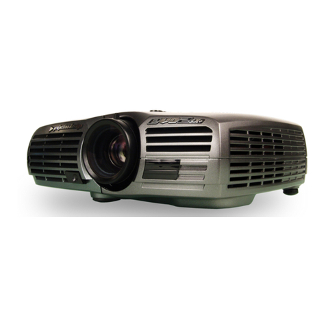
Sony VPL-FHZ55 User manual

DATA PROJECTOR
VPL-FHZ55
VPL-F420HZ
REMOTE COMMANDER
RM-PJ19
SERVICE MANUAL
1st Edition (Revised 1)

VPL-FHZ55
!警告
このマニュアルは,サービス専用です。
お客様が,このマニュアルに記載された設置や保守,点検,修理などを行うと感電や火災,
人身事故につながることがあります。
危険をさけるため,サービストレーニングを受けた技術者のみご使用ください。
!WARNING
This manual is intended for qualified service personnel only.
To reduce the risk of electric shock, fire or injury, do not perform any servicing other than that
contained in the operating instructions unless you are qualified to do so. Refer all servicing to
qualified service personnel.
!WARNUNG
Die Anleitung ist nur für qualifiziertes Fachpersonal bestimmt.
Alle Wartungsarbeiten dürfen nur von qualifiziertem Fachpersonal ausgeführt werden. Um die
Gefahr eines elektrischen Schlages, Feuergefahr und Verletzungen zu vermeiden, sind bei
Wartungsarbeiten strikt die Angaben in der Anleitung zu befolgen. Andere als die angegeben
Wartungsarbeiten dürfen nur von Personen ausgeführt werden, die eine spezielle Befähigung
dazu besitzen.
!AVERTISSEMENT
Ce manual est destiné uniquement aux personnes compétentes en charge de l’entretien. Afin
de réduire les risques de décharge électrique, d’incendie ou de blessure n’effectuer que les
réparations indiquées dans le mode d’emploi à moins d’être qualifié pour en effectuer d’autres.
Pour toute réparation faire appel à une personne compétente uniquement.
警告
万一,異常が起きた際に,お客様が電源を切ることが
できるように,設置の際には,機器近くの固定配線内
に専用遮断装置を設けるか,機器使用中に,容易に抜
き差しできるコンセントに電源プラグを接続してくだ
さい。
WARNING
When installing the unit, incorporate a readily accessible
disconnect device in the fixed wiring, or connect the
power cord to a socket-outlet which must be provided
near the unit and easily accessible, so that the user can
turn off the power in case a fault should occur.
WARNUNG
Beim Einbau des Geräts ist daher im Festkabel
ein leicht zugänglicher Unterbrecher einzufügen,
oder das Netzkabel mußmit einer in der Nähe
des Geräts befindlichen, leicht zugänglichen
Wandsteckdose verbunden werden, damit sich bei
einer Funktionsstörung die Stromversorgung zum Gerät
jederzeit unterbrechen läßt.
安全のために,周辺機器を接続する際は,過大電圧を持
つ可能性があるコネクターを以下のポートに接続しない
でください。
: LAN コネクター
上記のポートについては本書の指示に従ってください。
For safety, do not connect the connector for periph-
eral device wiring that might have excessive volt-
age to the following port.
: LAN connector
Follow the instructions for the above port.
VPL-FHZ55
For kundene i Norge
Dette utstyret kan kobles til et IT-strømfordelingssystem.

VPL-FHZ55 1 (P)
CAUTION
Use of controls or adjustments or performance
of procedures other than those specified herein
may result in hazardous radiation exposure.
注意
ここで指定した以外の手順で管理や調整,ある
いは操作を行うと,危険なレーザ放射に晒され
る場合があります。
GEFAHR
Bei geöffnetem Laufwerk und beschädigter oder
deaktivierter Verriegelung tritt ein unsichtbarer
Laserstrahl aus. Direkter Kontakt mit dem
Laserstrahl ist unbedingt zu vermeiden.
The WARNING label is located on the Top panel.
This Data Projector is classified as a CLASS 2 LASER
PRODUCT.
The CLASS 2 LASER PRODUCT label is located on the
right sideBase unit.
警告ラベルは上部パネルに貼られています。
本機は,CLASS2LASERPRODUCT に分類されます。CLASS
2LASERPRODUCT ラベルは,本機右側面のベースユニット
に貼られています。
Denna etikett är placerad på dataprojektorns övre panel.
Denna dataprojektor är klassificerad som en
LASERPRODUKT AV KLASS 2.
Etiketten LASERPRODUKT AV KLASS 2 finns på
dataprojektorns högra sida.

VPL-FHZ55
CAUTION
Danger of explosion if battery is incorrectly replaced.
Replace only with the same or equivalent type rec-
ommended by the manufacturer.
When you dispose of the battery, you must obey the
law in the relative area or country.
ATTENTION
Il y a danger d’explosion s’il y a remplacement incor-
rect de la batterie. Remplacer uniquement avec
une batterie du même type ou d’un type équivalent
recommandé par le constructeur.
Lorsque vous mettez la batterie au rebut, vous devez
respecter la législation en vigueur dans le pays ou la
région où vous vous trouvez.
VORSICHT
Explosionsgefahr bei Verwendung falscher Batterien.
Batterien nur durch den vom Hersteller empfohlenen
oder einen gleichwertigen Typ ersetzen.
Wenn Sie die Batterie entsorgen, müssen Sie die
Gesetze der jeweiligen Region und des jeweiligen
Landes befolgen.
FÖRSIKTIGHET!
Fara för explosion vid felaktigt placerat batteri.
Byt endast mot samma eller likvärdig typ av batteri,
enligt tillverkarens rekommendationer.
När du kasserar batteriet ska du följa rådande lagar
för regionen eller landet.
PAS PÅ
Fare for eksplosion, hvis batteriet ikke udskiftes
korrekt.
Udskift kun med et batteri af samme eller tilsvarende
type, som er anbefalet af fabrikanten.
Når du bortskaffer batteriet, skal du følge
lovgivningen i det pågældende område eller land.
HUOMIO
Räjähdysvaara, jos akku vaihdetaan virheellisesti.
Vaihda vain samanlaiseen tai vastaavantyyppiseen,
valmistajan suosittelemaan akkuun.
Noudata akun hävittämisessä oman maasi tai
alueesi lakeja.
FORSIKTIG
Eksplosjonsfare hvis feil type batteri settes i.
Bytt ut kun med samme type eller tilsvarende
anbefalt av produsenten.
Kasser batteriet i henhold til gjeldende avfallsregler.
注意
指定以外の電池に交換すると,破裂する危険があります。
必ず指定の電池に交換してください。
使用済みの電池は,国または地域の法令に従って
処理してください。
注意
注意
如果更换的电池不正确,就会有爆炸的危险。
只更换同一类型或制造商推荐的电池型号。
处理电池时,必须遵守相关地区或国家的法律。
2 (P)

1 (E)
VPL-FHZ55
Table of Contents
1-5. Optional Fixtures.....................................................1-34 (E)
1-5-1. Extension Boards and Extension Cables .......1-34 (E)
1-5-2. Connection.....................................................1-35 (E)
1-6. Precaution for Transporting.....................................1-37 (E)
1-7. Procedure When IR Receiver Reduced
Sensitivity................................................................1-38 (E)
1-7-1. Tools...............................................................1-38 (E)
1-7-2. Procedure .......................................................1-38 (E)
1-7-3. Procedure after Installing...............................1-38 (E)
1-8. Service Mode (Network Volume)............................ 1-39 (E)
1-8-1. Outline ...........................................................1-39 (E)
1-8-2. Update Function............................................. 1-39 (E)
1-8-3. Event Trace Function ..................................... 1-42 (E)
1-8-4. Setup Function ............................................... 1-45 (E)
1-9. Web Password Change ............................................ 1-46 (E)
1-10. Label Position.......................................................... 1-46 (E)
1-11. Indicator Display.....................................................1-47 (E)
1-12. Lead-free Solder......................................................1-48 (E)
2. Adjustments
2-1. Notes on Servicing ....................................................2-1 (E)
2-1-1. When the Optics Unit Assembly LEO or
Prism Block Assembly is Replaced .................2-1 (E)
2-1-2. When Replacing the C Board ..........................2-1 (E)
2-1-3. Parts That Require Adjustment of Laser
Luminance and Luminance Sensor When
They are Replaced ...........................................2-1 (E)
2-2. Preparation for Electrical Adjustment.......................2-2 (E)
2-2-1. Required Equipment ........................................2-2 (E)
2-2-2. How to Enter the Service Mode....................... 2-2 (E)
2-2-3. How to Enter the Model Name Display
(Shop Demonstration) Mode ...........................2-2 (E)
2-3. V COM Adjustment ..................................................2-3 (E)
2-4. Adjustment of Laser Luminance and Luminance
Sensor........................................................................2-3 (E)
2-4-1. Required Equipment ........................................2-3 (E)
2-4-2. Setting of This Unit and Power Meter
Sensor ..............................................................2-4 (E)
2-4-3. Preparation.......................................................2-5 (E)
2-4-4. Electronic Volume Adjustment ........................2-6 (E)
2-4-5. Luminance Dynamic range Adjustment ..........2-7 (E)
2-4-6. Luminance Constant Mode Adjustment ..........2-7 (E)
Manual Structure
Purpose of this manual............................................................ 3 (E)
Related manuals...................................................................... 3 (E)
Trademarks.............................................................................. 3 (E)
1. Service Overview
1-1. Precautions for Service Personnel.............................1-1 (E)
1-2. Appearance Figure/Board Locations......................... 1-1 (E)
1-3. Tighten Torque ..........................................................1-2 (E)
1-4. Disassembly ..............................................................1-2 (E)
1-4-1. Lens Cover Assembly ......................................1-6 (E)
1-4-2. Filter Cover Assembly .....................................1-7 (E)
1-4-3. Top Panel Assembly and H Board ...................1-8 (E)
1-4-4. C Board............................................................1-9 (E)
1-4-5. DC Fan (For Exhaust).................................... 1-11 (E)
1-4-6. Laser Unit Assembly LEO.............................1-12 (E)
1-4-7. Optics Unit Assembly LEO ...........................1-14 (E)
1-4-8. GC Board, DC Fan (For Wheel),
and OPT-UNIT Base (A)/(B)......................... 1-15 (E)
1-4-9. Gear Block ..................................................... 1-16 (E)
1-4-10. Power Unit ..................................................... 1-17 (E)
1-4-11. DC Fan (For Power Unit) .............................. 1-18 (E)
1-4-12. DC Fan (For Switching Regulator
(LD Power))...................................................1-19 (E)
1-4-13. Switching Regulator (LD Power) ..................1-20 (E)
1-4-14. GB Board ....................................................... 1-21 (E)
1-4-15. QD Board.......................................................1-22 (E)
1-4-16. DC Fan (Panel R/B and Panel G
(For Intake))...................................................1-23 (E)
1-4-17. QA Board .......................................................1-24 (E)
1-4-18. QB Board and QC Board...............................1-25 (E)
1-4-19. V Board..........................................................1-26 (E)
1-4-20. NF Board .......................................................1-26 (E)
1-4-21. U Board..........................................................1-27 (E)
1-4-22. In-polarizer (R)/(G)/(B) Assembly ................ 1-28 (E)
1-4-23. PS Assembly (P/S Converter)........................ 1-29 (E)
1-4-24. Shift and Prism Block Assembly ...................1-30 (E)
1-4-25. Out-polarizer (R)/(G)/(B) Assembly and
Out-pre-polarizer (R)/(G)/(B) Assembly .......1-31 (E)
1-4-26. SA Board and SB Board ................................1-32 (E)
1-4-27. Lens................................................................ 1-33 (E)
2 (E) VPL-FHZ55
5. Schematic Diagrams
C ...................................................................................... 5-2
GB ................................................................................. 5-23
GC ................................................................................. 5-25
H .................................................................................... 5-26
NF.................................................................................. 5-27
QA ................................................................................. 5-28
QB ................................................................................. 5-33
QC ................................................................................. 5-34
QD ................................................................................. 5-35
U .................................................................................... 5-36
V .................................................................................... 5-36
Frame Wiring................................................................. 5-37
6. Board Layouts
C ...................................................................................... 6-2
GB ................................................................................... 6-4
GC ................................................................................... 6-4
H ...................................................................................... 6-4
NF.................................................................................... 6-4
QA ................................................................................... 6-5
QB ................................................................................... 6-5
QC ................................................................................... 6-6
QD ................................................................................... 6-6
U ...................................................................................... 6-6
V ...................................................................................... 6-6
2-4-7. Luminance Sensor Adjustment ........................2-7 (E)
2-4-8. Device Save, Adjustment Items Check and
ALL Reset .......................................................2-8 (E)
2-4-9. Removal of Tools.............................................2-9 (E)
2-5. Software Update........................................................2-9 (E)
2-5-1. Preparation.......................................................2-9 (E)
2-5-2. Main (Scan Converter)................................... 2-11 (E)
2-5-3. Sub .................................................................2-12 (E)
2-5-4. Ext (Network) ................................................2-13 (E)
2-5-5. Ext (Network) Reset ......................................2-14 (E)
2-6. Quick Access2.........................................................2-15 (E)
2-6-1. Preparation.....................................................2-15 (E)
2-6-2. Saving of C Board/Opt Unit/3DGamma/
LookUpTable/Chiral/GCFB Data ..................2-15 (E)
2-6-3. Saving of DDC Data......................................2-16 (E)
2-6-4. Saving of NVM Data ..................................... 2-17 (E)
2-6-5. Writing of C Board/Opt Unit/3DGamma/
LookUpTable/Chiral/GCFB Data ..................2-18 (E)
2-6-6. Writing of DDC Data.....................................2-19 (E)
2-6-7. Writing of NVM Data.................................... 2-20 (E)
2-7. Adjustment Item Initialize Data .............................. 2-21 (E)
3. Spare Parts
3-1. Notes on Repair Parts...................................................... 3-1
3-2. Exploded Views............................................................... 3-2
3-3. Electrical Parts List .......................................................3-16
3-4. Packing Materials & Supplied Accessories................... 3-50
4. Block Diagrams
Overall............................................................................. 4-2

3 (E)
VPL-FHZ55
Manual Structure
Purpose of this manual
This manual is the Service Manual of the Data Projector VPL-FHZ55/F420HZ.
This manual contains the service overview, adjustments, spare parts, block diagrams,
schematic diagrams and board layouts.
The service of the SA and SB boards on this unit are basically performed by the
replacement of board.
Therefore, the schematic diagrams, board layouts and electrical parts list of the SA
and SB boards are not contained.
It is required to replace the LA and LB boards as a laser unit assembly LEO because
they cannot be replaced as an individual mount board or a mount part. Therefore, the
schematic diagrams, board layouts and electrical parts list of the LA and LB boards
are not contained.
Related manuals
In addition to this Service Manual, the following manuals are provided.
.Operating Instructions (supplied with unit)
This manual is necessary for application and operation of this unit.
.Protocol Manual (available on request)
This manual describes the protocol for controlling this unit.
Trademarks
Trademarks and registered trademarks used in this manual are as follows.
.Internet Explorer is a registered trademarks of Microsoft Corporation in the United
States and Other countries.
Other system names, product names, and company names appearing in this manual
are trademarks or registered trademarks of their respective holders.


1-1 (E)
VPL-FHZ55
1-1. Precautions for Service Personnel
.The laser diode is used as a light source of this unit.
Never allow the light source to emit light with the cabinet removed.
Otherwise, it may cause damage to eyes or skin.
.Do not remove the lens when the set is lighting.
Otherwise, it may cause damage to eyes or skin.
.Do not release the protection switch with the cabinet removed.
Otherwise, the light source may suddenly start emitting light, causing damage to eyes or skin.
.In order to avoid inappropriate use of the laser diode, do not disassemble the laser unit assembly LEO.
1-2. Appearance Figure/Board Locations
Appearance Figure
Board Locations
Section 1
Service Overview
H board
NF board
QB board
QC board
QA board V board
Power unit
Switching
regulator
(LD power)
C board
U board
GB board
GC board
SA board
QD board
SB board

1-2 (E) VPL-FHZ55
1-3. Tighten Torque
Tighten the each screw with the torque below.
n
When using the torque driver with the notation of cN.m, interpret it as follows.
Example: 0.8 N.m = 80 cN.m
.B2 x5: 0.19 ?0.03 N.m (1.94 ?0.31 kgf.cm)
.B3 x6: 0.53+0.07
_0.06 N.m (5.40+0.71
_0.61 kgf.cm)
.B3 x16: 0.80 ?0.12 N.m (8.16 ?1.22 kgf.cm)
.BVTP3 x8: 0.53+0.07
_0.06 N.m (5.40+0.71
_0.61 kgf.cm)
.BVTP3 x10: 0.70 ?0.10 N.m (7.14 ?1.02 kgf.cm)
.BVTP3 x12: 0.80 ?0.12 N.m (8.16 ?1.22 kgf.cm)
.BVTP3 x16: 0.80 ?0.12 N.m (8.16 ?1.22 kgf.cm)
.K3 x6: 0.80 ?0.12 N.m (8.16 ?1.22 kgf.cm)
.PSW3 x8: 0.80 ?0.12 N.m (8.16 ?1.22 kgf.cm)
.PSW3 x70: 0.80 ?0.12 N.m (8.16 ?1.22 kgf.cm)
.PSW4 x8: 1.4 ?0.2 N.m (14.0 ?2.0 kgf.cm)
.PSW5 x8: 1.4 ?0.2 N.m (14.0 ?2.0 kgf.cm)
.PWH3 x10: 0.80 ?0.12 N.m (8.16 ?1.22 kgf.cm)
.Step screw: 0.53
+0.07
_0.06 N.m (5.40+0.71
_0.61 kgf.cm)
.Screw (M3) (with stopper): 0.80 ?0.12 N.m (8.16 ?1.22 kgf.cm)
.Lens fixing screw (with stopper): 0.70 ?0.10 N.m (7.14 ?1.02 kgf.cm)
.Screw (with stopper): 0.70 ?0.10 N.m (7.14 ?1.02 kgf.cm)
.Connector screw: 0.53
+0.07
_0.06 N.m (5.40+0.71
_0.61 kgf.cm)
1-4. Disassembly
n
.The laser diode is used as a light source of this unit.
Never allow the light source to emit light with the cabinet removed.
Otherwise, it may cause damage to eyes or skin.
.Do not remove the lens when the set is lighting.
Otherwise, it may cause damage to eyes or skin.
.Do not release the protection switch with the cabinet removed.
Otherwise, the light source may suddenly start emitting light, causing damage to eyes or skin.
.In order to avoid inappropriate use of the laser diode, do not disassemble the laser unit assembly LEO.
t
Remove parts in the order of numbers shown in the figure, in this section.

1-3 (E)
VPL-FHZ55
1-4-6. Laser Unit Assembly LEO1-4-4. C Board 1-4-5. DC Fan (For Exhaust)
1-4-3. Top Panel Assembly and H Board
1-4-1. Lens Cover Assembly 1-4-27. Lens 1-4-14. GB Board
1-4-2. Filter Cover Assembly 1-4-20. NF Board

1-4 (E) VPL-FHZ55
1-4-15. QD Board 1-4-8. GC Board, DC Fan (For Wheel), and
OPT-UNIT Base (A)/(B)
1-4-7. Optics Unit Assembly LEO
1-4-16. DC Fan
(Panel R/B and Panel G (For
Intake))
1-4-10. Power Unit
1-4-13. Switching Regulator
(LD Power)
1-4-12. DC Fan
(Switching Regulator (For
Power))
1-4-11. DC Fan (For Power Unit)
1-4-9. Gear Block

1-5 (E)
VPL-FHZ55
1-4-17. QA Board 1-4-18. QB Board and QC Board
1-4-19. V Board 1-4-24. Shift and Prism Block Assembly
1-4-22. In-polarizer (R)/(G)/(B) Assembly
1-4-21. U Board 1-4-25. Out-polarizer (R)/(G)/(B) Assembly
and Out-pre-polarizer (R)/(G)/(B)
Assembly
1-4-23. PS Assembly (P/S Converter)
1-4-26. SA Board and SB Board

1-6 (E) VPL-FHZ55
1-4-1. Lens Cover Assembly
2Lens cover assembly
1Loosen the two screws with stopper (M3).
Three convex portions of lens cover assembly
n
When attaching the lens cover assembly, securely insert the three
convex portions of the lens cover assembly into the three grooves
of the top panel assembly.
Three grooves of top panel assembly

1-7 (E)
VPL-FHZ55
1-4-2. Filter Cover Assembly
1Loosen the screw with
stopper (M3).
2Two hooks
3Nylon rivet
4Sheet (RP)
5Filter cover assembly
n
When attaching the filter cover assembly, securely insert
the two hooks into the two holes of the top panel assembly.
Two holes of top panel
assembly

1-8 (E) VPL-FHZ55
1-4-3. Top Panel Assembly and H Board
1Two screws
(PSW3 x70)
4Top panel assembly
2Seven screws
(BVTP3 x12)
6LE sheet (top)
White model only
5Sheet (RP)
8Caution label
7Emblem
!= H board
!/ Nylon rivet
![ Button (H)
!\ Button (ARROW)
3Harness
n
Lift up the top panel assembly
slightly, then disconnect the
harness from the connector (CN11)
on the H board.
!- Holder (H)
!] Shield (H)
!; Cushion (ARROW)
CN11
9Cushion (rear)

1-9 (E)
VPL-FHZ55
1-4-4. C Board
n
When replacing the C board, perform the procedure before and after replacement.
(Refer to Section 2-1-2.)
C board (side A)
Connector connections (CN1601, CN1701, CN1801)
Pull this
portion.
CN1701
CN1601
CN1801
GC and SA
board
LA and LB
boards
U board
CN102 CN101
V board
QC board
QD board
GB board
QA boardQA board
CN208
CN207
CN104
CN303
CN202
CN201
Switching regulator (LD power)
H board
NF board
SB board
Power unit
Prism assembly
(R)
Prism assembly
(G)
Prism assembly (B)
CN103
CN205
CN304
CN302
CN105
CN204
CN301
CN106
Fuse connector assembly of laser unit assembly LEO
Thermistor of in-polarizer (B) assembly
Flexible flat cable
C board
1
2
3

1-10 (E) VPL-FHZ55
1Five harnesses
4Eleven screws
(PSW3 x8)
6Sheet (IC)
n
When replacing the
sheet (IC), attach it to
IC300 on the C board
with the silver side
facing up.
7Three flexible flat cables
9C board
8Two connectors
(B to B)
IC300
2Five harnesses
5LE shield (CT)
3Four harnesses

1-11 (E)
VPL-FHZ55
1-4-5. DC Fan (For Exhaust)
n
When attaching the DC fans, place them with the label side facing the direction as shown in the illustra-
tion.
3Cushion (EX)
4Relay connector
5Relay connector
6Wire saddle
Hooks of fan holder (EX)
Guide hooks
8Fan holder (EX)
!/ DC fan
9DC fan
Label side
Label side
5Wire saddle
6Wire saddle Harness
CN2604 GB boardCN2603DC fan DC fan
4Relay connector
Guide hookGuide hook
Harness
7Three screws
(BVTP3 x12)
Hole
1Screw
(PSW3 x8) 2Sheet (EX)
Hooks of fan holder (EX) Hooks of fan holder (EX)

1-12 (E) VPL-FHZ55
1-4-6. Laser Unit Assembly LEO
n
.Never disassemble the laser unit assembly LEO.
.When replacing the laser unit assembly LEO, perform the procedure after replacement.
(Refer to Section 2-1-3.)
5Three screws
(PSW3 x8)
3Relay connector
1Flexible flat cable
7Laser unit assembly LEO
7Laser unit assembly
LEO
6Hold the two portions of the laser
unit assembly LEO on both sides
and lift it up in the direction of the arrow.
n
Be careful not to give a shock to the
laser unit assembly LEO.
n
When removing and installing the laser unit
assembly LEO, be careful not to touch the heat
sink, wheel and lens portions.
Bottom side
GC board
4Relay connector
CN2803
2Wire saddle
Other manuals for VPL-FHZ55
7
This manual suits for next models
1
Table of contents
Other Sony Projector manuals

Sony
Sony SRX-R220 User manual

Sony
Sony VPL-PX20 User manual

Sony
Sony VPL-VW590ES Service manual

Sony
Sony Supersmart VPL-PX15 User manual

Sony
Sony MP-CL1A User guide

Sony
Sony HDMI VPL-FE40L User manual

Sony
Sony VPL-GTZ280 User manual

Sony
Sony VPL-VW95ES User manual

Sony
Sony HDMI VPL-EW7 Service manual

Sony
Sony VPL-HW40ES User manual

Sony
Sony MP-CL1 User guide

Sony
Sony Cineza VPL-HS2 User manual

Sony
Sony VPL-FX51 User manual

Sony
Sony VPL-VW890ES Service manual

Sony
Sony VPL-ES1 User manual

Sony
Sony VPL-VW550ES User manual

Sony
Sony VPL-SW535 User manual

Sony
Sony VPL-SW125 User manual

Sony
Sony VPL-VZ1000 Service manual

Sony
Sony VPL-BW7 User manual