-OWNER’S
RECORD
The
model
and
serial
numbers
are
located
at
the
rear.
Record
these
numbers
in
the
space
provided
below.
Refer
to
them
whenever
you
call
upon
your
Sony
dealer
regarding
this
product.
Model
No.
WARNING
To
prevent
fire
or
shock
hazard,
do
not
ex-
pose
the
unit
to
rain
or
moisture.
Serial
No.
RISK
OF
ELECTRIC
SHOCK
OC
NOT
OPEN
CAUTION:
TO
REDUCE
THE
RISK
OF
ELECTRIC
SHOCK,
DO
NOT
REMOVE
COVER
(OR
BACK)
NO
USER-SERVICEABLE
PARTS
INSIDE
REFER
SERVICING
TO
QUALIFIED
SERVICE
PERSONNEL.
JN
/\
This
symbol
is
intended
to
alert
the
user
to
the
presence
of
uninsulated
“dangerous
voltage”
within
the
prod-
uct’s
enclosure
that
may
be
of
suffi-
cient
magnitude
to-constitute
a
risk
of
electric
shock
to
persons.
This
symbol
is
intended
to
alert
the
user
to
the
presence
of
important
operating
and
maintenance
(servicing)
instructions
in
the
literature
accompa-
nying
the
appliance.
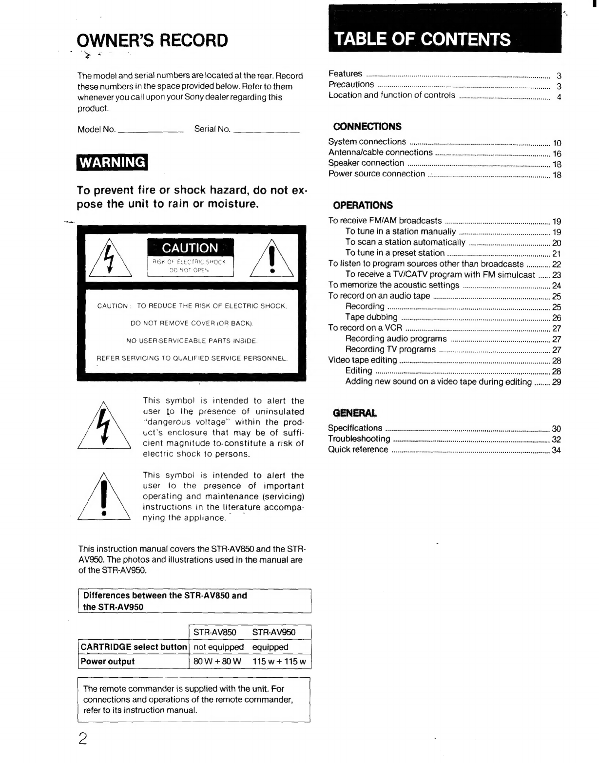
This
instruction
manual
covers
the
STR-AV850
and
the
STR-
AV950.
The
photos
and
illustrations
used
in
the
manual
are
of
the
STR-AV950.
[
Differences
between
the
STR-AV850
and
the
STR-AV950
STR-AV850
STR-AV950
CARTRIDGE
select
button]
not
equipped
equipped
Power
output
80W+80W
115w+115
Ww
The
remote
commander
is
supplied
with
the
unit.
For
connections
and
operations
of
the
remote
commander,
refer
to
its
instruction
manual.
Z
TABLE
OF
CONTENTS
FOAtUITeS
ooecccs
ke
cetter
a
hhreciely
ba
3
Precautions
3
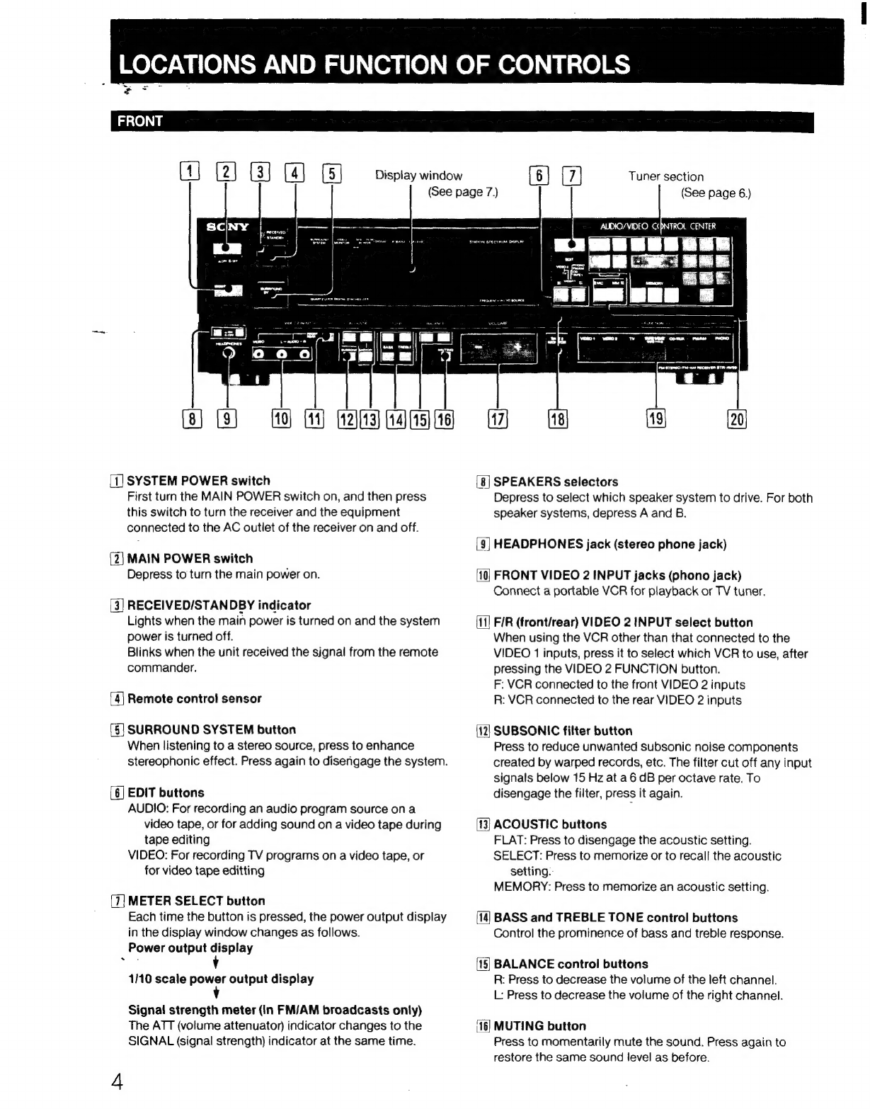
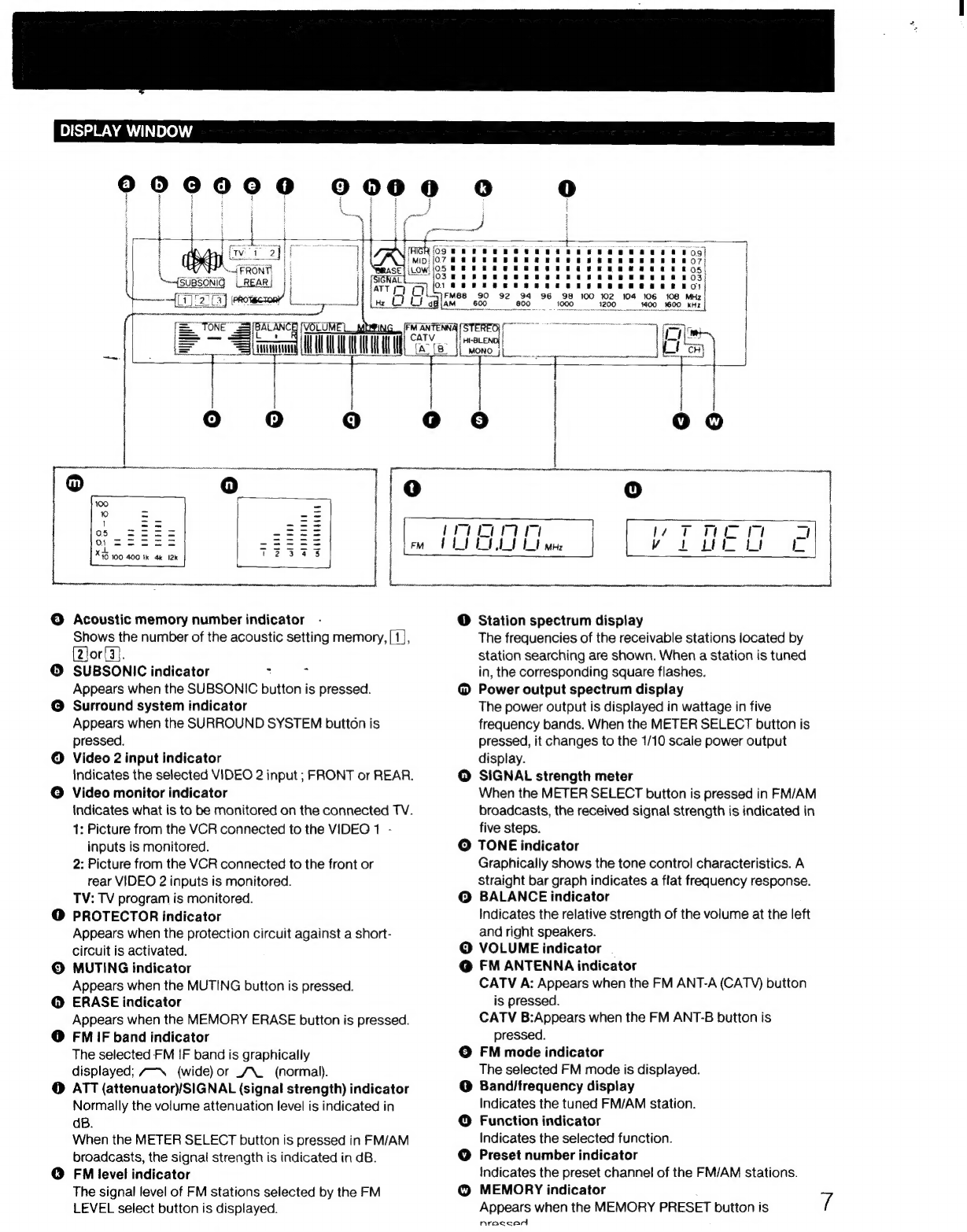
Location
and
function
of
controls
4
CONNECTIONS
SYSTEM
CONNECTIONS
oe
eceecesessseesssssessccneesseseeseeseconsstenestersecarsenacs
10
Antennalcable
CONNECtIONS
......e..cccccccssssstessesecctssessecesssesscsssssseees
16
SPEAKES
CONNECTION
oe.
eecescesessecssesssesssessessseesceesesesetesestcsssesnsesraseas
18
POWE?
SOUFCE
CONNECEHION
.oi...eesccceecessecctsssessecsseesesesessesuceeeseenecetesess
18
OPERATIONS
To
receive
FM/AM
broadcasts
.............
To
tune
in
a
station
manually
To
scan
a
station
automatically
To
tune
in
a
preset
Station
oo.
ececcsssecseecsesessescoesnsennees
To
listen
to
program
sources
other
than
broadcasts
............
22
To
receive
a
TV/ICATV
program
with
FM
simulcast
......
23
To
memorize
the
acoustic
SettiNGS
cece
essessteseseseeeees
24
TO
reCOFd
ON
AN
AUGIO
TAP!
ones
eeeeccecscssessesssscecseesucsseaecsesenssensess
25
RECOLING
2.
i
scsinsea,
BankihotinentanakeGekenSareantengs,
25
PAPO
GUDDIING
esc.
csstccecceccctiscsoseessssicacnstevaewsatsseansasenccdeassiautariaass
26
TOECOrd
ON.
AVGR
gives
cote
esecehasslecaustsccensleaieicacvaisiaa
nance,
27
Recording
audio
programs
.......ccccesecsee
Recording
TV
programs
Video
tape
OditING
on.
ec
eescsesntesseecssssnesseessscsseessesesessesteessesseeses
28
EGUtING
satiate
tetas
cradetec
aa
Neiceatiecs
deine
sesaivatcisinnecdioad
28
Adding
new
sound
on
a
video
tape
during
editing
........
29
GENERAL
SPe@CifiCATIONS
oon.
ee
eceesesssecsescesseeseessesstesersstesessesseseese
Troubleshooting
Quick
reference