manuals.online logo
Brands
  1. Home
  2. •
  3. Brands
  4. •
  5. Sony
  6. •
  7. Stereo Receiver
  8. •
  9. Sony STR-DE185 User manual

Sony STR-DE185 User manual

Other manuals for STR-DE185

5

Other Sony Stereo Receiver manuals

Sony STR-DE835 User manual

Sony

Sony STR-DE835 User manual

Sony STR-DA4ES - Fm Stereo/fm-am Receiver User manual

Sony

Sony STR-DA4ES - Fm Stereo/fm-am Receiver User manual

Sony XAV-AX8150 User manual

Sony

Sony XAV-AX8150 User manual

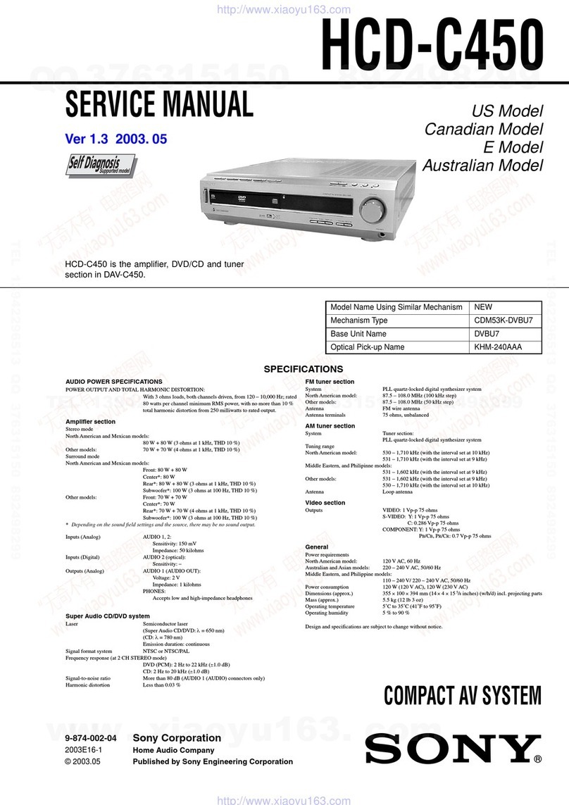
Sony STR-DE845 User manual

Sony

Sony STR-DE845 User manual

Sony STR-DE335 - Fm Stereo/fm-am Receiver User manual

Sony

Sony STR-DE335 - Fm Stereo/fm-am Receiver User manual

Sony STR-DE135 User manual

Sony

Sony STR-DE135 User manual

Sony XAV-AX5500OB User manual

Sony

Sony XAV-AX5500OB User manual

Sony STR-DG300 User manual

Sony

Sony STR-DG300 User manual

Sony CFS-W500S User manual

Sony

Sony CFS-W500S User manual

Sony XAV-AX6000 User manual

Sony

Sony XAV-AX6000 User manual

Sony STR-DE225 User manual

Sony

Sony STR-DE225 User manual

Sony STR-DH830 Setup guide

Sony

Sony STR-DH830 Setup guide

Sony STR-DE998 - A/v Receiver User manual

Sony

Sony STR-DE998 - A/v Receiver User manual

Sony STR-DE695 - Fm Stereo/fm-am Receiver User manual

Sony

Sony STR-DE695 - Fm Stereo/fm-am Receiver User manual

Sony STR-DB2000 User manual

Sony

Sony STR-DB2000 User manual

Sony STR-KS500 User manual

Sony

Sony STR-KS500 User manual

Sony STR-K670P  (HT-DDW670) User manual

Sony

Sony STR-K670P (HT-DDW670) User manual

Sony STR-DA7ES - Fm Stereo/fm-am Receiver User manual

Sony

Sony STR-DA7ES - Fm Stereo/fm-am Receiver User manual

Sony STR-GX6ESII User manual

Sony

Sony STR-GX6ESII User manual

Sony XAV-W600BT User manual

Sony

Sony XAV-W600BT User manual

Sony STR-DE597P User manual

Sony

Sony STR-DE597P User manual

Sony STR-DA4400ES User manual

Sony

Sony STR-DA4400ES User manual

Sony STR-DE485 User manual

Sony

Sony STR-DE485 User manual

Sony STR-DE695 - Fm Stereo/fm-am Receiver Quick start guide

Sony

Sony STR-DE695 - Fm Stereo/fm-am Receiver Quick start guide

Popular Stereo Receiver manuals by other brands

Teac AG-680 Service manual

Teac

Teac AG-680 Service manual

Kenwood KR-V888D instruction manual

Kenwood

Kenwood KR-V888D instruction manual

Teac AGV1050 owner's manual

Teac

Teac AGV1050 owner's manual

Pioneer Elite SC-68 Service manual

Pioneer

Pioneer Elite SC-68 Service manual

Pioneer SX-1250 operating instructions

Pioneer

Pioneer SX-1250 operating instructions

Marantz CINEMA 70S owner's manual

Marantz

Marantz CINEMA 70S owner's manual

Kenwood KMDX92 instruction manual

Kenwood

Kenwood KMDX92 instruction manual

Yamaha RX-830 owner's manual

Yamaha

Yamaha RX-830 owner's manual

Pioneer AVH-Z7250BT owner's manual

Pioneer

Pioneer AVH-Z7250BT owner's manual

Denon AVR-1311 owner's manual

Denon

Denon AVR-1311 owner's manual

Denon AVR-S760H owner's manual

Denon

Denon AVR-S760H owner's manual

Denon AVR-X7200W Service manual

Denon

Denon AVR-X7200W Service manual

Radio Shack DX-399 owner's manual

Radio Shack

Radio Shack DX-399 owner's manual

Pioneer SX-1000TA operating instructions

Pioneer

Pioneer SX-1000TA operating instructions

Yamaha MusicCast TSR-5B3D owner's manual

Yamaha

Yamaha MusicCast TSR-5B3D owner's manual

Sherwood Newcastle RX-770 operating instructions

Sherwood

Sherwood Newcastle RX-770 operating instructions

Panasonic AJSD955B - DVCPRO50 STUDIO DECK Brochure & specs

Panasonic

Panasonic AJSD955B - DVCPRO50 STUDIO DECK Brochure & specs

Pioneer SX-838 Service manual

Pioneer

Pioneer SX-838 Service manual

manuals.online logo
manuals.online logoBrands
  • About & Mission
  • Contact us
  • Privacy Policy
  • Terms and Conditions

Copyright 2025 Manuals.Online. All Rights Reserved.

FM Stereo
FM.AM Receiver
Operating Instructions
Owner's Record
The model and serial numbers are located on the vzar panel. Record the serial number
il! lbe space provided below. Refer 1o them wllenever you call upon your Sony dealer
regarding this product.
Model No. STR-DEi85 Serial No.
STR-DE185
© 2002 Sony Corporation
I!?1:II_]_II_[i]
To prevent fire or shock hazard, do not
expose the unit to rain or moisture.
To prevem fire, do not cover the ventilation of _he
apparatus with newspaper, table-cloths, curtains, etc.
And don't place lighted candles on the apparatus.
To prevent fin or shock hazard, do not place objects
filled with liquids, such as vases, on the apparatus.
Don't throw away the battery with
general house waste, dispose of it
correctly _s chemica_ waste.
Do not install tile appliance in a confined space, such
as a bookcase or built-in cabinet.
For customers in the United States
w_m_:_o m_me _s mx_ eJcm¢ mc_
D0.OTmm_
_,oUBm_EF_C_mJEm mm_.
This symbol is intended to ale(t the
user to the p_sence of uninsulated
"dangerous voltage" within the
product's enclosu_ that may be of
sufficient magnitude to constitute a
risk of electric shock to pe_ons.
This symbol is intended to alel"t the
user to the pl'esence of important
operating and maintenance (servicing)
instructions in the lileratu_
accompanying the appliance.
WARNING
This equipment has been tested and found to comply
with the limits for a Class B digital device, pursuant
to Part 15 of the FCC Rules. These limits are
designed to provide reasonable protection apair;st
harmful interference in a residential installation. This
equipmem generates, uses, and can radiate radio
frequency energy and, if not installed and used in
accordmlce with lhe instructions, may cause harmful
interlhl_nce to radio communications. However, there
is no guarmttee that imerference will not occur in a
particular installation. If this equipment does cause
harmful intel_ference to radio or television reception,
which can be deten_ined by turning the equipment
off and on, the user is encouraged to try to correct Ihe
imerthl_nce by one or more of the following
measures:
-Reoriem or relocate the receiving antenna.
Increase the separation between the equipment mid
receiver.
Coml_t the equipmem into an outlet on a circuit
different from thzt to which the receiver is
connected.
Consult the dealer or an experienced radiofFV
technician for help.
CAUTION
YOUarc cautioned that any chmtges or modification
not expressly approved in this manual could wild
your authority to operate this eq uipmem.
Note to CATV system installer:
This reminder is provided to cal! CATV system
installer's zttention to Article 820-40 of the NEC thzt
plx_vides guidelines for proper grounding and, in
particular, specifies that the cable ground shall be
connected to the grounding syslem of _he betiding, as
close to the point of cable enh2€ as practical.
ENERGY STAR <'°is a U.S. registered
mark.
As an ENERGY STAR a' partner, Sony
Corporation has detenlfined that flits
product meets the ENERGY STAR n
guidelines for energy efficiency.
2GB
Main unit ............................................... 5
Hooking Up the Components
Required cords ....................................... 6
Antenna hookups ................................... 7
Audio/Video component hookups ......... 8
Speaker syslem hookups ....................... 9
Other hookups ..................................... 11
Clearing the receiver's memory .......... 11
Basic Operations
Selecting the component ..................... 12
Adjusting the sound ............................. 12
Changing the display ........................... 12
Receiving Broadcasts
Storing FM stations automalically
(AUTOBETICAL)* ...................... 13
Direct tuning ........................................ 13
Automatic tuning ................................. 14
Preset tuning ........................................ 14
Using fhe Radio Data System
(RDS)* .......................................... 16
Other Operations
Naming preset stations and program
sources ........................................... 18
Recording ............................................ 18
Using 1he Sleep Timer ......................... 19
Additional Information
Precautions .......................................... 20
"I_oubleshooting ................................... 20
Specifications ...................................... 22
Remote button description ................... 24
Changing the factory setting of
a function button ........................... 27
* Models of area c_xle CEL, CEK onty.
3Ga
About This Manual
The hlslructions in this manual ale for mode!
STR-DE185. Check your mode! number by looking at
the lower right comer of the front panel. In this
manual, tile illustration for area code CEL is used for
i!luslration purposes unless stated otherwise.
About area codes
The area code of the receiver you pm_hased is
shown on _he lower portion of the rear panel (see
the illustration below).
_4-XXX-XXX-XX_
Area code
Any differences in operation, according to the
area code, ale clearly indicated in the rex{, for
example, "Models of area code AA only".
Note for the supplied remote
The DVD button on the remo_eis not available.
Inserting batteries into the
remote
Insert R6 (size-AA) bztteries with the +_nd -
properly oriented in the bt_ttery compartment,
When using the remole, point it _t the remote
sensor [] on the receiver.
¢
Tip
The ins{ructions ill this manual describe file controls
o11{he receiver. You can also use the controls on the
supplied remote if they have the same or similar
names as _hose on the receiver, For details on the use
of your remote, see pages 24-27.
Tip
Under normal conditions, tile ba{teries should ]as{ fi_r
about 6 months. When the remote no longer operales
_he receiver, replace all bat{eries with new ones.
Notes
•DO not leave _he remote in an extremely hot or
humid place.
• Do not use a new battery with an old one.
• Do not expose the remote sensor to direct sunlight
or lighting apparatuses. Doing so may cause a
malfunction.
• If you don't use the remote for an extended period
of {ime, remove the batteries to avoid lx_ssible
damage from bzttery leakage and corrosion.
4GB
Illustration number
How to use this page
Use this page to find the location of buttons that are NAME [] (18)
mentioned in the text. T T
Name of button/part Reference page
ALPHABETICAL ORDER
AM [_] (13, 14)
BALANCE L/R [_2{Jj(12)
BASS +/ [_] (!2)
BASS BOOST []2_](12)
CD [ii_)(8, 12)
DIRECT [_ (13)
DISPLAY I!i_](12, 16)
Display I_] (l 1-16, [g, 19)
ZM [_] (13, 14)
FM MODE [_] (14)
IR (receptor) [_] (4, 22)
MASTER VOLUME _{_](12, 20)
MD/FAPE {_ (8, 12)
MEMORY/ENTER [_] (13, 15,
]8)
MUTING _ (12, 20)
NAME [_] (18)
Numeric buttons [[_[](13)
PHONES [_ (12, 21)
PRES ET/PTY SELECT +/-
(models of area code CEL,
CEK) [_ (!5, 16)
PRESET TUNING +/- (models of
al_a code U) [_1 (15, 23)
PTY (models of area code CEL,
CEK) [_] (16)
SHIFT _1 (l 5)
SLEEP (models of area code U)
[_[] (19)
SPEAKERS A _[_ (10, 12)
SPEAKERS g [_[_](10, 12)
TREBLE +/- _Q}(12)
TUNER _i_](8, 12-15, 18)
TUNING/CHAR +/- [_] (14, 18)
VIDEO 1I][[_(12)
VIDEO 2 [{i_ (8, 12)
BUTTON DESCRIPTIONS ]
I/(_ (power) [[_[](11, 13, 23)
i!!!!!'!!!iZ
E
[] Audio cord (not supplied)
White (L) White (L)
Red (R) _ ' Red (R)
[] Speaker cords (not supplied)
Before you get started
•T_u'n off the power to all conlponents before naaki_lg any connections.
•DonotconnecttheACpower¢ordtMtiJalJoftheconnectionsareconlpleted.
•Be sure to make comlections firmly to avoid hum and noise.
•When connecting an audio cord, be sure to match the color-coded pi_s to the appropriate jacks on the
components: white (left, audio) to white; and red (right, audio) to red.
6GB
m
AM loop antenna
(supplied)
__ FM wire antenna*
(supplied)
BB
.e
o
o
€
o
3
0
0
The shape of the connector varies depending on the area code.
Notes on antenna hookups
•To prevent noise pickup, keep the AM loop
antenna away from the receiver and other
components.
• If you have poor AM reception, connect a
6to 15 meters (20 to 50 feet) insulated wire
(not supplied) to the AM antenna terminal in
addition to the AM loop antenna. Try to extend
the wire outdoors and keep it horizontal.
• Be sure to f_.dly extend the FM wire antenna.
• After connecting the FM wire antenna, keep it
as horizontal as possible.
7GB
m
_lnlllll
o&@
Video Component Hookups
VCR VCR
[]
OUT fN
CD player MD or Tape deck
Audio Component Hookups
Note on video component
hookups
Use the function buttons (VIDEO 2,
MD/I'APE, CD, TUNER) to select the
VIDEO 1 AUDIO OUT signal. You can record
this audio signal by connecting a recording
component such as a cassette deck (to the
VIDEO I AUDIO OUT jack).
8GB
Speaker A (R) Speaker A (L)
[] []
*,,
b&NCL4_B
Z
O
O
€
O
0
0
l0
[] []
l
Speaker B* Speaker B*
(R) (L)
* If you have an additional front speaker system, connect them to tile SPEAKERS B _erminals.
Tips
•Twist the stripped ends of the cords about 15 mm
(2/3 inch). Be sure to match the speaker cord to the
appropriate tel_ainal oll the components: + lo + and
-to -. If the cords ale reversed, the sound will be
distorted and will lack bass.
• To avoid damaging your speakers, make sure that
you turn down the volume before you [Ul_ off the
receivel\ When yott turn o1!the receiver, lhe volume
remains st the level you turn offthe receiver.
9GB
To avoid short-circuiting the
speakers
Short-circuiting of the speakers may damage
the receiver. To prevent this, make sure to take
the following precautions when connecting the
speakers.
Make sure the stripped ends of each
speaker cord does not touch another
speaker terminal, the stripped end of
another speaker cord or the metal parts
of the receiver.
Examples of poor conditions of the
speaker cord
Selecting the speaker system
To drive the speakers, select the speaker system
Its follows. The SPEAKERS indicator(s)
light(s) up.
To drive Press SPEAKERS button
Speaker System AA
(connected to lhe
SPEAKERS A
terminals)
Speaker System B B
(connected to lhe
SPEAKERS B
terminals)
Both speaker A and B
systems A and B
(parallel connection)
Tips
•Press SPEAKERS A or B bu_ton again _odeselect
the speakers.
• The default speaker system is Speaker System A.
Stripped speaker cord is touching another
speaker terminal.
Stripped cords are touching each other
due to excessive removal of insulation.
10c8