[]
n
n
[]
ll
ll
D
n
n
LJ
[J
n
LJ
D
r1
LJ
r1
L
LJ
[J
l]
u
u
L
,,
[TI
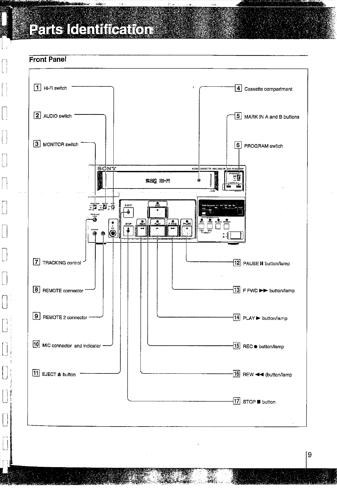
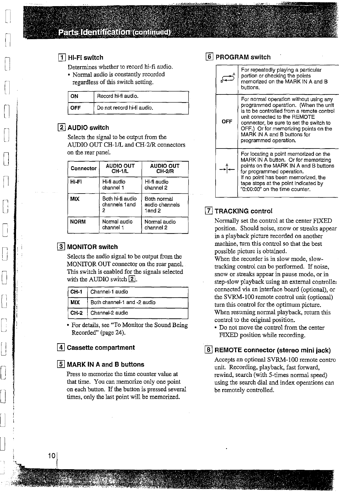
Hi-Fi switch
Determines whether
to
record hi-fi audio.
• Normal audio
is
constantly recorded
regardless
of
this switch setting,
ON
Record hi-Ii audio.
OFF
Do
not record hi-fi audio.
[I]
AUDIO switch
Selects the signal to
be
output from the
AUDIO OUT CH-1/L and CH-2/R connectors
on the rear
panel
Connector AUDIO OUT AUDIO OUT
CH-1/L CH-2/R
Hi-Fi Hi-Ii audio Hi-Ii audio
channel 1 channel2
MIX
Both
hi-Ii audio Both normal
channels 1and audio channels
2 1and 2
NORM Normal audio Normal audio
channel 1 channel 2
[!] MONITOR switch
Selects the audio signal to
be
output from the
MONITOR OUT connector on the rearpanel.
This switch is enabled for the signals selected
with the AUDIO switch[fil.
CH-1
Channel-1 audio
MIX Both channel-1 and -2 audio
CH-2 Channel-2 audio
•
For
details, see "To Monitor the SoundBeing
Recorded" (page 24).
[!] Cassette compartment
(ID
MARK IN A and B buttons
Press to memorize the time counter value
at
that time. You can memorize only one point
on each button. Ifthe button is pressed several
times, only the last point will be memorized.
I]] PROGRAM switch
For repeatedly playing a particular
A portion or checking
the
points
.o
memorized on the
MARK
IN
A and B
buttons,
For normal operation without using any
programmed operation. (When the unit
is to be controlled from a remote control
unit connected to
the
REMOTE
OFF connector,
be
sure to set the switch to
OFF.) Or
for
memorizing points on the
MARK
IN
A and B buttons for
programmed operation.
For locating a point memorized
on
the
MARK
IN
A button.
Or
for memorizing
A points on the MARK IN A and B buttons
-1-
for programmed operation,
If no point has been memorized, the
tape stops
at
the point indicated
by
"0:00:00" on the time counter.
[zJ
TRACKING control
Normally set the control
at
the center FIXED
position. Should noise,
snow
or
streaks appear
in
a playback picture recorded
on
another
machine,
tum
this control so that the best
possible picture is obtained.
When the recorder is in slow mode, slow-
tracking control can
be
performed.
If
noise,
snow
or
streaks appear
in
pause mode,
or
in
step-slow playback using an external controlle,
connected
via
an interface
board
(optional),
or
the SVRM-100 remote control unit (optional)
tum
this control for the
optimum
picture.
When
resuming normal playback, return this
control
to
the original position.
• Do not move the control from the center
FIXED position while recording.
I]] REMOTE connector (stereo mini jack}
Accepts
an
optional
SVRM-100
remote contra
unit. Recording, playback, fast forward,
rewind, search (with 5-times normal speed)
using the search dial and index operations can
be remotely controlled.