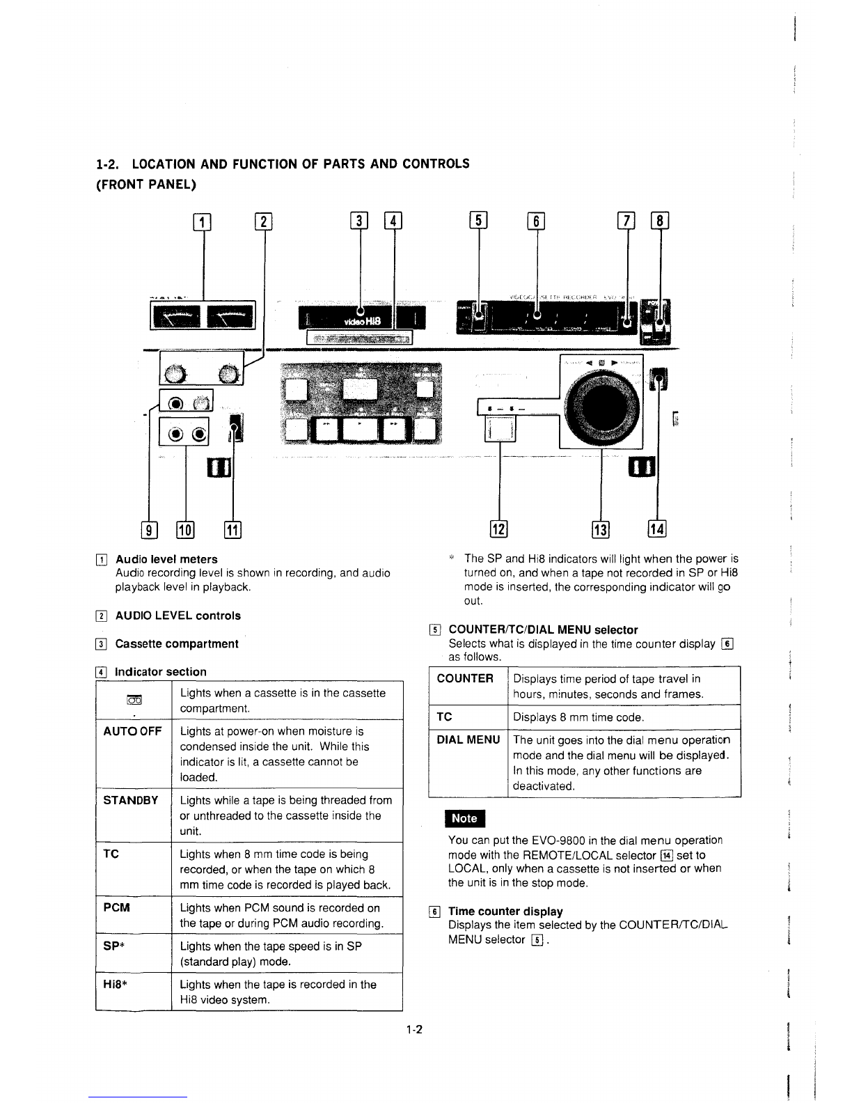
Sony EVO-9800 User manual

I-
li
図
i11111111111111111111111111111ljll
型竺雪
Z
4
臨港開
m
回
仁子一回・・
E
通~~・-_
11F
軍国
Fτ1
U
E
⑤⑤固L,;I..-Iー
i

SPECIFICATIONS
国竺旦
Recording system Rotary
2
・
head
helical scan
Luminance: FMrecording
Color signal: converted subcarrier direct
recording
Video signal system EIA standards, NTSCcolor
Audio recording system
也些豆
Normal recording
AFM: Rotary head, FMsystem
(monaural)
PCM: PCMformat (two channels)
Inputs VIDEOIN (BNCtype) x1
1.0 Vp‑p:t 0.3 Vp-p, 75 ohms,
unbalanced, sync negative
Outputs VIDEOOUT(BNCtype) x1
1.0 Vp‑p:t 0.2 Vp-p, 750hms,
unbalanced, sync negative
DUBOUT(7‑pin) x1
MONITORTV
(8
田
pin)
x1
MONITORVIDEO(BNCtype) x1
Horizontal resolution Hi8 moderecording: 400 lines (both B/W
and color)
S/N Hi8 mode
Morethan 45dB
Conventional format
More than 45dB(color)
Sync signal input SYNCIN (BNCtype) x1
Recording level control
出坐
2.5 Vp‑p (1 to 5Vp-p), 75 ohms,
unbalanced
Automatic
Input AUDIOLINE IN CH-1/L,
CH
・
2/R
(XLR 3‑pin
female) x1each
+4
dB
, 10 kohms, balanced
MICROPHONESCH-1/L,
CH
・
2/R
(phone
jack) x1each
‑60 dB. 3kohms. unbalanced
Outputs AUDIOLl NEOUT
CH
・
1/L
,
CH‑2/R (XLR
3
・
pin male) x1each
+4dBm(at 600 ohmload) , balanced
MONITORAUDIO (phono jack) x1
ー
5
dB(at 47 kohmload)
MONITORTV(8 pin) x1
HEADPHONES(stereo phonejack)
For 8‑ohm headphones
Level adjustable (from ‑26to ‑46 dB)
Frequency response AFM:30 to
15
,000 Hz:t 3dB
PCM:2010 15000 Hz
(bolh audio channel 1and 2)
Dynamic range PCM:more than 80 dB
Recording level control Manual or limiter selectable
PCMsampling frequency
31.5 kHz
lOtherfunctions
Pause
Search
Syncsystem
Astill picture is oblained with long pause
function
Still, 1/30 to 19 times normal speed in
forward direction; 1/30 to 17times
normal seed in reverse direction
Automatic swilching between internal and
external
Dropout compensator Buill‑in
│Tapetransport
Tape speed 14.3 mm/sec.
Recording and playback time
Approx. 120 minutes (in SPmode)
Fast forward and rewind time
Within 3minutes (with E6‑120/P6‑120)
Tape compatibility 8mmvideo cassette tapes
Usable tapes E6-HME, P6-HMP, P6‑MPseries and
equivalent
回型旦!
Power requirements Rated voltage: 100 ‑120 VAC, 50/60 Hz
Operating voltage: 90 ‑132 VAC
Powerconsumption 50 W
Operating position Horizontal (up to 20degrees)
Storage temperature ‑20o
Cto +60o
C(‑40Fto 1400F)
Operating temperature 5
0Cto 400C(41 0Fto 1040F)
Dimensions 424 x146.5 x452 mm
(w/h/d)
(16
3
/4X5'/8X17
ア 18
inches)
not including projecting parts and controls
Weight Approx. 14 kg (30 Ib 14 oz)
Supplied accessories ACpower cord (1)
Operating instructions (1)
Design and specifications are subject to change without notice.
IRecommendedvideo equipment and
accesso
巾
S
Editing Control Unit RM-450, RM‑440 (when the BKU‑703A installed)
Color Video Monitor SonyCVMand PVMseries
Color Video Camera Sony DXCseries
33P Editing Interface BKU‑703A
Remote Control Unit RM-500, RM‑580 (when the BKU‑703Ainstalled)
Cleaning Cassetle
V8
・
25CLH
Remote Control Cable RCC‑5G (9-pin), RCC‑5F (33‑pin)
Dubbing Cable VDC‑5 (5 m)
Monitor Connecting Cable VMC‑3P(3
m)
, VMC‑5P(5 m),
VMC‑10P(10 m)
Multi Remote Control Unit RM‑555 (when the BKU‑703A installed)
Video and Audio Switcher BVS‑500
VTRSelector RM‑V5
Rack Mount Kit RMM‑980

TABLEOFCONTENTS
1. GENERAL DISCRIPTION
1‑ 1. Features .----_,....----......…….....................1-1
1‑2. Location and Function of Parts
and Controls
・…・・・・・…..…・…・…・・…・・・…・・・・・・
1-2
1‑3. Notes on Video Cassette
…・・…・……・・・・・・…
1-9
1‑4.
Connections'"
………・・…・・…・・・・…・…・・・……
...1
・
10
1‑4‑ 1. Basic Connections
…・・…・・・…・…・・・・・・…
"'1-10
1‑4‑2. Connections of Headphones
and Microphones
....…・・・・・…・・・・・・…...…
1-11
1‑5. Editing
…..…・・・・・・・……………・・…・・…・・…・・・…
1-11
1‑6 Installation of BKU‑703A (33P)
Editing Interface
........……・・…・・…・・・・・・……
1-12
1‑7 Rack Mounting
.............…・・…………・・・…
...1
・
12
2. SERVICE INFORMATION
2‑ 1. Removal and Installation of the Cabinet "'2‑1
2‑2. Removal of the Mecha Deck Block
…・・…
'2-3
2
・
3.
Removal of the Cassette‑up Compartment
Assembly"
…・…...............・
H
・-…・…・・・・・・…・・・
2
・
3
2‑4. Removal of the Power Supply Block
..…・…
2-4
2‑5. Service of the Printed Circuit Boards
...…
2-4
2
ふ1.
Service the AU‑127 Board
...……・・…-…
2-4
2‑5‑2. Service the DC‑45 Board
………・・・……
...2
・
5
2‑5‑3. Opening the
VO
・
24
and YC‑39 Boards …
2-5
2‑5‑4. Opening the SY‑145 Board
……….....・
H
・
2-5
2
ふ
5.
Opening the MB‑19 and MD‑23 Boards 2‑5
2
・
5-6.
Opening the HK‑4 Board
.…・・……・・・……
2
・
6
2
ふ
7.
Opening the SE‑10 Board
………...・
H
・..…
2
・
6
2
ふ
8.
Removal of the RS‑31 Board
…・・・…
......2
・
7
2‑6 Function Control Panel Positioning
…・・…・…
2-8
2‑7. Location of Main Parts
…・・………-…・・・・…
'2-9
2
・
7
・1.
Location of the Main Mechanical
Parts/Components
…'"・
H
・-.…...・
H
・..……
2-9
2
・
7-2.
Location of the Printed Circuit
Boards
………...・
H
・..…………..-・
H
・..……
2-13
2‑8. Printed Circuit Boards
…………………・・...・
2-17
2‑9. Connectors
……......・
H
・..………….-.・
H
・_.……
2
・
17
2‑10. Connector Input/Output Signal
……………・・・
2
・
18
2
・
1
1.
Spare Parts
…………_..・
H
・..…………-………・・
2-19
2
・
12.
Muting of the Tape Beginning Sensor
and Tape End Sensors
………..…・…...・
H
・.-… 2
・
19
2
・
13.
Howto Operate the Unit Without
Cassette‑up Compartment and Cassette
Tape Inserting
…………'"・
H
・....・
H
・・
H
・
H
・..… 2
・
20
2
・
14.
Cassette Tape Removal Procedure When
Normal Ejection is Not Possible
-.-・
H
・
H
・
H
・
"2
・
21
2
・
15.
Fixture
...・
H
・..………………....・
H
・-………・・…
'2-22
2
・
16.
Safety Check‑Out
……..-・
H
・..………・…..……
2-22
2‑17. Dial MenuOperation
………・・…-……...・
H
・-,
2
・
24
2‑17‑ 1. Button and Dial Settings
...…...・
H
・_..…・・
2-24
2‑17‑2.0peration
...……・・…・…・・・・・・…・・…・………
2-24
2‑17‑3. ltem/Data
......…・・・・・・・・・・・・・..……-…・・……
2
・
27
2‑17‑4. System Error
…・・・・・・…・・・…・・・……...…,-,
2-31
2
・
18.
Timing Chart
……..…・・・・……・・・・・・………
......2-38
3. PERIODIC CHECKMAINTENANCE
3
・1.
Maintenance After Repairs …………......…
3-1
3‑2. Periodic Check
…………・・…・・・・………………
3-1
3‑3. Hours Meter
…………・・・・・・…・・・・・・……・・・…,-,
3-2
3
・
4.
Howto Use the Cleaning Tape
...……・・・…
3
・
3
3‑5. Others
…・・・………・・・・・・……・・・・・・・・・…………日・
3-3
4. REPLACEMENTOFMAJOR PARTS
4‑ 1. Replacement of the Fly Wheel .
-.....・
H
・・…
"'4-3
4‑2. Replacement of the Rotary Upper Drum
...4
・
4
4‑3. Replacement of the Drum Assembly
.……
"4-6
4‑4. Replacement of the Threading Ring
Assembly'"
…・・・…・・・……………・・・・・・…・・……
'4-8
4
・
5.
Replacement of the Pinch Roller Arm
Assembly
…-..・
H
・.....・
H
・..……・…・・…・………
.4
・
10
4‑6. Replacement of the Capstan Motor
…・・…・・・・
4-12
4‑7. Replacement of the Threading Motor
Assembly'"
・
H
・.-………・・・………・・・……...…・
.4-13
4‑8. Replacement of the Reel Motor
--.・
H
・-.…・・
4
・
14
4‑9. Replacement of the NO.3 and
No
.4 Guides
…_..・
H
・..…・
H
・
H
・-.………………
4-15
4‑10. Replacement of the Entrance Guide (P)
Assembly (N0.2 Guide Assembly)
-..・
H
・
H
・
H
・
..4
・
16
4‑1 1. Replacement of the Slant Guide
Assembly'"
…・・・…………・・・・・・・・…--…….....…
4-17
4‑12. Replacement of the No.5 Guide Block
Complete Assembly
……………・・・・………・
1
・・・
4-18
4‑13. Replacement of the SReel Table
Assembly'"
……..-・
H
・..…………一・・・・……・・…
4-19
4
・
14.
Replacement of the TReel Table
Assembly
……………………...…・・・…・・………
4
・
20
4‑15. Replacement of the Pinch Press Arm
Assembly
…-..・
H
・.....・
H
・--………….....・
H
・-・
l
…
4
・
21
4‑16. Replacement of the Tension Regulator Alm
Assembly
…...・
H
・.....・
H
・.-………・・・…・
H
・
H
・
h
・・
4-21
4‑17. Replacement of the Tension Regulator Band
Assembly
…...・
H
・_.………………・・・・・…………
4
・
23
4‑18. Replacement of the LSlider Assembly
..・・・
4
・
24
4
・
19.
Replacement of the L‑Switch Assembly
....・・
4‑26
4‑20. Replacement of the Plunger Solenoid
….
~I.
・・
4
・
28
4
・
2
1.
Replacement of the M‑Switch Assembly ..‑ 4‑29
4‑22. Replacement of the M Slider
.-...-..…・・叫・・・
4
但
4‑23. Installation of the Block Plate Assembly..‑
4
・
33

4‑24. Parallelism Adjustment of the Cassette
Holder Block
・
H
・
H
・....・
H
・......・
H
・.....・
H
・..……
4
・
34
5. TORQUEANDBACKTENSION
ADJUSTMENT
5
・1.
Check of the Main Brake Torque
......…
".5
・
1
5‑1‑ 1. SMain Main Brake Torque
…......・
H
・
'-5
・
1
5
・
1
・
2.
TMain Brake Torque
……・・・・・・………・・・
5
・
2
5
・
2.
Check of the Soft Brake Torque
…………・・・
5
・
3
5
・
2-
1.
SSide Soft Brake Torque
_...…・・……
'''5-3
5‑2‑2. TSide Soft Brake Torque
………・・・……
5-4
5
・
3.
Check of the REWBrake Torque ......……
5-5
5‑4. Check of the FWD, RVSTake‑Up Torque
Cassette
.…・・…………………………………
"'5-5
5‑5. FWDBack Tension Adjustment
…・・・・・・…
'''5
・
6
6. TAPEPATHADJUSTMENT
6‑ 1. Connection of the Track Shift Tool
...…・・・
6-1
6
・
2.
Preparation for Adjustment
…・・・……………
6
・
3
6‑3. Tape Path System Adjustment Table
……
6-5
6
・
4.
Tape Entrance Side Adjustment
・
H
・
H
・_.……
6-7
6‑5. Tope Exit Side Adjustment
……...・
H
・
H
・
H
・
"6-10
6‑6. Check After Adjustment
・
H
・
H
・.....・
H
・.....・
H
・
"6-13
6
・
7.
Switching Position Adjustment
…...・
H
・
H
・
H
・
-'6-18
7. POWERSUPPLY ALl GNMENT
7
・1.
+5VAdjustment
………………・・・…・・・………
7-1
8. SERVOSYSTEM ALIGNMENT
8
・1.
DSClock Check
...・
H
・.....・
H
・.....・
H
・
H
・
H
・..…
8-1
8
・
2.
Capstan FGDuty Adjustment
・・・……………
8
・
2
8‑3. Reel FGAdjustment
…...・
H
・..……..-・
H
・..… 8
・
2
8
・
4.
Drum Free Speed Adjustment
・
H
・
H
・
H
・
H
・..…
8-2
8
・
5.
Capstan Free Speed Adjustment
……………
8
・
3
8‑6. Switching Position Adjustment
………………
8-4
8‑7. ATFBPFBalance Adjustment
・
H
・
H
・.-……
8-5
8‑8. STILLAdjustment
…...・
H
・.-…...・
H
・.....・
H
・
..8
・
5
8
・
9.
SPSLOWAdjustment
…
H
・
H
・-…
H
・
H
・......・
H
・
'8-6
8‑10. LPSLOWAdjustment
._..・
H
・...・
H
・...・
H
・-…
'8-6
8
・
1
1.
SPSLOWf
H
Adjustment
・
H
・
H
・...・
H
・...・
H
・,
-.8
・
7
8‑12. LPSLOWf
H Adjustment
…...・
H
・...・
H
・-_.・
H
・
8
幽
7
8‑13. CAPSTANFGAdjustment
…...・
H
・.....・
H
・
..8
・
8
9. AUDIO SIGNAL SYSTEM ALl GNMENT
9
・1.
PCMMaster Clock Adjustment
……_..・
H
・
"9-1
9‑2. PCMPlayback VCOFree‑Frequency
Adjustment
.…・・・・・…・・・…………………・・…
....9-1
9‑3. D/AConverter Level Adjustment
・
H
・
H
・..…
9-2
9‑4. NRDecode Level Adjustment
…..,・
H
・-・……
9
ー
2
9
・
5.
A/DConverter Offset Adjustment
・
H
・
H
・..…
9-2
9
・
6.
PCMRECLevel Adjustment
.……...・
H
・....…
9
・
2
ふ
7.
PCMPBLine Output Level Adjustment
・・・
9-3
9
・
8.
AFMPBLine Output Level Adjustment
・・・
9-3
9‑9. E‑E Level Adjustment
…...・
H
・..…...・
H
・-'……
9-3
9‑10. E‑E PBLine Output Level Adjustment
……
9
・
3
9‑1 1. Audio Level Meter
Adjustment
…・・・・・…
"'9-4
9‑12. Mic Input Level Adjustment
(CH-1)'"
・
H
・..…
9-4
9‑13. Mic Output Level Adjustment (CH‑2)
...・
H
・
"9-4
10. VIDEO SIGNAL SYSTEM ALl GNMENT
10‑ 1. SPPBFrequency Response
Adjustment
……・・・・・・・・・……...・
H
・・・…・・・・・・・・・
10-2
10‑2. LPPBFrequency Response
Adjustment
..…・・・・…・・・………・・・・・・…・・・・・・・・・
10
・
2
10‑3. Flying Erase Confirmation
……・・・…
.........10
・
3
10
・
4.
Subcarrier Frequency Adjustment
…・・・……
10-3
10‑5. PBCComb Filter Adjustment
………....・
H
・
'10-3
10‑6. SYNCAGCAdjustment
……………・・・・・・…
10-4
10‑7. AGCOutput Level Adjustment
・
H
・
H
・…・・…
10
・
4
10
・
8.
VIDEO Output Level Adjustment
…・・・・・・・・・
10-4
10‑9. STDMode PBYLevel Adjustment
......…
10-5
10‑10. PBDe‑emphasis Adjustment
.....…・・・・・・・… 10-5
10
・
1
1.
Hi8 Mode PBYLevel Adjustment
・・・・・・・・・
10-5
10
・
12.
STDMode YFMCarrier
Adjustment..
・…
10
・
5
10‑13. STDMode YFMDeviation
Adjustment
・
H
・
H
・.....・
H
・..…...・
H
・.....・
H
・..…
10-6
10
・
14.
Hi8 Mode YFMCarrier Adjustment
・・・・・・
10
・
6
10‑15. Hi8 Mode YFMDeviation Adjustment
…
10
・
6
10‑16. 378fH
VCOAdjustment
………・・……・・・・・・・・・・
10
・
7
10‑17. Chroma Emphasis fo Adjustment
…....・
H
・
.10
・
7
10‑18. Carrier Balance Adjustment
…・・…
..........10-8
10
・
19.
RECYRFLevel Adjustment
・
H
・
H
・......・
H
・
'10-8
10‑20. RECCRFLevel Adjustment
…・・・…
.........10
・
8
10
・
2
1.
SPRECCurrent Adjustment
…・……・・・・・…
10
・
9
10‑22. DOCLevel Adjustment
……...・
H ・-…
..........10
・
10
10
・
23.
E‑E YSignal Level Adjustment
……
.........10-11
M
・
24.
E‑E CSignal Level Adjustment
・
H
・
H
・……
"10-11
10‑25. JOGDirect YSignal Level Adjustment
…
10
・
11
10‑26. JOGDirect CSignal Level Adjustment
・・・
10
・
11
10
・
27.
AFCAdjustment
・
H
・
H
・.....・
H
・.....・
H
・.......・
H
・
10-12
10
・
28.
YA/DInput Level Adjustment
..…・・・・・・・・・・
10-12
10
・
29.
APCAdjustment
……...・
H
・..…………...…
"'10-12
10
・
30.
External SYNCAFCAdjustment
….....・
H
・
10
・
13
10‑31. YOutput Level Adjustment
…...・
H
・・・・・・・・・
10
・
13
‑2‑

10‑32 CNRChroma Output Level Adjustment …
10-13
10
・
33.
External SYNCPhase Adjustment
…
......10
・
14
10‑34. Internal SYNCPhase Adjustment
…"…
....10-14
10‑35. Chroma Cancel (lH) Adjustment
・
H
・
H
・..…
10-15
10‑36. Chroma Cancel (2H) Adjustment
・
H
・
H
・..…
10-15
10
・
37.
Correlation Detection Level Adjustment
・・・
10
・
15
10‑38. CNRMode Line Output Level
Adjustment
・
H
・
H
・.....・
H
・..………...・
H
・..……
10-16
10
・
39.
Correlation Mix Level Adjustment
・
H
・
H
・
'.10-16
10‑40. Carrier‑Leak Cancel Adjustment
・
H
・
H
・..…
10
・
17
10‑4 1. Noise Cancel Adjustment
……・….-…・・・・…
"10-17
10
・
42.
Line Output Level Adjustment
・・・…………
10-18
10‑43. CNRMode Chroma Output Level
Adjustment
...……….....・
H
・…………・・・・…
"10-18
10‑44. DUBYOutput Level Adjustment
・
H
・
H
・.-…
10
・
18
10‑45. Monitor Output Level Adjustment
……
".10
・
19
10‑46. Local Oscillator Frequency
Adjustment
・
H
・
H
・
H
・
H
・.....・
H
・
H
・
H
・..…'-'・
H
・
"10-19
10‑47. Dub Chroma Output Level Adjustment
…
10
・
19
10‑48. Chroma Noise Cancel Adjustment
………
10-19
10‑49. Y/C MIXAdjustment
・
H
・
H
・.....・
H
・.....・
H
・
"10-20
10‑50. Character Mix Adjustment
…._.・
H
・.....・
H
・
"10-20
10
・
5
1.
SLOWTracking Adjustment
-....-…・…・・…
10
・
21
10
・
52.
Character Display Range Adjustment
...…
10-21
10‑53. DUBY/C Delay Adjustment
・
H
・
H
・.....・
H
・
"10-22
10‑54. Picture Splitting Adjustment
………・・・……
10
・
22
11. BLOCK DIAGRAMS
OVERALL(1/2) ........................ 11‑4
OVERALL(2/2)
・・・・・・・・
・・
・・・・・
・・・
11‑7
CORE DECK BLOCK
YPROCESS ............................ 11‑9
'CHROMAPROCESS .................... 11‑11
REC/PB HEADAMP.................... 11‑13
PCMAUDIO ............................
11
・
15
DRUM/CAPSTAN/ATFSERVO ........ 11‑19
REELSERVO, SYSTEMCONTROL .... 11‑23
FEEDER BLOCK
VIDEO INTERFACE .................... 11‑26
DIGITALCNR.......................... 11‑29
AUDIOSYSTEM........................ 11‑32
SYSTEMCONTROL.................... 11‑35
CTLDETECTOR/FUNCTION KEY
BOARD ................................ 11‑39
12. SEMICONDUCTOR ELECTRODES
SEMICONDUCTORELECTRODES ......
12
・
1
13. PRINTED WIRING BOARDS AND
SCHEMATIC DIAGRAMS
-3
ー
Circuit Function of The Printed Circuit
Boards .................................. 13‑1
COREDECK BLOCK
VIDEO
FR-40---
---,
ト................
13‑3
RP‑73 (SP), (LP) J
HK‑4....................................
13
圃
9
AUDIO
MB‑19 .................................. 13‑31
PD‑19 .................................. 13‑38
PA‑27 .................................. 13‑41
SERVO• SYSTEM CONTROL
SE‑10 .................................. 13‑45
IG‑4 .................................... 13‑60
MD-23
----,
ト
13-65
TS-74
一一」
RS-31
一一「
LD-1-
•
ト
13-73
LS-9
一一→
MS-4
一一」
FEEDER BLOCK
VIDEO
VO
・
24
.................................. 13‑77
YC‑39 .................................. 13‑94
DI‑l1......
•••••••••••••••••••••
••
•••••••
13
・
1
∞
DUS‑309 ................................ 13‑110
AUDIO
AA‑16 ..................................
13
・
113
AU‑127.... ..... ... ...... ".... ....... ."
13
・
116
HP-42
一「
MC
部一→
•
13-123
MT-57
ー斗
SW‑346J
CP-141
---,
ト
13
・
127
SW-347
ー」
SYSTEM CONTROL
SY‑145 .. .. .. ... .. ... .... ... ... ... .. .. ... 13‑131
KY
・
162
----,
DP‑101 ‑‑‑i
←
.....13
・
153
DD-12
一一寸
LP-52
一一
J
PTC‑32..................................
13
・
163
SW‑348..................................
13
・
1
臼

POWER
UR
・
14
.................................. 13‑165
DC‑45 ..................................
13-1ω
FRAME(1/2) ............................
13
・
176
FRAME
(2/2)
一「
AC‑65 ...................... 13‑179
RM.66
一一一一一一」
14. SPARE PARTSANDFIXTURE
14‑ 1. Parts Information. ....................... 14‑1
14‑2. Exploded Views ........................
14
・
2
Reel Table Block ........................ 14‑3
Threading Ring and Tape Path Blocks. ... 14‑5
Head Drum and Threading Control
Blocks .. ................................ 14‑7
Mechanism Control Block ...... ...... .... 14‑9
Cassette UpCompartment Block (1) ...... 14‑11
Cassette UpCompartment Block (2) ......
14
・
13
Printed Circuit Boards Block
(Mechanical Deck) ...................... 14‑15
Function Control Chassis Block .......... 14‑17
Connector Panel Block ..................
14
・
19
Printed Circuit Boards .................. 14‑21
Ornamental Panel Block ................ 14‑23
14‑3. Electrical Parts List .................... 14‑27
14‑4. Packing Material andAccessories ........ 14‑70
14‑5. Fixture (Option) ........................
14
・
70
15. CHANGEDPART
Changed Parts List ......................
15
・
1
4‑

SECTION 1
GENERAL DISCRIPTION
1‑1. FEATURES
l
H
ゆ
qua
川
pictu
開
in
Hi8 video
sy
拘
m
Thanks to the Hi8 video system, picture quality of 8mm
video system is extremely improved. Ametal tape with large
magnetic energy allows high‑density recording, and makes
it possible to record and play back ahigh‑quality picture.
l
Automaωdi
川
sy
ぬ
m
Using the EVO-9800, an automatic editing system can be
composed together with an RM‑450editing control unit and
aVO‑9850 U‑matic VTR. The EVO‑9800functions as a
player in this system, which allows high‑quality and precise
editing of the program recorded with acompact and lightュ
weight 8mmcamcoder.
IChromanoise reducer
Thanks to adigital chroma noise reducer, alife‑like color
reproduction will be possible. Thechroma noise reducer can
also eliminate the jitter so that astable playback picture can
be obtained.
│H
ト何
Fisou
山川
nd
with
tI同
AFMand PCM
問
o
蜘
g
Amonaural AFMrecording andtwo‑channel PCMrecording
with wide dynamic range can be simultaneously executed.
Cannon XLR3‑pin connectors usually used for professional
audio equipment are employed for the audio inputs and
outputs.
|Re
∞吋阿
and
playb
帥
of
the 8
mm
time code
The8mmtime code can be recorded on atape on which
video and audio signals have been recorded. The 8mm
time code being played back is transferred to the RS‑422A
serial interface time code data, and output from the
REMOTE1(9P) connector. Using this time code data,
precise editing will be possible.
1‑1
lSearch
ope
凶
on
I
Asearch dial with the shuttle and jog functions is furnished.
In shuttle mode, playback pictures can beviewed at various
speed from 1/30 times to 19 times normal speed in forward
direction, or from 1/30 times to 17 times normal speed in
reverse direction as well as in astill mode. In jog mode,
playback pictures from still to :1: 1time normal speed can be
viewed.
Asthe playback can be
pe
け
ormed
in both forward and
reverse directions, any desired scene can be easily found
l
LE
印
D
time
c
∞。
u
叩
n
恰
The
t
附
1e
counter indicates the tape
runni
川
ng
time andthe 8
mmtime code in hours, minutes, seconds and frames bythe
LEDs. These are useful to check the recording time 01 a
material and the current tape position.
│Remotecontrol
The unit is equipped with a9‑pin remote control connector.
Whenthe equipment which has a9‑pin remote connector
such as an RM‑450 editing control unit, is connected here,
the EVO‑9800can be remotely
c
ゅ
ntrolled
with this unit.
WhenaBKU‑703A 33‑pin editing interface (optional) is
installed in the EVO-9800, it can be remotely controlled by
the equipment with a33‑pin remote connector such as an
RM‑440
[
D
町帥制沿凶
a
創
1m
附
em
叩
per
悶刷
a
討副蜘
tiωio
Wi
附
th
the
s
臼
ea
釘
rc
凶
h
dia
剖
1
,
you can change the setting values for
the 8mmtime code and others.
lDubbingconnectors I
Aconnector for duplicating video signals for aU‑matic VTR
is furnished.

1
・
2.
LOCATION ANDFUNCTION OFPARTSANDCONTROLS
(FRONT PANEL)
2 4
間園瞬
m
・
11
日
Audio
level meters
Audio recording level is shown in recording, and audio
playback level in playback.
回
AUDIO
LEVE
し
controls
回
Cassette
compartment
囚
Indicator
section
E
雪Li ghts when acassette is in the cassette
compartment.
AUTOOFF Li ghts at power‑on when moisture is
condensed inside the unit. While this
indicator is lit, acassette cannot be
loaded.
STANDBY Li ghts while atape is being threaded from
or unthreaded to the cassette inside the
unit.
TC Lights when 8mmtime code is being
recorded, or when the tape on which 8
mmtime code is recorded is played back.
PCM Li ghts when PCMsound is recorded on
the tape or during PCMaudio recording.
Sp* Li ghts whenthe tape speed is in SP
(standard play) mode.
Hi8* Li ghts whenthe tape is recorded in the
Hi8 video system.
一
1‑2
国
" The SPand Hi8 indicators will light whenthe power is
turned
on
, andwhen atape not recorded in SPor Hi8
modeis inserted, the corresponding indicator will 90
out.
回
COUNTERITC/DIAL
MENUselector
Selects what is displayed in the time counter
display
困
as follows.
COUNTER Displays time period of tape travel in
hours, minutes, seconds andframes.
TC Displays 8mmtime code
DIALMENU The unit goes into the dial menuoperation
modeand the dial menuwill bedisplayed.
In this mode, any other functions are
__1_:l_e_
acti
叫
ed
I@tj
Youcan put the EVO‑9800 in the dial menuoperation
modewith the REMOTE/LOCAL
selector
回
set
to
LOCAL, only whenacassette is not
inse
付
ed
or when
the unit is in the stop mode
困
Time
counter display
Displays the item selected by the COUNTER
/TC/DIAL
MENU
selector
回.

回
RESET
button
Whenthe COUNTER/TC/DIAL MENU
selector
回
is
set
to the COUNTERposition and the time counter display
困
shows
the time period of the tape travel, press to
reset the time counter to
0
・
00:00:00.
回
POWER
switch
回
HEADPHONES
connector (stereo phonejack),
HEADPHONESLEVELcontrol
圃
MICROPHONES
CH‑1 and
CH
・
2
connectors
(phone jacks)
回
MONITOR
OUTswitch
Select the sound to be monitored through headphones
or aspeaker of avideo monitor
The sound selected by the OUTPUTSELECTswitch on
the subpanel is selected as follows:
Tohear the channel‑1 sound only
Tohear the sounds both on channels 1and 2*
Tohear the channel‑2 sound only
* Whenstereo headphones are used, the sound of
channel 1will be heard from the left unit and the sound
of channel 2from the right unit. Whenamonitor
speaker connected to the MONITORAUDIOor TV
connector is used, mixing sound of both channels 1
and 2will be heard
回
Search
button
Press to put the unit in the search mode, and the search
operation with the search dial in jog or shuttle modewill be
possible.
If the setting of the dial menu number 209 is changed, the
unit enters the search modewithout pressing the search
button.
See “Dial MenuOperation" for
details
目
国
Search
dial andSHUTTLE/JOG lamps
Functions as asearch dial for quickly locating edit points
or as aselector for the dial menuoperation according to
the setting of the
COUNTER
庁
C/DIAL
MENU
selector
回.
Setting Function
COUNTERor Search for ascene.
TC
DIAL MENU Dial menuoperation
1‑3
Thedetails of the function are as follows:
Search for edit points
Set the COUNTER/TC/DIALMENU
selector
回
to
COUNTERor TC, and press the search
button
回
The
search dial can makethe tape run in jog or shuttle mode
Push in to change from the shuttle modeto the jog mode
and push it in again to change back. Thecorresponding
lamp lights to showthe current mode. Rotate the dial
clockwise to run the tape forward (the .... FORWARD
lamp lights), and counterclockwise to run the tape in
reverse (the REVERSE
~
lamp lights)
Whenthe tape stops,
the
圃
lamp
lights
SHUTTLE Set the dial to one of 16 positions to run the
tape at aspeed from 1/30 to 19 times
normal speed in forward direction, andfrom
1/30 to 17 times normal speed in reverse
direction. Astill picture is obtained at the
center detent position
JOG Thedial turns freely. The tape runs at a
speed from 0to 1times normal speedwhile
the dial is
rotated
目
When
the dial is stopped, I
astill picture is obtained. 1
E
図書
Whenplayback at slow speed less than 1/2 time
normal speed continues for about 30 seconds in
shuttle or jog mode, the playback automatically stops
Dial
円、
enu
operation
Set the COUNTER/TC/DIAL MENUselector to DIAL
MENU. Rotate the dial while pressing the MENU
button
固
or
the DATA
button
固
to
set characters or
numbers on the display.
See“Dial Menu Operation" for details.
回
REMOTE/LOCAL
selector
Usethis selector to control this unit with other equipment
connected to the REMOTE1(9P) connector on the rear
panel.
Thefunctions are controlled as follows:
REMOTE Set to this position whenyou want this unit to
be controlled by the unit connected tothe
REMOTE1(9P) connector (9‑pin).
With this selector set to REMOTE, none of the
operation buttons for tape travel, except for
the STOPand EJECTbuttons, will function.
LOCAL Set to this position to operate this unitalone

嗣品醐
圏
G
G
8
9
O
v
£
向
匹
0
臼向
円
O
C
ε
R
E
Y
7
炉匂
Q
S
A
c
。
E
ロ
V
下旬よ
圃・
E
園-・
「一宇
E
闇闘寵
瞬間
t]J=‑
曹語調
議醤
点九は国
勢…@⑤
一一一
一一
---ID
Oial menu buttons
'‑4
Operation buttons

Operation Buttons
国
EJECT
会
button
Press to eject the video cassette
[ill SERVOlamp
With the PLAY..... button pressed, normally the drum and
capstan servo‑mechanisms will start working properly
This lamp lights whenthe servo‑mechanisms are locked
in areference signal.
E
掴
The SERVOlamp blinks if the servo‑mechanisms are
not locked in during editing.
田
REC
・
(record)
button andindicator
For recording, press this button simultaneously with the
PLAY..... button.
圃
TIME
CODERECbutton
For recording the 8mmtime code, press this button
simultaneously with the PLAY..... button
E
国
While the 8mmtime code is recorded, lower part of
the picture onthe monitor is blanked by ablack bar.
囲
STOP
・
button
Press to stop the operation of the unit. The E‑to‑E mode
picture can beseen on the monitor screen.
固
REW.....
‘
(rewind)
button and lamp
Press to rewind the tape. The E‑to‑E modepicture can
be seen onthe monitor screen.
困
PLA
Y..... button andlamp
Press to play the tape back. Simultaneously pressing
this button with the
REC
・
button
sets the unit in the
record mode: simultaneously pressing it with the TIME
CODERECbutton sets the unit in the 8mmtime code
recorded mode
園
F
FWD.......... (fast forward) button and lamp
Press to advance the tape rapidly. The E‑to‑E mode
picture can beseen onthe monitor screen.
E
園
Whenthe tape runs by pressing the FFWDor REWbutton with the
COUNTERITCfDIAL MENUselector set to
COUNTER
, the counter
indication and actual tape position maynot correctly match.
E‑to.E
(Electric.to
・
Electric)
mode
Aninput video signal which has passed through the amplifier in the
recorder
, is displayed on the monitor screen. This is the E‑to‑E
mode picture, permitting the input signal to be checked onthe
町
lomtor
screen.
Theunit automatically enters the E‑to‑E modewhen it is 5et in the
5top
, FFWDor REWmode.
1‑5
国
PAUSE
11 button and lamp
Press to stop the tape momentarily. Tostart the
tape
,
press again. Whenthis button is pressed during
playback, astill picture will be obtained. If the PLAY.....,
FFWD.........., REW.....‘or search button is pressed
during the pause mode, the pause modewill be released
andthe tape will run in the modedesignated by the
button pressed.
Oial Menu Buttons
Thedial menu
buttons
困,園
and
困
are
used only whenthe
COUNTER
庁
C/DIAL
MENU
selector
回
is
set to DIAL
MENU.
固
MENU
button
While pressing this button, turn the search
dial
国
in
jog
modeto select the menu.
困
DATA
button
While pressing this button, turn the search
dial
図
in
jog
modeto set the data
困
SET
button
Press this button to settle the data set bythe DAT
A
圏
button.

(SUB.PANEL)
f
刊
3
¥¥ )
弓~:.!
支;ゐ
_,
:~f
.~嘗号雪古オマ嘗・-
内
L
内}
崎
、
J
3
日
F:
輪
場
(f,
7
7‑
PD
‘
..
聞姐温.,
ωω
・明品川
LE!
pbaAaa---
司
困
CN.R
t:
思
{て部
4
OUTPUl
CH‑l SELECT
(H-
つ
pcr~
IrL
磁逼回
PCM
2
パミ
PCM M¥x 'Tli AFM
AFM '1" AfM
:出店内
7
1J
軍
事
32
酌
AUDIO
町
ff
帯
回
囚
。
Locks
'‑6
Opening and positioning the control panel
Tochange the setting 01 the switches on the sub‑panel inside the
control panel, open the
control
、
panel
as illustrated. The control panel
can betilted upwards by 300, 600 or 900 lor
convenience
目
1 Pushdownthe locks on the both sides simultaneously so that
the lower hall 01 the Iront panel comesto the lron!.
Tilt the panel upand lock it at the desired angle 01 300, 600 or
900. Besure to check that both sides are locked lirmly
2

囚
AFM
INPUTSELECTswitch
Selects the sound for AFMrecording
CH
・
1
Torecord the sound connected to the AUDIO
Ll NEIN CH‑1/L connector
MIX Torecord the mixed sound connected to the
AUDIOLl NEIN CH‑1/L and
CH
・
2/R
connectors.
CH
・
2
Torecord the sound connected to the AUDIO
Ll NEIN CH‑2/R connector.
囚
AUDIO
Ll MITERswitch
ON The audio recording limiter circuit is activated to
minimize sudden surges of input signals and
perform recording with low sound distortion. For
microphone recording, use this setting.
OFF The limiter circuit is deactivated, enabling a
manual recording level adjustment.
回
OUTPUT
SELECTswitch
Selects the sound output from the AUDIOLl NEOUT
CH‑1/L and CH‑2/R connectors
Setting Output
CH
・
1
CH
・
2
CH
・
1/L
CH
・
2/R
connector connector
PCM1/L PCM2/R Thesound Thesound
recorded onthe recorded on
PCMchannel 1 the PCM
channel2
PCMMIX AFM Themixed sound Thesound
recorded onthe recorded in
PCMchannels 1 AFM
and2
AFM AFM Thesound recorded in AFM
回
DUB
OUT(U‑matic) selector
Sets according to the recording type of the U‑matic
recorder connected to the DUBOUT(U‑matic)
connector.
CONV. Whenaconventional(not the SPsystem)
U‑ matic VTRis connected, or aconventional
U‑matic tape is inserted into the SPsystem
U‑matic VT
R.
SP Whenan SPsystem U‑matic VTRis connected
and an SPtape is inserted.
回
DIGIT
ALC.N.R. (Chroma Noise Reducer) switch
BYPASS Thevideo signal bypasses the built‑in digital
noise reducer
AUTO During playback, the video signal
automatically passes the chroma noise
reducer. Normally use this setting.
'‑7
国
SLOW
ADJUST(slow‑motion picture adjustment)
control
Normally keep this control at the center click position. If
streaks or snowappear during slow‑motion playback,
turn this control so that the best possible picture is
obtained.
回
DF
(drop frame) lamp
Li ghts whenthe 8mmtime code is set in drop frame
mode

(REAR PANEL)
刀
困|
一
5
一
回リ
回目
10
白
SYNC
IN (sync signal input) connector (BNCtype)
Accepts an external reference video signal to operate
the unit in synchronization with an external device.
回
DUB
OUTU‑matic (dubbing output for
U
・
matic
VTR)
connector
(7
・
pin)
Useto supply the video signal to be dubbed to aU‑matic
VTR. Connect to the dub input connector of the U‑matic
VTRusing the 7‑pin dubbing cable (optional)
回
VIDEO
IN (video input) connector
(側
C
type)
Supplya composite video signal to this connector.
囚
VIDEO
OUTconnector (BNCtype)
Supplies acomposite video signal.
国
MONITOR
VIDEOconnector (BNCtype)
This outputs the video signal for monitoring. Connect to
the video input connector of acolor monitor. Information
superimposed on apicture in the dial menu operation
modewill also be output.
回
MONITOR
AUDIOconnector (phonojack)
Supplies an audio signal selected bythe MONITOR
OUTswitch on the front panel.
匂.
品"‘・:...:い品剛品刷&
回
MONITOR
TVconnector
(8
・
pin
connector)
Accepts avideo monitor having an 8‑pin VTRconnector.
80th the MONITORVIDEO, and MONITORAUDIO
connections can be replaced with asingle cable
connection here. In playback, the channel selected I> y
the MONITOROUTswitch will be heard through the
speaker on the video monitor.
• Thedata of the dial menu is superimposed on the
video signal and output
回
AUDIO
Ll NEIN
CH
・
l/L
and
CH
・
2/R
connectors (XL. R
3
・
pin
,
female)
回
AUDIO
Ll NEOUT
CH
・
l/L
and
CH
・
2/R
connectors
(XLR
3
・
pin
,
male)
団
Ground
terminal
回
REMOTE
1(9P) connector
(9
判
n)
Connect aSony editing control unit such as an RM‑450
to perform editing.
Usethe 9‑pin remote control cable (optional) to make
the connection.
回
AC
IN (power inlet)
Plug in the supplied ACpowercord to supply
powertο
the EVO‑9800.
'‑8

Hi8 Cassette Tape
This newHi8 tape with high durability wasspecially
developed for Hi8 video system recording/playback and
features characteristics best suiting the Hi8 video
system. Hi8 cassettes have adetection hole on the
bottom of the cassette shell to automatically set Hi8
VTRsin the Hi8 video system recording.
1
・
3.
NOTESONVIDEO CASSETTE
Cassette Tape Being Used and Automatic Switching
• recording mode
Whenusing aHi8 cassette tape for recording, the VTR
senses the detection holes onthe cassette shell (see
below), and automatically performs the recording in the
SP(stantard play) modeof Hi8 video system.
Whenusing astandard 8mmtape, the recording is
pe
パ
ormed
in the standard 8mmvideo system.
Detection hole
Record prevent Tab
Standard 8mmtape
Hi8 tape
白
u
hu
nu
n
ド
Au't
h
田口
山吋凶
百刷∞
ρv
.命』
Tabin
川
H
original =>.w
pos !lo n:
recording possible
• playback mode
In playback, the VTRcan detect the system mode used
in recording by verifying the recorded signal, and plays
backthe tape in the appropriate mode.
• The Hi8 indicator on the front panellights whenatape
recorded in the Hi8 video system is played back.
Hi8 tape recorded Hi8 tape recorded
in the Hi8 video in the standard
system 8mm
video system Standard 8mmtape
1‑9

CONNECTIONS1‑4.
VTR(for playback)
(OEF
℃』
OU
申』』
OF)
。
to VIDEOOUT
引
v
connector
E
ヨ
E
ヨ
o 0
。
@⑥⑥
目
Basic Connections
U‑matic VTR(for recording)
to DUB
OUT
E
ヨ
E
ヨ
o 0
目
1
・
4
・
1.
to DUBIN
connector
Stereo system
to MONITORTV
t
q,
an ACpower source
ACpower cord
(supplied)
1D
1‑10
Video monitor
Dubbing cable
VDC-5
目
When
the VTRis not equipped with the
DUBconnector, use the VIDEOOUTconnector onthe EVO‑
9800for connecting avideo output signal using acable with
BNCconnectors.
** UseaVMC-3P, VMC‑5Por VMC10P monitor connecting cable.
Video monitor
*

Connections of Headphones and Microphones
EVO‑9800
圃亡=コ田
昌
JlyO
圃
l
~L
凶
Headphones
1‑4‑2.
E
コ
E
ごっ
E
国
Whenthe microphones are connected, the signals
connected to the AUDIOL¥ NEIN connectors on the rear
panel are automatically cut otf, and signals from the
microphones will be recorded.
1‑5. EDITING
TheEVO‑9800can be used as aplayer of an automatic
editing system composed of the editing control unit, U‑matic
VTRfor recording, video monitors, etc. Then the program
recorded by avideo camcodercan beedited.
Anexample of an editing system is introduced here. For
details on connections and operations, refer to the
instruction manual supplied to the editing control unit or
VTR.
r:
o=‑‑=
t:
n-E
冨田
OE
圃
E
m-
圃圏一
o-
園田
ρu
回虫歯m
Au--z
一
i:
v‑FHHUH‑uHLE
MONITOR TV
??守lLJ::.
.. 1,
11
国
íi
,_,ムムムコ
i
自目。仁二三=コー
出出自官③目
VO‑9850 (recorder)
Video monitor
1
1
1
AUDIO
Ll NEIN
DU81N
RM‑450
EVO‑9800 (player)
E
コ
E
コ

1
圃
6.
INSTALLATION OF
BKU
・
703A
(33P)
EDITING INTERFACE
Remove the Blank Panel as shown in the figure.
Install the BKU‑703A as shown in the figure.
CN5
DC
・
45
Board
SY‑145 Board
About details, please refer to operation manual of
BKU‑703A.
1
・
7.
RACKMOUNTING
The RMM‑980(option) is prepared for mounting the
EVO‑9800 in arack.
a-2sa
マ
saa
1‑12

SECTION 2
SERVICE INFORMATION
2‑1. REMOVAL AND
INSTALLA
百
ON
OF
CA
国
NET
Front Panel
1. Remove the Top Panel and the Side Panels.
2. Remove four fixing screws and remove the Front
Panel releaseing the each claw. (Fig.1)
3. If installing the Front Panel, press it in the
direction of the arrow and put the two grooves
of the Front Panel into the shafts as shown in
the figure.
Key Panel
、/
shaft
Fig.2
flatblade screwdriver
Front Panel claw
Fig.1
1. Open Key Panel 90 degrees pushing down
two levers.
2. Remove Dial Knob from the Key Panel as
follows. (Fig.3)
4. Reverse the Key Panel at a30 degrees
after
remo
吋
ng
four fixing screws and
remove it.
(1) Remove the Dial Knob Rubber and the
Knob Plate from the Dial Knob.
(2) Remove afixing screw and remove the
Dial Knob from the Key Panel.
3. Remove three Control
Kno
凶
from
the Key
Panel.
2‑1
5. If installing the Key Panel, press it
in the direction of the arrow and put
the two grooves of the Front Panel into
two shafts.
Fig.3
Side Panel
Remove four fixing screws. Remove Side
Panel in the direction of the arrow.
2‑2
Top Panel
Remove two fixing screws. Remove Top
Panel in the direction of the arrow.
Bottom Plate
Remove four fixing screws and
remωe
Botto
明
1
Plate.
‘
-ι
町
・.ー

2
由
2.
REMOVAL OFMECHANICAL DECK BLOCK
1. Disconnect connectors CN902, 903, 904 on the
SE‑I0 Board from the bottom.
2. Remove two fixing screws from the top.
Release the claw of PC holder and open the
MB‑19 Board.
3. Disconnect connectors CN911, 912, 913 on the
HK‑4 Board. Disconnect connectors CN905, 907
on the SE‑I0 Board.
4. Disconnect connectors CN923, 924 on the MB‑19
Board.
5. Open the VO‑24 Board. Disconnect CN555
(Condensation Sensor) on the
D
ト
11
Board.
6. Remove four fixing screws as shown in the
figure and remove Mechanical Deck Block.
Mechanica IDeck Block
2‑3
2‑3.
REMOVALOFTHECASSEττ
'E
-UP
COMP
ARτMENT
ASSEMBLY
1. Remove two fixing screws. Release the claw of
the PCholder and open the MB‑19 Board.
2. Disconnect connectors CN801, 803, 804 on the
MD‑23 Board.
3. Remove four fixing screws and remove Cassetteュ
up Compartment Assembly in the direction of
the arrow.
fi
削
ng
screws
MB‑19 Board
MD‑23 Board
2
‑4. REMOVAL OFTHE POWERSUPPLY BLOCK
1. Remove the Bottom Plate.
2. Disconnect connector CN907 of the Power
Switch.
3. Disconnect connector CN2001 on the DC‑45
Board.
4. Remove four fixing screws and remove the Power
Supply Block.
2
・
4
2‑5. SERVICE OFPRlNTED cmcUIT BOARDS
2‑5‑1. Service
of
曲
e
AU‑121
B
伺同
1. Remove two fixing screws and
p
叫
1
out the
AU‑127 Board.
2. Put the two square holes of the AU‑127 Board
into the two projections of chassis. The
AU‑127 Board will stand.
Table of contents
Other Sony VCR System manuals

Sony
Sony SLV-ED343SG User manual

Sony
Sony SLV-X9N ShowView User manual

Sony
Sony SL-HF300 User manual

Sony
Sony DVCAM DSR-80 User manual

Sony
Sony SLV-750HF - Hi Fi Stereo Vhs Vcr User guide

Sony
Sony SLV-E130AE1 User manual

Sony
Sony SLV-SE20EX/UX User manual

Sony
Sony GV-A500E User manual

Sony
Sony Video Walkman GV-D800 User manual

Sony
Sony SLV-478 User manual

Sony
Sony SLV-M10HF - Video Cassette Recorder User manual

Sony
Sony EV-S7000 User manual

Sony
Sony SLV-SF99EN User manual

Sony
Sony SLV-960HF MX User manual

Sony
Sony SLHF2000 User manual

Sony
Sony HDW-M2100 User manual

Sony
Sony SLV-E10AE/IT/UB/VP User manual

Sony
Sony UVW-1800P User manual

Sony
Sony SLV-SE30EE User manual

Sony
Sony Walkman GV-A500 User manual