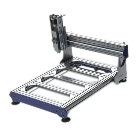
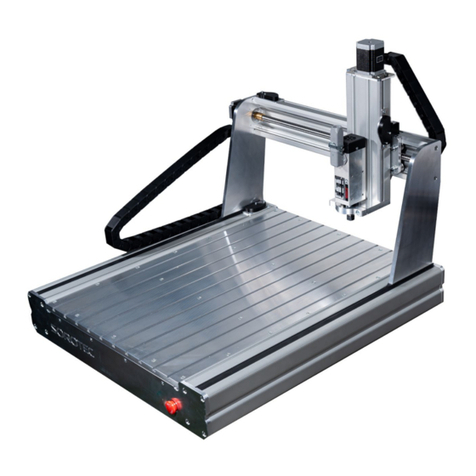
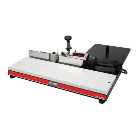
Sorotec COMPACT 0403 User manual

SOROTEC GmbH
Withig 12
77836 Rheinmünster
Tel.: +49 (0) 7227-994255-0
Fax: +49 (0) 7227-994255-9
E-Mail: [email protected]
Web: www.sorotec.de
Assembly instructions
CNC portal milling machine kit
Compact-Line
Version 2.1.0
MPF.CLxxxx.01.B

Page 2 / 22
Assembly instructions
Compact-Line kit
www.sorotec.de V 2.1.0
© 2022 Sorotec GmbH
Reproduction, duplication or translation, also in extracts, without the written approval of
Sorotec GmbH is not permitted. All rights under the Copyright Act remain the
Sorotec GmbH expressly reserved.
Technical changes reserved.
Made in Germany.

SOROTEC GmbH Tel.: +49 (0) 7227-994255-0
Wit77836 Rheinmünster E-Mail: sorotec@sorotec.de
Withig 12 Fax: +49 (0) 7227-994255-9 Web: www.sorotec.de Version 1.0 Januar 2021
Machine Parameters COMPACT-LINE
Mechanical Properes
TYPE: COMPACT
0403
COMPACT
0404
COMPACT
0405
COMPACT
0604
COMPACT
0605
COMPACT
0804
COMPACT
0805
COMPACT
1005
COMPACT
1007
Travel mm: X: 420 | Y: 310
Z: 140
X: 420 | Y: 410
Z: 140
X: 420 | Y: 510
Z: 140
X: 620 | Y: 410
Z: 140
X: 620 | Y: 510
Z: 140
X: 820 | Y: 410
Z: 140
X: 820 | Y: 510
Z: 140
X: 1020 | Y: 510
Z: 140
X: 1020 | Y: 710
Z: 140
Clamping area mm: X: 650 | Y: 306 X: 650 | Y: 406 X: 650 | Y: 506 X: 850 | Y: 406 X: 850 | Y: 506 X: 1050 | Y: 406 X: 1050 | Y: 506 X: 1250 | Y: 506 X: 1250 | Y: 706
Outer dimensions: L: 720 | B: 510
H: 750
L: 720 | B: 610
H: 750
L: 720 | B: 710
H: 750
L: 920 | B: 610
H: 750
L: 920 | B: 710
H: 750
L: 1120 | B: 610
H: 750
L: 1120 | B: 710
H: 750
L: 1320 | B: 710
H: 750
L: 1320 | B: 910
H: 750
Clearance under portal: Z: 170
Ball screw spindles:X: 16 x 10 mm | Y: 16 x 10 mm | Z: 16 x 5 mm | Tolerance class T07 | HIWIN | 2% preloaded by special balling, therefore free of play
Repeatability:approx. +/- 0.02 mm
Weight w/o accessories: approx. 48 kg approx. 55 kg approx. 62 kg approx. 67 kg approx. 76 kg approx. 79 kg approx. 90 kg approx. 96 kg approx. 102 kg
Linear guides: HIWIN linear guides 20mm | Medium preload carriages | Manufactured according to special specicaons for HIWIN Germany.
Clamping plate: Aluminum T-slot plate included.
Soware Parameters
Steps / revoluon: X: 3200 | Y: 3200 | Z: 3200 *1)
Steps / mm: X: 320 | Y: 320 | Z: 640 *1)
Max Feed Speed: X: 150 mm/s or 9 m/min | Y: 150 mm/s or 9 m/min | Z: 83 mm/s or 5 m/min *2)
Accelaraon mm/s²: X: 300 | Y: 300 | Z: 200 *2)
Remarks: *1) with a set 3200 microsteps of the output stage.
*2) with 48 V supply voltage and high-quality output stages.

Page 4 / 22
Assembly instructions
Compact-Line kit
www.sorotec.de V 2.1.0
Introduction
Congratulations on the purchase of our kit for a
Compact-Line CNC portal milling machine. We re-
commend reading through these instructions com-
pletely before assembly and then assembling the kit
step by step as described.
Fig. 1: Completed Compact-Line
Note:
All directions (left, right, front, back, up and
down) in this manual are based on the view as
shown in the gure above.
Required tools
The following tools and aids must or should be avai-
lable during assembly:
• Common hand tools, such as Allen keys,
screwdrivers, plastic hammer, etc.
• A work surface that is as at as possible and
the same size as the base frame
• Flat or try square, at least 300 mm long in
tolerance class 1 or better
• Dial indicator with stand / holder
• Torque wrench from 6 Nm to at least 25 Nm1)
1) To avoid distortion caused by unevenly tightened
screws, the use of a torque wrench for load-bearing
screws M5 to M8 is recommended. Adhering to the
prescribed screw tightening torque also prevents un-
intentional loosening during later operation of the
machine.
Optional accessories
The fully assembled machine can be further supple-
mented and adapted to your requirements with op-
tional accessories. In the Sorotec shop you will nd,
among other things:
• milling spindles
• base
• enclosure
• vacuum table
• control electronics
• control software
• minimum quantity lubrication
Caution!
Only carry out the work if you are familiar with the
necessary actions and suitable tools are available.
Sorotec GmbH assumes no liability for damage to
property or personal injury occurring during assem-
bly or operation of the CNC portal milling machine!
General information
Please assemble the kit as carefully and precisely
as possible - the accuracy of the nished machine
does not only depend on the quality of the delivered
components, but also to a high degree on the correct
assembly and exact alignment. Before assembly, all
components must be checked for burrs and rewor-
ked if necessary.

Infosheet Measure Screws
SOROTEC GmbH Tel.: +49 (0) 7 7-994 55-0
Withig 1 Fax: +49 (0) 7 7-994 55-9
77836 Rheinmünster E-Mail: sorotec@sorotec.de Version 1.0 Juli 0 0
Dimensions
Screw sizes are always given in the form of "diameter x length". In the case of metric screws, the diameter is
given by an M. Wood, sheet metal or plastic screws are not specially marked in the dimensioning. The unit of
measurement mm is usually not specified.
Examples:
M4 x 40 - metric screw with M4 thread and 40 mm length
3 x 5 - wood screw 3 mm in diameter and 5 mm in length
Web: www.sorotec.de
Diameter
Measurements are always made with the vernier caliper and on the
outside of the thread. To prevent the cutting edges of the measuring
jaws from slipping into the thread grooves, the screw is placed
lengthways between the jaws.
Length
Everything that disappears in the material is part of the
length of a screw. This means that measurements are taken
- ideally with the depth gauge of the caliper - from the
underside of the screw head to the end of the screw. Any
parts without a thread are also part of the length.
Exception countersunk screw
Because the head of the countersunk screw disappears
into the material, the head height here is part of the
length. So the length is measured over everything. But
really: Only with the countersunk screw!

Page 5 / 22
Assembly instructions
Compact-Line kit
www.sorotec.de V 2.1.0
Scope of delivery
Illustration Description Num-
ber
end plate Y right
CL.FT.015.01 1
end plate Y left
CL.FT.016.01 1
stop plate Z 1)
CL.FT.002.01 1
drive X:
xed brg. 4f CL.ZAN.FL16.H
ball screw 4s s. S. 6
recirculating ball nut 4k
t. brg. 4l CL.ZAN.LL16.H
1
drive Y:
xed brg. 5f CL.ZAN.FL16.H
ball screw 5s s. S. 6
recirculating ball nut 5k
t. brg. 5l CL.ZAN.LL16.H
1
drive Z 1):
xed brg. 6f CL.ZAN.FL16.H
ball screw 6s
recirculating ball nut 6k
CL.ZAN.KGS1605.0270KH
1
bracing Z 1):
left 7l CL .FT.004.01
right 7r CL.FT.005.01
1
ange bracket X
CL.FT.007.01 1
ange bracket Y
CL.FT.008.01 1
ange bracket Z
CL.FT.009.01 1
1) See page 6 for gantry elevation parts
1
2
3
4
5
6
7
8
9
10
Illustration Description Num-
ber
guide plate Z
CL.FT.001.01 1
rubber pad
(self-adhesive)
AL.EZB.0109
5
claw coupling
MZK.080.100.V25 2
carriage
ZFW.HGH20CA.ZA 10
linear rail X:
CL 04XX: 589 mm lg.
CL 06XX: 789 mm lg.
CL 08XX: 989 mm lg.
see page 6
2
linear rail Y above:
CL XX03: 420 mm lg.
CL XX04: 520 mm lg.
CL XX05: 620 mm lg.
see page 6
1
linear rail Y below:
CL XX03: 479 mm lg.
CL XX04: 579 mm lg.
CL XX05: 679 mm lg.
see page 6
1
linear rail Z 1):
220 mm lg.
320 mm lg.
CL.ZFS.HGR20R.0220
CL.ZFS.HGR20R.0320
1
1
motor ange Y
CL.FT.014.01 1
motor ange Z
CL.FT.006.01 1
11
12
13
14
15
16
17
18
19
20

Page 6 / 22
Assembly instructions
Compact-Line kit
www.sorotec.de V 2.1.0
Illustration Description Num-
ber
plate Z
CL.FT.003.01 1
portal beam below
see page 6 1
portal cheek: 1) :
left 23l CL.FT.010.01
right 23r CL.FT.011.01
1
1
Reference switch
with shim
EZB.T1 / AL.IS.001
3
switch carrier X
CL.FT.013.01 1
switch carrier Y
CL.FT.012.01 1
sled Y
CL.FT.017.01 1
face plate in the back
see page 6 1
front plate
see page 6 1
table top (pre-assembled)
see page 6 1
21
22
23
24
25
26
27
29
30
Illustration Description Num-
ber
angle 40x40
with cover cap
AL.PR.WS.084040
6
angle 45x45
AL.PR.WS.104545 4
portal beam (pre-ass.)
see page 6 1
timing belt Y
CL.ZAN.HTD3M100.300 1
belt wheel 36 teeth
bore 8 mm
AL.ZAN.HTD3M36.15.08
1
belt wheel 36 Zähne
bore 10 mm
CL.ZAN.HTD3M36.15.10
1
foot holder
CL.FT.018.01
1
drag chain holder
CL.FT.032.01 1
mounting bracket
for drag chain
CL.PR.BW.604020
1
cylindrical pin DIN6325
5x18 M6
AL.ZS.05.18
9
1) Teile zur Portalerhöhung siehe Seite 6
31
32
33
34
35
36
37
38
39
Z

Page 7 / 22
Assembly instructions
Compact-Line kit
www.sorotec.de V 2.1.0
Illustration Description Num-
ber
cylinder screw DIN912
M3x16
M4x12
M4x16
M4x20
M5x12
M5x16
M5x18
M5x20
M5x25
M8x16
6
14
8
4
14
38
46
87
8
6
hammer nut
Nut 8 M5
Nut 10 M5
Nut 10 M8
37
44
2
nut DIN934
M4 4
pan head screws
DIN7380
M12x30 4
cylinder screw DIN6912
M6x16
M6x20
M6x40
M8x12
M8x16
M8x20
6
2
16
2
4
12
A1
B1
B2
B3
C1
C2
C3
C4
C5
D1
H1
J1
J2
K
N1
E1
E2
E3
S1
S2
S3
Illustration Description Num-
ber
countersunk screw
DIN7991
M4x10
2
hammer head screw
M8x25 8
ange nut DIN6923
M8 8
washer DIN125
3,2
4,3
5,5
8,4
6
4
6
4
washer DIN9021
5,5
8,4
1
4
Note
The same number of standard parts is always
enclosed for all machines. In the case of smaller
sizes, standard parts may be superuous.
F
G
T
U
V
W
X
Y1
Y2

Page 8 / 22
Assembly instructions
Compact-Line kit
www.sorotec.de V 2.1.0
Order numbers of size-dependent parts
Machine
Description CL 04XX CL 06XX CL 08XX CL 10XX
4ball screw X
incl. nut (16 x 10)
CL.ZAN.KGS1610.0600KH CL.ZAN.KGS1610.0800KH CL.ZAN.KGS1610.1000KH CL.ZAN.KGS1610.1200KH
4ball screw X
incl. nut (16 x 5)
CL.ZAN.KGS1605.0600KH CL.ZAN.KGS1605.0800KH CL.ZAN.KGS1605.1000KH CL.ZAN.KGS1605.1200KH
15 linear rail X CL.ZFS.HGR20R.0588 CL.ZFS.HGR20R.0788 CL.ZFS.HGR20R.0988 CL.ZFS.HGR20R.1188
CL XX03 CL XX04 CL XX05 CL XX07
5ball screw Y
incl. nut (16 x 10)
CL.ZAN.KGS1610.0450KH CL.ZAN.KGS1610.0550KH CL.ZAN.KGS1610.0650KH BL.ZAN.KGS1610.0850KH
5ball screw Y
incl. nut (16 x 5)
CL.ZAN.KGS1605.0450KH CL.ZAN.KGS1605.0550KH CL.ZAN.KGS1605.0650KH BL.ZAN.KGS1605.0850KH
16 linear rail Y above CL.ZFS.HGR20R.0419 CL.ZFS.HGR20R.0519 CL.ZFS.HGR20R.0619 CL.ZFS.HGR20R.0819
17 linear rail Y below CL.ZFS.HGR20R.0478 CL.ZFS.HGR20R.0578 CL.ZFS.HGR20R.0678 CL.ZFS.HGR20R.0878
22 portal beam below CL.FT.026.01 CL.FT.027.01 CL.FT.028.01 CL.FT.055.01
28 face plate in the back CL.FT.020.01 CL.FT.021.01 CL.FT.022.01 CL.FT.053.01
29 front plate CL.FT.023.01 CL.FT.024.01 CL.FT.025.01 CL.FT.054.01
33 portal beam pre-ass. CL.FT.033.01 CL.FT.034.01 CL.FT.035.01 CL.FT.052.01
CL 0403 CL 0404 CL 0405 CL 0604
30 table top
(pre-assembled)
CL.FT.036.01 CL.FT.037.01 CL.FT.038.01 CL.FT.040.01
CL 0605 CL 0804 CL 0805 CL 1005
CL.FT.041.01 CL.FT.043.01 CL.FT.044.01 CL.FT.045.01
CL 1007
CL.FT.056.01
Order numbers for gantry elevation parts
• Portal cheek left CL.FT.046.01
• Portal cheek right CL.FT.047.01
• Plate Z axis CL.FT.048.01
• Bracing Z-axis left CL.FT.049.01
• Bracing Z-axis right CL.FT.050.01
• Ball screw including nut CL.ZAN.KGS1605.0320KH
• Linear guide rail short CL.ZFS.HGR20R.0274
• Linear guide rail long CL.ZFS.HGR20R.0370

Page 9 / 22
Assembly instructions
Compact-Line kit
www.sorotec.de V 2.1.0
Preliminary work
Pre-assembly of the
ball screws, spindle nuts and
bearing units Caution!
The pre-assembled recirculating ball nuts must not
be unscrewed from the recirculating ball spindles!
The ball nuts and ball screws are delicate and must
be handled with care!
In order not to damage the roller bearings during as-
sembly in the oating or xed bearing units, only the
outer bearing rings may be pressed/hit. Use a suita-
ble drive sleeve (tube) and oil the outer bearing ring
before assembly!
Install grease nipples (all drives)
• Equip all recirculating ball nuts with 90° angled
grease nipples (see gure 2, red arrow). Do not
fully tighten grease nipples yet so that you can
align them later.
Mount xed bearing (all drives)
• Push the rst bushing onto the ball screw.
• Push the xed bearing unit onto the ball screw.
• Push the second bushing onto the ball screw.
• Screw the shaft nut onto the ball screw
Attention: The collar of the shaft nut in the
direction of the xed bearing block.
• To adjust the axial play, tighten the shaft nut
until the ball screw can only be turned with
diculty in the xed bearing unit. Then carefully
loosen the shaft nut a little (approx. 5 °) until the
ball screw can easily be turned again.
• Screw the stud bolts into the threaded holes in
the shaft nut and tighten.
Install oating bearing (only X/Y drive)
• Press the roller bearing into the housing of the
oating bearing unit.
• Y-drive only: Push the oating bearing unit
onto the ball screw and attach the retaining ring
to the end of the ball screw.
Note
Floating and xed bearings are easy to distingu-
ish: the xed bearings have four mounting holes,
the oating bearings only two.
Fig. 2: Assembly of the grease nipples and spindle bearings

Page 10 / 22
Assembly instructions
Compact-Line kit
www.sorotec.de V 2.1.0
Assembly X axis
Fig. 3: Slot table with drive and guide parts
4
29
28
30
14
• Screw the linear rail 15 to the prole with
cylinder head screws M5x20 C4 uand slot 10
T-nuts M5 J1 ; the reference edge of the linear
rail marked with an arrow must be in contact with
the milled stop edge of the prole over its entire
length (see Figure 4).
• Tighten the screws evenly starting in the
middle and working outwards. Tightening torque:
6 Nm
• Repeat the work steps with the second prole
and second linear rail.
Note
The sealing plugs for the holes in the guide rails
prevent the accumulation of dirt and chips, which
could otherwise damage the sealing lips of the
carriages.
• Insert the sealing plugs into the holes in the
guide rails. Make sure they sit ush.
Fig. 4: Assembly of linear rails; Note the stop edge
C4
30
15
Note
When installing a bracket 32 on a component
without fastening grooves, the centering tabs on
the bracket must rst be removed (red arrows in
Figure 5). This can be done by breaking o with
a screwdriver, ling or grinding.
Fig. 5: Centering tabs on mounting bracket
32
These brackets are not installed on narrow ma-
chines with the width „03“! Accordingly, the work
steps for bracket assembly are omitted.

Page 11 / 22
Assembly instructions
Compact-Line kit
www.sorotec.de V 2.1.0
• Slide two carriages 14 onto the linear rails on
each side; the following should be noted:
- Ground, blank surfaces on the long sides
of the carriage point upwards towards the
tabletop.
- Equip the carriage with straight grease
nipples so that they point outwards (red
arrows in Figure 6).
• Screw the end plates 28 / 29 to the proles
with 2 at-head screws M12x30 N1 each;
Slightly counter-tighten the screws.
Note
„At the back“ of the Compact-Line slot table is
where there are four threaded holes on the un-
derside for mounting the xed bearing of the X-
spindle.
• Screw the bracket 32 to the underside of the
table top with M8x16 screws S2 and washers
X; Slightly counter-tighten the screws.
• Screw the brackets 32 to both end plates 28
/ 29 with cylinder head screws M8x20 S3 and
ange nuts T; Slightly counter-tighten the
screws.
• Tighten the mounting screws in the following
order:
- pan head screws
(end plates on proles of the table top)
- cylinder screws (angles on table top)
- cylinder screws / ange nuts (angles on end
plates)
Fig. 6: Carriage X, end plates and brackets
N1
29
N1
32
30
32
14
14 28
• Guide the ball screw 4s through the hole in
the front plate and screw the xed bearing 4f to
the table top with 4 cylinder screws M6x40 E3 ;
Slightly counter-tighten the screws.
• Slide the oating bearing unit 4l onto the free
end of the ball screw and screw it to the table top
with two cylinder screws M6x40 E3 ; Slightly
counter-tighten the screws.
• Install the snap ring on the end of the ball
screw. Fig. 7: X-axis spindle and reference switch
E3
X
25
24
U
A1
E3
30
4s
4f
4l
28
29
J2
S1
Note
The fastening screws of the bearing units are
only tightened after alignment. If necessary,
observe the additional instructions for the elect-
rical installation kit when installing the reference
switch.
• Equip the switch carrier X with two cylinder
screws M8x12 S1 and washers X, loosely
unscrew the hammer nuts J2 at the rear.
• Position switch carrier X 25 , threading
hammer nuts into the T-slot of the prole. Slightly
tighten the screws to turn the hammer nuts 90° in
the T-slot.
• Place the reference switch 24 with underlying
shim and screw it to the switch carrier 25 with
washers Uand cylinder head screws M3x16
A1 .

Page 12 / 22
Assembly instructions
Compact-Line kit
www.sorotec.de V 2.1.0
Assembly Y axis
Fig. 8: Portal and Y axis
9
2
5
14
17
16
23l
23r
33
1
• Drive the cylindrical pins Zinto the portal
cheeks 23l / 23r until they protrude 3 ... 4 mm on
the inside (see magnied picture 9).
• Place the portal panels with the cylinder pins
on the carriages and screw tight with cylinder
screws M5x20 C4 . Tightening torque: 6 Nm
• Insert the gantry beam 22 into the recesses of
the gantry stringers as shown in Figure 9 and
screw in place with cylinder screws M6x16 E1 ;
Slightly counter-tighten the screws.
• Degrease the surfaces to be glued and stick
one rubber pad 12 to the front and one to the
rear of the front panel (not shown).
Fig. 9: Installation of portal stringers and beam
28
C4
E1
22
23r
12
Z

Page 13 / 22
Assembly instructions
Compact-Line kit
www.sorotec.de V 2.1.0
• Equip linear rails 16 / 17 from above with
cylinder screws C3 and screw on slot 8 hammer
nuts H1 below.
• Place the linear rails on the proles of the
portal beam 33 in such a way that the reference
edges of the linear guides marked with arrows
point to the milled stop edges (see Figure 10).
• Center the linear rails on the proles and
slightly counter-tighten the screws to turn the
hammer nuts by 90° in the T-slot.
• Screw the linear rails to the proles; the
reference edges of the linear guides must lie
against the milled stop edges of the proles
along their entire length. Tightening torque: 6 Nm
• Insert the sealing plugs into the holes in the
guide rails. Make sure they sit ush.
Fig. 10: Reference edges of the linear rails
17
16 33
• Screw two brackets 31 to the lower prole of
the portal beam with cylinder head screws M5x16
C2 washers Wand T-nuts slot 8 H1
(magnifying glass below in picture 11); Slightly
counter-tighten the screws so that the angles can
still just be moved on the prole.
• Equip four brackets 31 with one cylinder
screw M5x25 C5 and one washer Weach and
loosely screw on a hammer nut H1 lat the back.
• Insert hammer nuts through the slot on the
back of the portal beam into the prole and screw
the angle (magnifying glass above in picture 11);
Slightly counter-tighten the screws so that the
angles can still just be moved.
• Place the portal beam on the two portal walls
as shown in Figure 11 and screw all angles to the
portal walls with cylinder screws M8x16 D1 ;
Slightly counter-tighten the screws
Fig. 11: Installation of the portal beam on the portal cheeks
C5
D1
C2
W
W
33
23l
23r
E1

Page 14 / 22
Assembly instructions
Compact-Line kit
www.sorotec.de V 2.1.0
Before aligning the X-axis, check that the following
screw connections are not yet tight, but only slightly
counter-tightened:
E1 Connections portal beam / portal cheeks
D1 Connections angles / portal cheeks
C5 Connections angles / portal beam
C2 Connections angles / prole
• If necessary, loosen screw connections and
tighten slightly.
• Move the portal several times from one end of
the base frame to the other end while gradually
tightening the screws. The order is the same as
for the loose check:
E1 Connections portal beam / portal cheeks
D1 Connections angles / portal cheeks
C5 Connections angles / portal beam
C2 Connections angles / prole
• Check whether the portal can be moved easily
over the entire travel path after tightening all
screws.
• Press the cover caps onto the angles. Fig. 12: Tighten the portal screw connection
E1
C5
D1
C2
D1
D1
C2
E1
22
• Tighten the X-axis ball nut grease tting so
that it faces the opening in the gantry beam (red
arrows in Figure 13).
• Screw the recirculating ball nut 4k to the
ange block X 8using cylinder screws M5x20
C4 ; Slightly counter-tighten the screws.
• Move the portal until the ange block X is
located above the lower portal beam 22 .
• Screw the ange bracket X to the portal beam
using cheese head screws M5x18 C3 ; Slightly
counter-tighten the screws.
Fig. 13: Screw connection of X-spindle nut and beam
C4
4k
22
C3

Page 15 / 22
Assembly instructions
Compact-Line kit
www.sorotec.de V 2.1.0
• Move the gantry forward as far as possible by
turning the ball screw 4s (red arrows in Fig. 14).
• Tighten the oating bearing 4l mounting
screws E3 . Tightening torque: 10 Nm.
• Tighten the retaining screws C4 of the
recirculating ball nut 4k on the ange bracket X
8. Tightening torque: 6 Nm.
• Carefully tighten the fastening screws C3 of
the ange bracket X on the beam.
Fig. 14: Tightening the X-spindle screw connections
E3
4s
4l
C3
• Move the gantry backwards by turning the ball
screw (red arrow in Figure 15) until the fastening
screws of the xed bearing are just accessible.
• Tighten the xed bearing mounting screws.
Tightening torque: 10 Nm
Fig. 15: Tightening the X spindle xed bearing
C3
E3
E3
C3
4f
4s
• Drive the cylindrical pins Zfrom the back into
the sled Y 27 until they protrude by about
3 ... 4 mm.
Fig. 16: Cylindrical pins in sled Y
Z
27

Page 16 / 22
Assembly instructions
Compact-Line kit
www.sorotec.de V 2.1.0
• Slide one carriage 14 onto the upper linear
rail 16 and two carriages 14 onto the lower
linear rail 17 ; the following must be observed:
- Ground, blank surfaces on the long sides of
the carriage point upwards
- Equip the lower carriage with straight grease
nipples so that they point outwards (red
arrows below in Figure 17).
- Equip the upper carriage with a 45° grease
nipple so that it points upwards to the left (red
arrow above in Figure 17).
• Place sled Y 27 with the cylinder pins on the
lower carriage and screw with cylinder screws
M5x12 C1 verschrauben. Tightening torque:
6 Nm
• Screw carriage Y to the upper carriage; Slightly
counter-tighten the screws.
• Move carriage Y back and forth several times
as far as possible to the left and right on the
linear rails; while doing so, gradually tighten
the fastening screws of the upper carriage.
Tightening torque: 6 Nm
Fig. 17: Mounting sled Y on the portal
14
16
17
27
Z
14
• Guide the ball screw 5s behind the sled Y 27
as shown. Screw loose bearing 5l with 2 and
xed bearing 5f with 4 cylinder screws M6x40
E3 to the portal beam 33 ; Slightly counter-
tighten the screws
• Tighten the grease tting on the ball nut 5k
sso that it faces the opening in the gantry beam
(red arrows in Figure 18).
• Screw the recirculating ball nut 5k to the
ange bracket Y 9musing cylinder screws
M5x20 C4 ; Slightly counter-tighten the screws.
• Move sled Y so that the carriage can be
mounted to the ange block Y with cylinder
screws M5x16 C2 ; Slightly counter-tighten the
screws.
• Move sled Y to the xed bearing by turning
the ball screw until the xing screws of the xed
bearing are just accessible.
Fig. 18: Installation of the Y spindle
C4 C2
5k
33
5f
5l
5s
27
12
9
E3
E3 E3
E3

Page 17 / 22
Assembly instructions
Compact-Line kit
www.sorotec.de V 2.1.0
• Tighten the xed bearing mounting screws E3 .
Tightening torque: 10 Nm
• Carefully tighten the retaining screws C4 of
the recirculating ball nut on the ange bracket Y.
Tightening torque: 6 Nm
• Move sled Y towards the loose bearing by
turning the ball screw until the fastening screws
E3 of the loose bearing are just accessible.
• Tighten the oating bearing mounting screws.
Tightening torque: 10 Nm
• Degrease the adhesive surfaces and stick the
rubber pads 12 on both sides of the sled Y (see
Figure 18).
• Screw end plate Y right 1to the portal beam
using cheese head screws M8x20 S3 .
Fig. 19: Assembly of the right end plate
S3
1
33
• Screw the motor ange Y 19 to the portal
beam 33 using cylinder screws M6x20 E2 it is
important to ensure that the recesses in the
motor ange (red arrows in Figure 20) point
outwards and that the motor ange is aligned at
an angle.
• Push the toothed belt wheel 36 as far as
possible onto the shoulder of the ball screw and
x it with the locking screw.
• Screw end plate Y left 2to the portal beam
using cylinder screws M8x20 S3 .
Fig. 20: Assembly of motor ange Y and left end plate
E2
S3
19
33
2
36

Page 18 / 22
Assembly instructions
Compact-Line kit
www.sorotec.de V 2.1.0
Note
The switch carrier Y is mounted on the left out-
side on the prole of the portal beam. When
installing the reference switch, observe the addi-
tional instructions for the electrical installation kit,
if necessary.
Fig. 21: Mounting reference switch Y-axis
24
H1
C1
26
U
A1
• Equip the switch carrier Y with two screws C1
and loosely screw on the hammer nuts H1 at the
back.
• Position switch carrier Y 26 , threading
hammer nuts into the T-slot of the prole. To turn
the T-nuts 90° in the T-slot, tighten the screws
slightly.
• Place the shim between the reference switch
24 and the switch carrier Y 26 and screw it
ush with the outer edge of the prole using
cylinder screws M3x16 A1 and washers U.

Page 19 / 22
Assembly instructions
Compact-Line kit
www.sorotec.de V 2.1.0
Assembly Z axis
Fig. 22: Completely assembled Z-axis on the mechanically fully assembled Compact-Line
• Drive the cylindrical pins Zinto the guide
plate Z 11 until they protrude by about
3 ... 4 mm.
• Screw the carriage 14 to the guide plate with
cylinder screws M5x16 C2 The following must
be observed:
- ground, blank surface on the long sides of
the carriage point to the outer edges of the
plate
- The lubricating nipples on the carriages point
outwards. If necessary, turn the lubricating
nipples or screw them to the opposite end
• Slightly counter-tighten the screws
• Slide the linear rail 18 into the two carriages
as shown in Figure 23. Press the carriage with
the linear rail against the cylindrical pins and
screw the two carriages tight in this position.
Tightening torque: 6 Nm
• Remove cylindrical pins (were only required for
alignment during assembly).
• Degrease the adhesive surface and stick a
rubber pad 12 to the guide plate Z.
Note
The fastening screws of the carriages
are only tightened during alignment.
Fig. 23: Assembly of the carriages
14
14
Z
C2
C2
Z
14
11
12
This manual suits for next models
11
Table of contents
Other Sorotec Power Tools manuals
