Sorotec COMPACT 0605 User manual

SOROTEC GmbH
Withig 12
77836 Rheinmünster
Tel.: +49 (0) 7227-994255-0
Fax: +49 (0) 7227-994255-9
E-Mail: [email protected]
Web: www.sorotec.de
Assembly instructions
CNC portal milling machine kit
Basic-Line
Version 2.3.3
MPF.BLxxxx.01.B

Page 1/26
Assembly instructions
Basic-Line kit
www.sorotec.de V 2.3.3
Technical specications
Basic-Line 0605 0607 1005 1007
Travel X: 650 mm
Y: 530 mm
Z: 140 mm
X: 650 mm
Y: 730 mm
Z: 140 mm
X: 1050 mm
Y: 530 mm
Z: 140 mm
X: 1050 mm
Y: 730 mm
Z: 140 mm
Clearance
under portal
180 mm 180 mm 180 mm 180 mm
Clamping area X: 840 mm
Y: 530 mm
X: 840 mm
Y: 730 mm
X: 1240 mm
Y: 530 mm
X: 1240 mm
Y: 730 mm
Outer dimensions L: 950 mm
B: 790 mm
H: 820 mm
L: 950 mm
B: 990 mm
H: 820 mm
L: 1350 mm
B: 790 mm
H: 820 mm
L: 1350 mm
B: 990 mm
H: 820 mm
Ball screw spindles
Tolerance class T07
X: 16 x 10 mm
Y: 16 x 10 mm
Z: 16 x 5 mm
X: 16 x 10 mm
Y: 16 x 10 mm
Z: 16 x 5 mm
X: 16 x 10 mm
Y: 16 x 10 mm
Z: 16 x 5 mm
X: 16 x 10 mm
Y: 16 x 10 mm
Z: 16 x 5 mm
Weight without
accessories
approx. 46 kg approx. 52 kg approx. 50 kg approx. 57 kg
© 2023 Sorotec GmbH
Reproduction, duplication or translation, also in extracts, without the written approval of
Sorotec GmbH is not permitted. All rights under the Copyright Act remain the
Sorotec GmbH expressly reserved.
Technical changes reserved.
Made in Germany.

Page 2/26
Assembly instructions
Basic-Line kit
www.sorotec.de V 2.3.3
Introduction
Congratulations on the purchase of our kit for a
Basic-Line CNC portal milling machine. We recom-
mend reading through these instructions completely
before assembly and then assembling the kit step by
step as described.
Required tools
The following tools and aids must or should be avai-
lable during assembly:
• Common hand tools, such as Allen keys,
screwdrivers, plastic hammers, etc.
• Work surface as at as possible in the size of
the base frame
• Flat or stop angle, at least
• 300 mm long in tolerance class 1 or better
• Dial indicator with stand / holder
• Torque wrench from 6 Nm up to
• at least 25 Nm1)
1) In order to avoid warping due to screws tightened
unevenly, the use of a torque wrench for load-bearing
screws M5 to M8 is recommended. By observing the
prescribed tightening torque also prevents unwanted
loosening during later operation of the machine.
Optional accessories
The fully assembled machine can be supplemented
and adapted to your requirements with optional ac-
cessories. In the Sorotec shop you will nd:
• Performance Kit 2)
• Milling spindles
• Electrical installation kit
• Control electronics
• Control software
• T-slot plate
• Vacuum table
• Minimum quantity lubrication
Caution!
Only carry out the work if you are familiar with the
necessary actions and suitable tools are available.
Sorotec GmbH assumes no liability for damage to
property or personal injury occurring during assem-
bly or operation of the CNC portal milling machine!
General information
Please assemble the kit as carefully and precisely
as possible - the accuracy of the nished machine
does not only depend on the quality of the delivered
components, but also to a high degree on the correct
assembly and exact alignment. Before assembly, all
components must be checked for burrs and rewor-
ked if necessary.
2) recommended for processing non-ferrous metals

Infosheet Measure Screws
SOROTEC GmbH Tel.: +49 (0) 7 7-994 55-0
Withig 1 Fax: +49 (0) 7 7-994 55-9
77836 Rheinmünster E-Mail: sorotec@sorotec.de Version 1.0 Juli 0 0
Dimensions
Screw sizes are always given in the form of "diameter x length". In the case of metric screws, the diameter is
given by an M. Wood, sheet metal or plastic screws are not specially marked in the dimensioning. The unit of
measurement mm is usually not specified.
Examples:
M4 x 40 - metric screw with M4 thread and 40 mm length
3 x 5 - wood screw 3 mm in diameter and 5 mm in length
Web: www.sorotec.de
Diameter
Measurements are always made with the vernier caliper and on the
outside of the thread. To prevent the cutting edges of the measuring
jaws from slipping into the thread grooves, the screw is placed
lengthways between the jaws.
Length
Everything that disappears in the material is part of the
length of a screw. This means that measurements are taken
- ideally with the depth gauge of the caliper - from the
underside of the screw head to the end of the screw. Any
parts without a thread are also part of the length.
Exception countersunk screw
Because the head of the countersunk screw disappears
into the material, the head height here is part of the
length. So the length is measured over everything. But
really: Only with the countersunk screw!

Page 3/26
Assembly instructions
Basic-Line kit
www.sorotec.de V 2.3.3
Scope of delivery
Illustration Description Number
End plate Y on the left
BL.FT.007.01 1
End plate Y on the right
BL.FT.008.01 1
Stop plate Z
BL.FT.013.01 1
Drive X:
xed bearing 4F
CL.ZAN.FL16.H
Ball screw 4S
see page 6
Recirc. ball nut 4K
readily mounted on ball screw
oating bearing 4L
BL.FT.017.01 and
AL.ZAN.LA6000RS
1
1
1
1
Drive Y:
xed bearing 5F
CL.ZAN.FL16.H
Ball screw 5S
see page 6
Recirc. ball nut 5K
readily mounted on ball screw
oating bearing 5L
CL.ZAN.LL16.H
1
1
1
1
Drive Z:
xed bearing 6F
CL.ZAN.FL16.H
Ball screw 6S
ZAN.NTS.KGS1605.0270.M
Recirc. ball nut 6K
readily mounted on ball screw
1
1
1
Stieners Z:
left 7L / right 7R
BL.FT.022.01
2
1
2
3
4
5
6
7
Illustration Description Number
Base plate Z
BL.FT.012.01 1
Flange bracket X
BL.FT.018.01 1
Flange bracket Y
BL.FT.019.01 1
Flange bracket Z
BL.FT.020.01 1
Flange plate
BL.FT.016.01 1
Device base
(self-adhesive)
AL.EZB.0109
7
Claw clutch
MZK.080.100.V25 3
Carriage
ZFW.NTS.HGH20CA
5
(7)
Linear rail X
see page 6 2
8
9
10
11
12
13
14
15
16

Page 4/26
Assembly instructions
Basic-Line kit
www.sorotec.de V 2.3.3
Illustration Description Number
Linear rail Y
see page 6 2
Linear rail Z
(300 mm lg.)
BL.ZFS.HGR20R.0300
1
Motor ange Z
BL.FT.011.01 1
Plate Z
BL.FT.010.01 1
Portal beam
(preassembled)
see page 6
1
Portal beam
see page 6 1
Portal cheek:
left 23L BL.FT.005.01
right 23R BL.FT.004.01
1
1
Prole 10 45 x 90 light
see page 6
3
(4)
Prole 10 45 x 90
heavy (819 mm lg.)
see page 6
2
17
18
19
20
21
22
23
24
25
Illustration Description Number
Prole 5 20 x 20
BL.PR.0520201N.0372 2
Reference switch
with shim
EZB.T1 / AL.IS.001
3
Switch carrier X
CL.FT.013.01 1
Switch carrier Y
BL.FT.021.01 1
Sled Y
BL.FT.009.01 1
Face plate in the back
see page 6 1
Front plate
see page 6 1
Angle 20 x 20
BL.PR.W.052020
including cover
5
Angle 40 x 40
AL.PR.WS.084040
including cover
6
26
27
28
29
31
32
33
34
35

Page 5/26
Assembly instructions
Basic-Line kit
www.sorotec.de V 2.3.3
Illustration Description Number
Angle 45 x 45
AL.PR.WS.104545
8
(12)
Drag chain holder
CL.FT.032.01 1
Tapered grease nipple
M6 x 1
ZB.HI.SN008
2
Grease nipple 90°
M6 x 1
ZB.HI.SN003
3
Cylinder head screw DIN 912
M3 x 14 A1 MED.SMZ8.8V.03.014
M3 x 16 A2 MED.SMZ8.8V.03.016
M4 x 16 B1 MED.SMZ8.8V.04.016
M4 x 20 B2 MED.SMZ8.8V.04.020
M4 x 25 B3 MED.SMZ8.8V.04.025
M5 x 12 C1 MED.SMZ8.8V.05.012
M5 x 14 C2 MED.SMZ8.8V.05.014
M5 x 16 C3 MED.SMZ8.8V.05.016
M5 x 18 C4 MED.SMZ8.8V.05.018
M5 x 20 C5 MED.SMZ8.8V.05.020
M5 x 22 C6 MED.SMZ8.8V.05.022
M5 x 25 C7 MED.SMZ8.8V.05.025
M6 x 14 D1 MED.SMZ8.8V.06.014
M6 x 35 D2 MED.SMZ8.8V.06.035
M6 x 50 D3 MED.SMZ8.8V.06.050
Sliding block 5 M5
3D.PR.NS.05M5S
Hammer nut
Slot 8 M5 G1 AL.PR.HM.08M5.017
Slot 8 M6 G2 AL.PR.HM.08M6.017
Slot 10 M5 H1 AL.PR.HM.10M5.030
Slot 10 M6 H2 AL.PR.HM.10M6.030
Slot 10 M8 H3 AL.PR.HM.10M8.030
36
37
SN
SM
F1
Illustration Description Number
Hammer screw
Slot 10 M8 x 20 J
enclosed with angle
Flat headed screw ISO 7380
M5 x 8 K1 MED.SMF10.9.05.008
M5 x 20 K2 MED.SMF10.9.05.020
M6 x 16 K3 MED.SMF10.9.06.016
M6 x 25 K4 MED.SMF10.9.06.025
M8 x 16 K5 MED.SMF10.9.08.016
M12 x 30 K6 MED.SMF10.9.12.030
Mounting bracket
drag chain
CL.PR.BW.604020
1
Cylinder head screw DIN 6912
M5 x 10 L1 MED.SMZNK8.8V.05.010
M5 x 16 L2 MED.SMZNK8.8V.05.016
M6 x 40 M1 MED.SMZNK8.8V.06.040
M8 x 20 N1 MED.SMZNK8.8V.08.020
Nut DIN 934
M3 OMED.SMU0.8V.03
M4 PMED.SMU0.8V.04
Flange nut DIN 6923
M8 Q
enclosed with angle
Washer DIN 125
3,2 UMED.SUS.V.03
8,4 XMED.SUS.V.08
Dowel pin hard DIN 6325
5 x 18 mm Z
AL.ZS.05.18
38

Page 6/26
Assembly instructions
Basic-Line kit
www.sorotec.de V 2.3.3
Order numbers of size-dependent parts
Maschine
Bezeichnung BL 0605 BL 0607 BL 1005 BL 1007
4S Ball screw X ZAN.NTS.KGS1610.0800.M ZAN.NTS.KGS1610.0800.M ZAN.NTS.KGS1610.1200.M ZAN.NTS.KGS1610.1200.M
5S Ball screw Y ZAN.NTS.KGS1610.0650.M ZAN.NTS.KGS1610.0850.M ZAN.NTS.KGS1610.0650.M ZAN.NTS.KGS1610.0850.M
16 Linear rail X BL.ZFS.HGR20R.0817.BL BL.ZFS.HGR20R.0817.BL BL.ZFS.HGR20R.1217.BL BL.ZFS.HGR20R.1217.BL
17 Linear rail Y BL.ZFS.HGR20R.0622.BL BL.ZFS.HGR20R.0822.BL BL.ZFS.HGR20R.0622.BL BL.ZFS.HGR20R.0822.BL
21 Portal beam BL.FT.023.01 BL.FT.028.01 BL.FT.023.01 BL.FT.028.01
22 Portal beam BL.FT.003.01 BL.FT.024.01 BL.FT.003.01 BL.FT.024.01
24 Prole 10 45 x 90 light BL.PR.104590L.0395 BL.PR.104590L.0595 BL.PR.104590L.0395 BL.PR.104590L.0595
25 Prole 10 45 x 90
heavy
BL.PR.104590S.0819 BL.PR.104590S.0819 BL.PR.104590S.1219 BL.PR.104590S.1219
32 Face plate back BL.FT.001.01 BL.FT.025.01 BL.FT.001.01 BL.FT.025.01
33 Face plate front BL.FT.002.01 BL.FT.026.01 BL.FT.002.01 BL.FT.026.01

Infosheet spindle bearings
SOROTEC GmbH Tel.: +49 (0) 7227 994255 0
Withig 12 Fax: +49 (0) 7227 994255 9
77836 Rheinmünster E Mail: sorotec@sorotec.de Version 1.0 März 2023
Floating bearings are not "loose bearings"
When storing a shaft in a machine, the thermal linear expansion must always be taken into account in the
design. In the case of a ball screw made of high alloy steel, for example, with a length of 0.1 ... 0.2 mm per
meter per 10 Kelvin temperature difference, this is quite considerable the additional tenths have to go
somewhere.
If the roller bearings were to be firmly connected at the ends both to the shaft and to the surrounding housing,
considerable axial stress would quickly arise as a result of thermal expansion. The bearings would be severely
overloaded and would wear out after a short time; Gradually louder, grinding rolling noises are the alarm signal
for bearing damage at the end.
Web: www.sorotec.de
Conflicting requirements
For this reason, the fit between the bearing seat on the shaft and
the inner ring of the bearing as well as that between the outer ring
and the bore in the housing is very tight on the fixed bearing.
Great forces may be required for assembly (plastic hammer, if
necessary driving sleeve for the inner ring), the use of heat and/or
cold to expand or shrink the components can also be helpful. In
any case, use oil!
At the floating bearing, a firm clamping should only guarantee the
guidance of the shaft radially (so that it does not "slack around"),
but it should be movable in the longitudinal direction to allow
thermal expansion without the build up of tension forces. The
mobility can take place either between the shaft and the inner ring
of the bearing or between the outer ring and the housing seat.
The bearing must not jam in one of the seats. However, the seat
must not be too loose either: even before any disruptive radial
mobility comes into play, one of the rings could begin to "wander"
and gradually wear down the seat on the shaft or in the housing.
Compromise: tight but not clamped
In practice, a workable compromise is usually reached by sliding the floating bearing tightly onto the end of the
shaft, but without using much force. How large the force may be is at the discretion of the machine builder. The
span of justifiable handling ranges from energetic pressing by hand (but without hammer blows) to pushing it onto
the “sucking” seat.
Important to know: Standard parts such as bearings also have tolerances. With the problem discussed here, a few
thousandths of a millimeter can make a big difference one bearing is jammed, the next can be easily pushed on.
If possible, trying out several bearings can lead to success. Otherwise it has to be reworked. This is also normal
and commonplace in mechanical engineering.
Regrind bearing seat
If necessary, use a piece of abrasive fleece to make the loose bearing seat of the ball screw sufficiently free to
move. Alternatively, you can also use very fine grain sandpaper. Make sure you work evenly all around. Try
frequently to slide the bearing onto the oiled seat. If the inner ring is tight without binding, the floating bearing is
installed correctly.
Fixed bearing (above) and floating
bearing in a Sorotec Alu-Line
Attention!
If you have to pull of a bearing that accidentally stuck by
gripping the outer ring, it is likely badly damaged and should
no longer be used.

Page 7/26
Assembly instructions
Basic-Line kit
www.sorotec.de V 2.3.3
Preparatory work
Preparing angles for surface
mounting
When installing an angle 34 or 35 on a component
without fastening grooves, the centering tabs on the
angle must be removed before installation (see Figu-
re 1). This can be done by breaking o with a screw-
driver or ling / sanding.
Fig. 1: Centering tabs on mounting bracket
35
34
Pre-assembly of the ball screws,
spindle nuts and bearing units
Caution!
The pre-assembled recirculating ball nuts must not
be turned o the ball screws!
The ball nuts and ball screwsare sensitive and must
be handled with care!
Install the grease nipple
(all drives):
Equip all ball nuts with 90° angled grease nipples
(see picture 2). Do not fully tighten the grease nipples
to be able to align them later.
Fig 2: Bore and thread for grease nipples

Page 8/26
Assembly instructions
Basic-Line kit
www.sorotec.de V 2.3.3
Mount the xed bearings
• Push the rst bushing onto the ball screw.
Place the xed bearing unit on the ball screw.
• Push the second bushing onto the ball screw.
• Screw the shaft nut onto the ball screw.
Attention: The collar of the shaft nut in the
direction of the xed bearing block.
• To adjust the axial play, tighten the shaft nut
until the ball screw can only be turned with
diculty in the xed bearing unit. Then carefully
loosen the shaft nut a little (approx. 5 °) until the
ball screw can easily be turned again.
• Screw the stud bolts into the threaded holes in
the shaft nut and tighten.
• X drive only: screw the xed bearing 4F to the
ange plate 12 ; Tighten the screws D2 slightly.
• Align the rear edges of the xed bearing and
ange plate in parallel and tighten the screws.
Fig. 3: Mounting xed bearings
Fig. 4: Fixed bearing on X-drive
Install oating bearing X drive
• Press the roller bearing into the housing.
Note:
In order not to damage the rolling bearing when in-
stalling it in the housing, only push / hit on the bearing
outer ring. Use a suitable drive sleeve (tube) and oil
the outer bearing ring before assembly!
• Place the oating bearing on the ball screw.
Install oating bearing Y drive
• Place the oating bearing unit on the ball
screw and attach the circlip to the end of the ball
screw.
Fig. 5: Rolling bearing assembly with drive sleeve
Fig 6: Floating bearing assembly
4L

Page 9/26
Assembly instructions
Basic-Line kit
www.sorotec.de V 2.3.3
Assembly X axis
and base frame
Note:
The following illustrations show the Basic-Line 0605
kit. The Basic-Line 1005 is installed analogously.
Fig. 7: Completely assembled base frame
• Screw the linear guide 16 to the prole 25 ;
The lower edge of the linear guide must lie along
the milled stop edge of the prole over its entire
length (see Figure 8).
• Tighten the screws evenly outwards in the
middle. Tightening torque: 6 Nm
• Repeat steps with a second prole and a
second linear guide.
Note:
The sealing plugs for the holes in the guide rails pre-
vent the accumulation of dirt and chips, which could
otherwise damage the sealing lips of the carriages.
• Insert the sealing plugs into the holes in the
guide rails. Make sure they sit ush.
Fig. 8: Linear guides on the stop edge (arrow)
16
H1
C4
Note:
The further assembly of the base frame is carried out
lying on its back, as shown in Figure 9. Fig. 9: Base frame in supine position
Page 10/26
Assembly instructions
Basic-Line kit
www.sorotec.de V 2.3.3
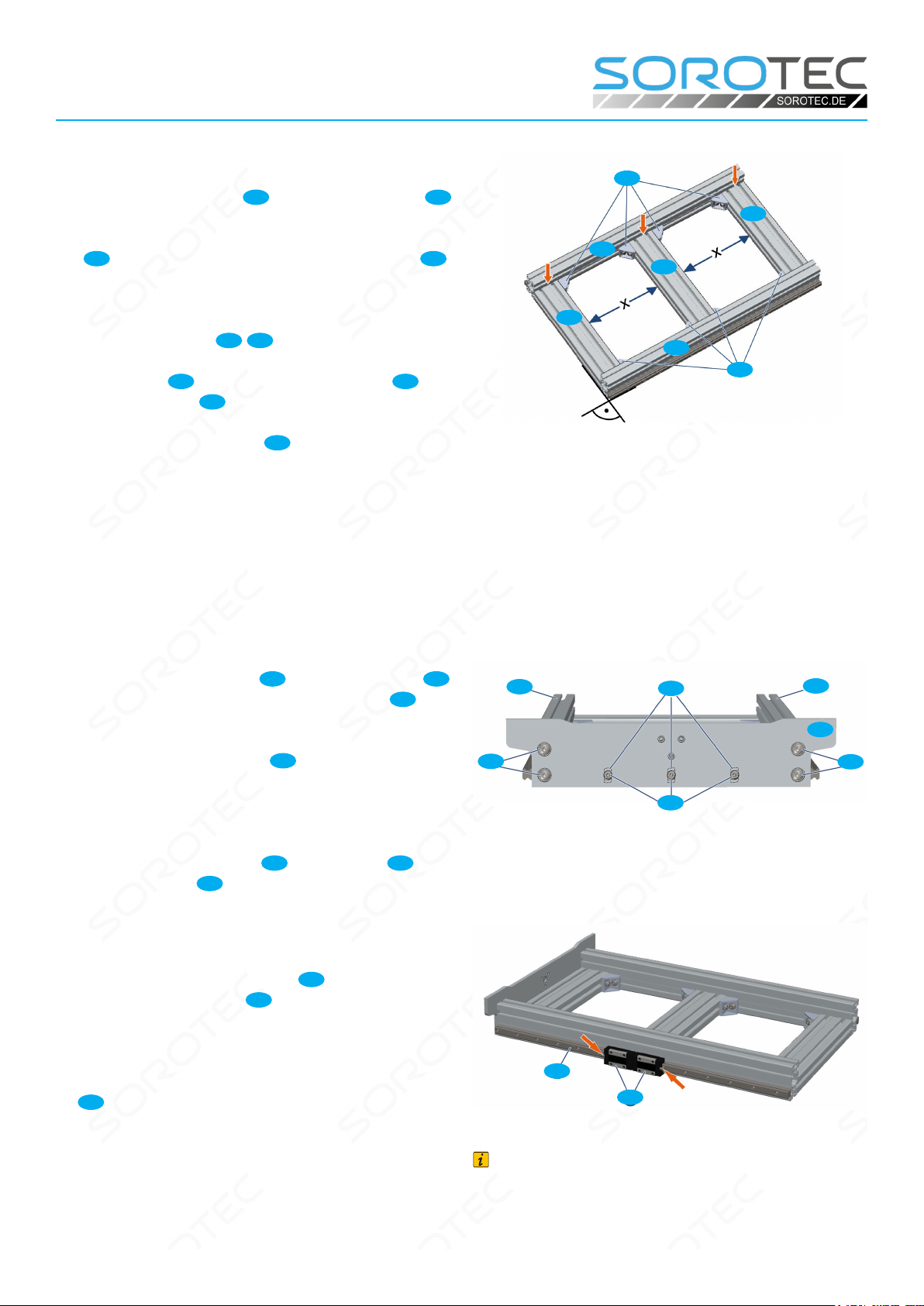
The base frame must be mounted in such a way that
there is an air gap of approx. 0.5 mm between the
end faces of the proles 24 and the long prole 25
for aligning the base frame (see red arrows in Figure
10). On the opposite side, the end faces of the pro-
les 24 must be in contact with the long prole 25 .
The base frame should be installed as stress-free as
possible.
• Lay out proles 24 /25 as shown on a at
work surface and loosely screw them together
with angles 36 . Use the hammer screws J
and ange nuts Qfor this.
• Move the inner prole 24 or inner proles
(1005) so that equally long elds (x) are created.
• Tighten the screws one after the other from an
outside corner (tightening torque: 25 Nm). Always
check the perpendicularity and parallelism of the
base frame and correct if necessary.
Fig. 10: Assembly of the base frame
36
36
25
24
24
24
25
• Fit three front screws K5 on the front plate 33
and loosely screw on three hammer nuts H3 on
the inside.
• Position the front plate 33 at the front,
threading the hammer nuts into the T-groove of
the prole. Tighten the screws slightly to turn the
hammer nuts 90° in the T-slot
• Screw front end plate 33 with proles 25 ;
Tighten screws K6 slightly.
• Tighten all front panel mounting screws.
Fig. 11: Mounting end plate on frame proles
K5
25
25
K6
33
K6
H3
• Push one or two carriages 15 on each side
onto the linear guides 16 . Please note:
smoothed, bare surfaces on the long sides of the
carriage point down towards the work surface.
• Load the carriage with straight grease nipples
SN so that they point outwards.
Fig. 12: Lubricating nipples on the carriage point outwards
Note:
The illustration shows the assembly with the Per-
formance Kit, i.e. with two carriages per side on the
guide of the X axis.
16
15

Page 11/26
Assembly instructions
Basic-Line kit
www.sorotec.de V 2.3.3
• Equip the rear faceplate 32 with three screws
N2 and loosel screw on three hammer nuts H3
on the inside.
• Position the rear end plate, threading hammer
nuts into the T-slot of the prole. Tighten the
screws slightly to turn the hammer nuts in the
T-slot by 90°.
• Screw the rear face plate to the proles with
at-head screws K6 ; Tighten screws slightly.
• Tighten all rear face plate mounting screws.
Fig. 13: Assembly of the rear face plate
32
H3
K6 K6
K5
25 25
• Place the pre-assembled X drive 4in the
base frame as shown in Figure 14.
• Screw the oating bearing to the front face
plate with socket head screws D1 ; Tighten
screws slightly.
• Insert two hammer nuts H2 in the groove of
the prole, turn them 90 ° and slide them under
the mounting holes of the xed bearing.
• Screw the xed bearing to the prole using
socket head screws D3 ; Tighten screws slightly.
• Insert four hammer nuts H1 in the grooves of
the prole, turn them 90° and slide them under
the mounting holes of the ange plate 12 .
• Screw the ange plate to the prole using
socket head screws C3 ; Tighten screws slightly.
Note:
The fastening screws C3 , D1 and D3 of the bearing
units 4L / 4F are not tightened until aligning.
For the following reference switch assembly, if ne-
cessary, observe the additional instructions for as-
sembly „Electrical installation kit“.
Fig. 14: Assembly of the X drive
D3
D3
H2
4F
4
12
C3
33
D1
4L
C3

Page 12/26
Assembly instructions
Basic-Line kit
www.sorotec.de V 2.3.3
• Equip switch carrier X 28 with screws K5 and
washers Xand loosely screw on two hammer
nuts H3 on the inside.
• Position switch carrier X as shown on the
xed bearing side of the base frame, threading
hammer nuts into the T-slot of the prole.
• Tighten the screws, turning the hammer nut
through 90° in the T-slot.
• Place the shim between the reference switch
and switch carrier X and screw on the reference
switch. Fig. 15: Assembly of the X reference switch
27
U
K5
28
H3
X
X
A1
Assembly of Y-axis / portal
Note:
The following illustration shows the assembly without
a performance kit, i.e. with one carriage per side on
the X axis.
Fig. 16: Fully assembled portal with Y axis

Page 13/26
Assembly instructions
Basic-Line kit
www.sorotec.de V 2.3.3
• Drive in dowel pins Zinto the portal cheeks
23L /23R until they protrude approximately 3 ... 4
mm on the inside.
• Place the portal cheeks with the cylinder pins on
the carriages 15 and screw them in with cylin-
der screws Z. Tightening torque: 6 Nm.
Remove pins after assembly.
Fig. 17: Assembly of the portal cheeks
23L 23R
C3 C3
Z15 Z
15
• Load the linear rails 17 from above with
cylinder screws C4 and screw on the hammer
nuts G1 from below.
Fig. 18: Assembly of the Y linear guides
17
21
17
• Place the linear rails on the proles of the
portal beam in such a way that the lower edges
of the linear guides marked with arrows in Figure
18 (detail) point to the milled stop edges.
• Align the linear rails in the center of the proles
and turn the screws slightly in order to turn the
hammer nuts by 90° in the T-slot.
• Screw the linear rails to the proles; continue
to watch the lower edges of the linear guides
matching the milled stop edges of the proles
over their entire length. Tightening torque: 6 Nm
• Insert the sealing plugs into the holes in the
guide rails. Make sure they sit ush.
• Load four angles 35 with one screw K4 each
and loosely screw on a hammer nut G2 at the
back.
• Insert the hammer nuts through the elongated
holes on the back of the gantry beam into
the prole and screw the brackets (Fig. 19,
magnifying glass above); Tighten the screws
slightly so that the angles can just be shifted.
• Screw two angles 35 with at-head screws
K3 and hammer nuts G2 to the lower prole of
the gantry beam 21 (Fig. 19, magnifying glass
below); Tighten the screws slightly so that the
angles can just be moved on the prole.
• Place the portal beam on the two portal cheeks
as shown and screw all angles to the portal
cheeks with at-head screws K3 and hammer
nuts G2 ; Tighten screws slightly. Fig. 19: Connection of portal beams and cheeks
K5
G2
21
23
K5
K4
G2
23
35
K3
35

Page 14/26
Assembly instructions
Basic-Line kit
www.sorotec.de V 2.3.3
• Insert the portal beam 22 as shown in Figure
20 in the recesses in the portal cheeks and
mount with cylinder screws D1 ; Tighten screws
slightly
• Degrease the adhesive surfaces and stick a
device foot 13 on the portal cheeks at the front
and rear.
Fig. 20: Installation of girder portal beam
D1
D1
13
13
13
13
22
• Before aligning the X axis (Figure 21), check
that the following screw connections are not yet
tight, but are only slightly tightened:
D1 Connections portal girder / portal cheeks
K5 Connections angle / portal cheeks
K4 Connections angle / portal beam
K3 Connections angle / prole
• If necessary, loosen screw connections and
fasten slightly.
• Move the portal several times from one end of
the base frame to the other end, gradually
tightening the screws in the following order:
D1 Connections portal girder / portal cheeks
K5 Connections angle / portal cheeks
K4 Connections angle / portal beam
K3 Connections angle / prole
Fig. 21: Align the X axis
D1
K3
K5
K4
K5
K3
K5
To adjust the parallelism of the base frame, some
screw connections are loosened on the side with the
air gap (see Fig. 10 and Fig. 22) so that the width of
the base frame can be shifted slightly.
• Loosen screw connections somewhat.
• Move the portal several times from one end
of the base frame to the other end and gradually
tighten the loosened screws again.
• Check whether the portal can be easily moved
over the entire travel path over the base frame
after all screws have been tightened. Fig. 22: Setting the parallelism of the basic frame

Page 15/26
Assembly instructions
Basic-Line kit
www.sorotec.de V 2.3.3
• Tighten the lubricating nipple of the
recirculating ball nut 4K so that it faces the rear
face plate.
• Mount the ball nut on the ange bracket X 9
using socket head screws C5 ; Tighten screws
slightly.
• Move the portal until the ange bracket X is
above the portal beam.
• Screw ange bracket X to the gantry beam
using socket head screws C7 ; Tighten screws
slightly.
Fig. 23: Mounting ange bracket
C7
C7
4K
C5
22
• Move the portal as far forward as possible by
turning the ball screw 4S .
• Tighten the xing screws D2 of the oating
bearing. Tightening torque: 10 Nm
• Tighten the xing screws C5 of the ball nut on
the ange bracket X (see Figure 23). Tightening
torque: 6 Nm
Fig. 24: Tighten oating bearing X-axis
4S
D2
• Carefully tighten the fastening screws C7 of
the ange bracket X on the gantry beam (see
Fig. 23).
• Move the portal backwards by turning the ball
screw so that the xing screws 4F of the xed
bearing are just accessible.
• Tighten the xing screws D3 of the xed
bearing. Tightening torque: 10 Nm
• Befestigungsschrauben der Flanschplatte 12
festziehen. Schraubenanzugsdrehmo-ment: 6
Nm Tighten the fastening screws C3 of the
ange plate C5 . Tightening torque: 6 Nm
Fig. 25: Festziehen Festlager und Flanschplatte X-Achse
D3
C3
4S
4F
12
C3
• Drive the dowel pins Zinto the Y slide 31
ush to the back.
Fig. 26: Dowel pins in sledge
31
Z

Page 16/26
Assembly instructions
Basic-Line kit
www.sorotec.de V 2.3.3
• Push one carriage 15 each onto the linear
rails 17 ; Please note the following:
- smoothed, bare surface on the long sides of
the carriage point upwards
- Grease nipples point to the left
(see picture 27)
• Place the slide Y 31 with the cylinder pins Z
on the upper carriage and screw them in with
cylinder screws C1 . Tightening torque: 6 Nm
• Screw carriage Y to the lower carriage; Tighten
screws slightly.
• Slide carriage Y back and forth on the linear
rails several times as far as possible; gradually
tighten the fastening screws of the lower
carriage. Tightening torque: 6 Nm
Fig. 27: Location of the grease nipples on the Y carriage
15
31
17
17
21
Z
• Guide the pre-assembled Y drive 5behind the
Y carriage as shown in Figure 28. Screw the
oating bearing 5L with 2 and the xed bearing
5F with 4 cylinder screws M1 to the portal
beam; Tighten screws slightly.
• Tighten the 90° lubrication nipple on the
recircula-ting ball nut 5K facing the opening.
• Mount the ball nut on the ange bracket Y 10
using pan head screws K2 ; Tighten screws
slightly.
• Slide the slide Y to the screw connection with
the ange bracket Y.
• Screw slide Y and ange bracket Y with socket
head screws C1 ; Tighten screws slightly
• Move the slide Y to the xed bearing by turning
the ball screw 5S until the xing screws of the
xed bearing are just accessible.
Fig. 28: Assembly of ange bracket and Y-slide
5S
M1 M1
21
31
M1
5F
K2
5K 10
C1
5L M1

Page 17/26
Assembly instructions
Basic-Line kit
www.sorotec.de V 2.3.3
• Tighten the xing screws of the xed bearing.
Tightening torque: 10 Nm
• Tighten the xing screws of the ball nut on the
ange bracket Y. Tightening torque: 6 Nm
• Carefully tighten the fastening screws of the
ange bracket Y.
• Move the slide Y to the oating bearing by
turning the ball screw until the fastening screws
of the oating bearing are just accessible.
• Tighten the xing screws of the oating
bearing. Tightening torque: 10 Nm
• Degrease the adhesive surfaces on the xed
bearing and oating bearing and stick on the
device feet 13 .
• Screw the right end plate Y 2to the gantry
beam using cylinder screws N1 .
• Screw the left end plate Y 1with cylinder
screws N1 on the portal beam.
Note:
The switch bracket Y 29 is mounted on the outside
left on the prole of the portal beam.
When installing the reference switch, observe the ad-
ditional instructions for the „Electrical installation kit“.
• Equip switch carrier Y 29 with two cylinder
head screws C2 and loosely screw on hammer
nuts G1 at the bottom.
• Position switch carrier Y, threading hammer
nuts into the T-slot of the prole. Tighten the
screws slightly to turn the hammer nuts in the
T-slot by 90°.
• Place the shim between the reference switch
27 and switch carrier Y and screw the reference
switch to the switch carrier Y using cylinder head
screws A2 and a washer U.
Fig. 29: Stick on the device feet as a buer
Fig. 30: Assembly of the right end plate
Fig. 31: Assembly of the left end plate
Fig. 32: Installation of Y reference switch
13
5F 13 5L
2N1
21
1
N1 21
G1
U
C2
A2
27
This manual suits for next models
3
Table of contents
Other Sorotec Power Tools manuals


