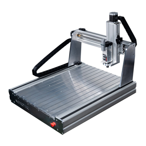
Sorotec ALU 0605 User manual

SOROTEC GmbH
Withig 12
77836 Rheinmünster
Tel.: +49 (0) 7227-994255-0
Fax: +49 (0) 7227-994255-9
E-Mail: [email protected]
Web: www.sorotec.de
Assembly instructions
CNC portal milling machine kit
Alu-Line
Version 2.0.0
MPF.ALxxxx.01.B

Page 2/33
Assembly Instructions
Alu-Line
www.sorotec.de V 2.0.0
© 2022 Sorotec GmbH
Reproduction, duplication or translation, also in extracts, without the written approval of
Sorotec GmbH is not permitted. All rights under the Copyright Act remain the
Sorotec GmbH expressly reserved.
Technical changes reserved.
Made in Germany.

SOROTEC GmbH Tel.: +49 (0) 7227-994255-0
Wit77836 Rheinmünster E-Mail: sorotec@sorotec.de
Withig 12 Fax: +49 (0) 7227-994255-9 Web: www.sorotec.de Version 1.0 January 2021
Machine parameters ALU-LINE
Mechanical characteriscs
TYPE:
ALU 0605 ALU 0607 ALU 0610 ALU 1105 ALU 1107 ALU 1110
Travel mm: X: 650 | Y: 550
Z: 220
X: 650 | Y: 750
Z: 220
X: 650 | Y: 1050
Z: 220
X: 1150 | Y: 550
Z: 220
X: 1150 | Y: 750
Z: 220
X: 1150 | Y: 1050
Z: 220
Clamping surface mm: X: 1000 | Y: 550 X: 1000 | Y: 750 X: 1000 | Y: 1050 X: 1500 | Y: 550 X: 1500 | Y: 750 X: 1500 | Y: 1050
Installaon
dimensions mm
L: 1050 | B: 960
H: 1080
L: 1050 | B: 1160
H: 1080
L: 1050 | B: 1560
H: 1080
L: 1550 | B: 960
H: 1080
L: 1550 | B: 1160
H: 1080
L: 1550 | B: 1460
H: 1080
Passage under portal mm: Z: 270
Ball screws:X: 16 x 10 mm | Y: 16 x 10 mm | Z: 16 x 5 mm | tolerance class T07
Repeatability:approx. +/- 0.02 mm
Weight w/o accessories: approx. 95 kg approx. 105 kg approx. 120 kg approx. 120 kg approx. 130 kg approx. 140 kg
Linear guides: HIWIN linear guides 20 mm | Medium preload carriage | Manufactured according to special specicaons for HIWIN Germany.
Clamping surface: Oponally available: aluminum T-slot plate, screen prinng plate
Soware parameters
Steps / revoluon: X: 3200 | Y: 3200 | Z: 3200 *1)
Steps / mm: X: 320 | Y: 320 | Z: 640 *1)
Max Feed Speed: X: 150 mm/s or 9 m/min | Y: 150 mm/s or 9 m/min | Z: 83 mm/s or 5 m/min *2)
Acceleraon
mm/s²: X: 300 | Y: 300 | Z: 200 *2)
Remarks: *1) with the power stage set to 3200 microsteps.
*2) with 48 V supply voltage and high-quality power ampliers.

SOROTEC GmbH Tel.: +49 (0) 7227-994255-0
Wit77836 Rheinmünster E-Mail: sorotec@sorotec.de
Withig 12 Fax: +49 (0) 7227-994255-9 Web: www.sorotec.de Version 1.0 January 2021
Machine parameters ALU-LINE HEAVY
Mechanical characteriscs
TYPE: ALU 1105 HEAVY ALU 1107 HEAVY ALU 1505 HEAVY ALU 1507 HEAVY ALU 1510 HEAVY ALU 2007 HEAVY ALU 2010 HEAVY ALU 2013 HEAVY
Travel mm: X: 1150 | Y: 550
Z: 220
X: 1150 | Y: 750
Z: 220
X: 1550 | Y: 550
Z: 220
X: 1550 | Y: 750
Z: 220
X: 1550 | Y: 1050
Z: 220
X: 2050 | Y: 750
Z: 220
X: 2050 | Y: 1050
Z: 220
X: 2050 | Y: 1350
Z: 220
Clamping surface mm: X: 1500 | Y: 550 X: 1500 | Y: 750 X: 1850 | Y: 550 X: 1900 | Y: 750 X: 1900 | Y: 1050 X: 2400 | Y: 750 X: 2400 | Y: 1050 X: 2400 | Y: 1350
Installaon
dimensions mm:
L: 1550 | B: 960
H: 1080
L: 1550 | B: 1160
H: 1080
L: 2000 | B: 960
H: 1080
L: 2000 | B: 1160
H: 1080
L: 2000 | B: 1460
H: 1080
L: 2450 | B: 1160
H: 1080
L: 2450 | B: 1460
H: 1080
L: 2450 | B: 1760
H: 1080
Passage under portal mm: Z: 270
Ball screws:X: 25 x 10 mm | Y: 16 x 10 mm | Z: 16 x 5 mm | tolerance class T07
Repeatability:approx. +/- 0.02 mm
Weight w/o accessories: approx. 180 kg approx. 200 kg approx. 210 kg approx. 210 kg approx. 220 kg approx. 210 kg approx. 240 kg approx. 270 kg
Linear guides: HIWIN linear guides 20 mm | Medium preload carriage | Manufactured according to special specicaons for HIWIN Germany.
Clamping surface: Oponally available: aluminum T-slot plate, screen prinng plate
Soware parameters
Steps / revoluon: X: 3200 | Y: 3200 | Z: 3200 *1)
Steps / mm: X: 320 | Y: 320 | Z: 640 *1)
Max Feed Speed: X: 150 mm/s or 9 m/min | Y: 150 mm/s or 9 m/min | Z: 83 mm/s or 5 m/min *2)
Acceleraon
mm/s²: X: 300 | Y: 300 | Z: 200 *2)
Remarks: *1) with the power stage set to 3200 microsteps.
*2) with 48 V supply voltage and high-quality power ampliers.

SOROTEC GmbH Tel.: +49 (0) 7227-994255-0
Wit77836 Rheinmünster E-Mail: sorotec@sorotec.de
Withig 12 Fax: +49 (0) 7227-994255-9 Web: www.sorotec.de Version 1.0 January 2021
Machine parameters ALU-LINE HEAVY GANTRY
Mechanical characteriscs
TYPE: ALU 1105 HEAVY GANTRY ALU 1107 HEAVY GANTRY ALU 1507 HEAVY GANTRY ALU 1510 HEAVY GANTRY ALU 2010 HEAVY GANTRY
Travel mm: X: 1150 | Y: 550
Z: 220
X: 1150 | Y: 750
Z: 220
X: 1550 | Y: 750
Z: 220
X: 1550 | Y: 1050
Z: 220
X: 2050 | Y: 1050
Z: 220
Clamping surface mm: X: 1500 | Y: 550 X: 1500 | Y: 750 X: 1900 | Y: 750 X: 1900 | Y: 1050 X: 2400 | Y: 1050
Installaon
dimensions mm
L: 1550 | B: 960
H: 1080
L: 1550 | B: 1160
H: 1080
L: 2000 | B: 1160
H: 1080
L: 2000 | B: 1460
H: 1080
L: 2450 | B: 1460
H: 1080
Passage under portal mm: Z: 270
Ball screws:X: 25 x 10 mm | Y: 16 x 10 mm | Z: 16 x 5 mm | tolerance class T07
Repeatability:approx. +/- 0.02 mm
Weight w/o accessories: approx. 190 kg approx. 200 kg approx. 220 kg approx. 230 kg approx. 250 kg
Linear guides: HIWIN linear guides 20 mm | Medium preload carriage | Manufactured according to special specicaons for HIWIN Germany.
Clamping surface: Oponally available: aluminum T-slot plate, screen prinng plate
Soware parameters
Steps / revoluon: X: 3200 | Y: 3200 | Z: 3200 *1)
Steps / mm: X: 320 | Y: 320 | Z: 640 *1)
Max Feed Speed: X: 150 mm/s or 9 m/min | Y: 150 mm/s or 9 m/min | Z: 83 mm/s or 5 m/min *2)
Acceleraon
mm/s²: X: 300 | Y: 300 | Z: 200 *2)
Remarks: *1) with the power stage set to 3200 microsteps.
*2) with 48 V supply voltage and high-quality power ampliers.

Page 6/33
Assembly Instructions
Alu-Line
www.sorotec.de V 2.0.0
Introduction
Congratulations on purchasing our kit for a CNC por-
tal milling machine from the Alu-Line. Before assem-
bly, we recommend reading through these instruc-
tions completely and then assembling the kit step by
step as described.
General information
Please assemble the kit as carefully as possible
and exact – the accuracy of the nished machine
depends not only on the quality of the delivered com-
ponents, but also to a large extent of correct assem-
bly and alignment. All components must be checked
prior to assembly to ensure they are free of burrs and
reworked if necessary.
Optional accessories
The fully assembled machine can be further supple-
mented and adapted to your requirements with op-
tional accessories. In the Sorotec shop you will nd,
among other things, milling spindles, base frames,
housings, vacuum tables, control electronics, control
software and minimum quantity lubrication.
Attention!
Only carry out the work if you are familiar with the
necessary actions and suitable tools are available.
Sorotec GmbH assumes no liability for damage to
property or personal injury occurring during assem-
bly or operation of the CNC portal milling machine!
Notice:
These instructions apply to all Alu-Line kits. When
assembling a kit with 2 ball screws on the X-axis,
the sections marked with 2S the additional inst-
ructions „Assembly 2nd ball screw X-axis“ must
be observed.
All directions (left, right, front, back, up and down)
in this manual are based on the view as shown in
the gure below.
Fig. 1: From left to right - Alu-Line 1110, 1107 and 0605

Infosheet Measure Screws
SOROTEC GmbH Tel.: +49 (0) 7 7-994 55-0
Withig 1 Fax: +49 (0) 7 7-994 55-9
77836 Rheinmünster E-Mail: sorotec@sorotec.de Version 1.0 Juli 0 0
Dimensions
Screw sizes are always given in the form of "diameter x length". In the case of metric screws, the diameter is
given by an M. Wood, sheet metal or plastic screws are not specially marked in the dimensioning. The unit of
measurement mm is usually not specified.
Examples:
M4 x 40 - metric screw with M4 thread and 40 mm length
3 x 5 - wood screw 3 mm in diameter and 5 mm in length
Web: www.sorotec.de
Diameter
Measurements are always made with the vernier caliper and on the
outside of the thread. To prevent the cutting edges of the measuring
jaws from slipping into the thread grooves, the screw is placed
lengthways between the jaws.
Length
Everything that disappears in the material is part of the
length of a screw. This means that measurements are taken
- ideally with the depth gauge of the caliper - from the
underside of the screw head to the end of the screw. Any
parts without a thread are also part of the length.
Exception countersunk screw
Because the head of the countersunk screw disappears
into the material, the head height here is part of the
length. So the length is measured over everything. But
really: Only with the countersunk screw!

Page 7/33
Assembly Instructions
Alu-Line
www.sorotec.de V 2.0.0
Scope of delivery
Illustration Description Num.
Cover cap 8 120x40
for prole 37
AL.PR.AK.0812040
2
Timing belt cover
X single
AL.BL.002.01
1
Timing belt cover
AL.BL.001.01
1
Abschlussplatte
Y Loslager
AL.FT.015.01
1
Stop plate Z
AL.FT.018.01 1
Spacer sleeve for
belt guard Y
AL.DH.08.29
2
Stop Z
AL.FT.022.01 1
Flange plate X nut
AL.FT.019.01 1
Guide plate Y
AL.FT.009.01 1
1
2
3
4
5
6
7
8
9
Illustration Description Num.
Guide plate Z
AL.FT.008.01 1
Device foot
(self-adhesive)
AL.EZB.0109
8
Fixed bearing retaining
clip Y
AL.FT.020.01
1
Bracket
drag chain X
AL.BL.006.01
1
HTD timing belt
89 teeth (X)
177 teeth (Y)
75 teeth (Z)
AL.ZAN.HTD3M89.267 (X)
AL.ZAN.HTD3M177.531 (Y)
AL.ZAN.HTD3M75.225 (Z)
1
1
1
HTD-Zahnriemenrad
36 teeth (X / Y axis)
AL.ZAN.HTD3M36.15.08
4
HTD-Zahnriemenrad
24 teeth (Z axis)
AL.ZAN.HTD3M24.15
2
Recirculating ball nut
16 x 10
AL.ZAN.KGM1610R.01
2
Recirculating ball nut
16 x 5
AL.ZAN.KGM1605B.01
1
10
11
12
13
14
15
16
17
18

Page 8/33
Assembly Instructions
Alu-Line
www.sorotec.de V 2.0.0
Illustration Description Num.
Ball screw
16 x 10 Y axis see page 6
Alu-Line XX05: 837 mm lg.
Alu-Line XX07: 1037 mm lg.
Alu-Line XX10: 1337 mm lg.
1
Ball screw
16 x 10 X axis see page 6
Alu-Line 06XX: 1015 mm lg.
Alu-Line 11XX: 1515 mm lg.
1
Ball screw 16 x 5
Z axis 347 mm lg.
AL.ZAN.KGS1605.351
1
Fixed bearing unit
(housing + 2 bearings)
with through holes
AL.ZAN.FL16.01
with fastening threads
AL.ZAN.FL16.M5.01
1
2
Floating bearing unit
(housing + 1 bearing)
AL.ZAN.LL16.01
1
Floating bearing unit
with surface
(housing + 1 bearing)
AL.ZAN.LLB16.01
1
Carriage
block type
ZFW.HGH20CA.ZA
11
X-axis linear guide
Alu-Line 06XX: 976 mm lg.
Alu-Line 11XX: 1476 mm lg.
see page 6
2
Z-axis linear guide
486 mm lg.
ZFS.HGR20R.01
2
19
20
21
22
23
24
25
26
27
Illustration Description Num.
Linear guide Y-axis
above
Alu-Line XX05: 660 mm lg.
Alu-Line XX07: 850 mm lg.
Alu-Line XX10: 1150 mm lg.
see page 6
1
Linear guide Y-axis
below
Alu-Line XX05: 793 mm lg.
Alu-Line XX07: 993 mm lg.
Alu-Line XX10: 1293 mm lg.
see page 6
1
Motor plate Y
AL.FT.079.01 1
Motor plate Z
AL.FT.011.01 1
Plate Z
AL.FT.012.01 1
Portal cheek left
AL.FT.007.01 1
Portal cheek on the right
AL.FT.006.01 1
Prole 10 45 x 90
Alu-Line XX05: 319 mm lg.
Alu-Line XX07: 519 mm lg.
Alu-Line XX10: 819 mm lg.
see page 6
3/5
Prole 10 90 x 90
Alu-Line 06XX: 978 mm lg.
Alu-Line 11XX: 1478 mm lg.
see page 6
2
28
29
30
31
32
33
34
35
36

Page 9/33
Assembly Instructions
Alu-Line
www.sorotec.de V 2.0.0
Illustration Description Num.
Prole 8 120 x 40
Alu-Line XX05: 589 mm lg.
Alu-Line XX07: 789 mm lg.
Alu-Line XX10: 1089 mm lg.
see page 6
1
Prole 8 200 x 80
Alu-Line XX05: 795 mm lg.
Alu-Line XX07: 995 mm lg.
Alu-Line XX10: 1295 mm lg.
see page 6
1
Reference switch with
isolating foil
EZB.T1
3
Belt protection Y
AL.FT.080.01 1
Switch plate for
reference switch Z
AL.BL.007.01
1
Switch carrier X
AL.FT.027.01 1
Switch carrier Y
AL.FT.026.01 1
Drag chain holder X
AL.FT.028.01 1
Dirt wiper for
rec. ball nut 16 x 10
rec. ball nut 16 x 5
AL.ZAN.SAB16.01
6
37
38
39
40
41
42
43
44
45
Illustration Description Num.
Clamping block for
recirculating ball nut
AL.ZAN.SBI16.01
2
Front plate drive side
see page 6 1
Front plate oating
bearing side
see page 6
1
Shaft nut
M10 x 0,75
AL.ZAN.WM10.075
3
Angle 10 45x45
incl. mounting kit
AL.PR.WS.104545
16
Angle 10 45x90
incl. mounting kit
AL.PR.WS.104590
5
Angle 8 160x80
including cover cap
AL.PR.WS.0816080
6
Angle 8 40x40
AL.PR.WS.084040 4
Z-bracing on the left
AL.FT.013.01 1
46
47
48
49
50
51
52
53
54

Page 10/33
Assembly Instructions
Alu-Line
www.sorotec.de V 2.0.0
Illustration Description Num.
Z-bracing on the right
AL.FT.014.01 1
Cylinder screw
DIN 912 Allen
M3x16 A1 MED.SMZ8.8V.03.016
M3x20 A2 MED.SMZ8.8V.03.020
M4x20 B1 MED.SMZ8.8V.04.020
M5x14 C1 MED.SMZ8.8V.05.014
M5x16 C2 MED.SMZ8.8V.05.016
M5x20 C3 MED.SMZ8.8V.05.020
M5x30 C4 MED.SMZ8.8V.05.030
M5x35 C5 MED.SMZ8.8V.05.035
M5x40 C6 MED.SMZ8.8V.05.040
M6x14 D1 MED.SMZ8.8V.06.014
M6x16 D2 MED.SMZ8.8V.06.016
M6x20 D3 MED.SMZ8.8V.06.020
M8x20 E1 MED.SMZ8.8V.08.020
M8x65 E2 MED.SMZ8.8V.08.065
Hammer nut
Nut 8 M5 FAL.PR.HM.08M5.017
Nut 10 M5 G1 AL.PR.HM.10M5.030
Nut 10 M8 G2 AL.PR.HM.10M8.030
T-nut without bar M8 H
AL.PR.NS.08M8
T-head screw slot 10
M8x20 I
enclosed with angle 52
55
Illustration Description Num.
Assembly aid,
alignment device
AL.FT.031.01
1
Flat headed screw
DIN 7380 Allen
M4x6 J1 MED.SMF10.9.04.006
M6x12 K1 MED.SMF10.9.06.012
M8x16 L1 MED.SMF10.9.08.016
M8x20 L3 MED.SMF10.9.08.020
M8x30 L4 MED.SMF10.9.08.030
M12x30 MMED.SMF10.9.12.030
Nut DIN 934
M3 OMED.SMU0.8V.03
M4 PMED.SMU0.8V.04
M5 QMED.SMU0.8V.05
Flange nut
DIN 6923 M8 R
enclosed with angle 52
Washer DIN 125
3,2 SMED.SUS.V.03
4,3 TMED.SUS.V.04
5,3 UMED.SUS.V.05
Straight pin hard Z
DIN 6325 5 x 18 mm
AL.ZS.05.18
99

Page 11/33
Assembly Instructions
Alu-Line
www.sorotec.de V 2.0.0
Order numbers of size-dependent parts
Machine
Description AL 06XX AL 11XX AL 15XX AL 20XX
20 Ball screw X
(16 x 10)
AL.ZAN.KGS1610.1019 AL.ZAN.KGS1610.1519 AL.ZAN.KGS2520.1920* AL.ZAN.KGS2520.2420*
26 Linear guide X AL.ZFS.HGR20R.0976 AL.ZFS.HGR20R.1476 AL.ZFS.HGR20R.1876* AL.ZFS.HGR20R.2376*
36 Prole 10 90 x 90
(H/HG 90 x 180)
AL.PR.109090S.0978 AL.PR.109090S.1478
AL.PR.1090180S.1478*
AL.PR.1090180S.1878* AL.PR.1090180S.2378*
AL XX05 AL XX07 AL XX10 AL XX13
19 Ball screw Y
(16 x 10)
AL.ZAN.KGS1610.841 AL.ZAN.KGS1610.1041 AL.ZAN.KGS1610.1341 AL.ZAN.KGS1610.1641*
28 Linear guide Y oben AL.ZFS.HGR20R.0660 AL.ZFS.HGR20R.0850 AL.ZFS.HGR20R.1150 AL.ZFS.HGR20R.1450*
29 Linear guide Y unten AL.ZFS.HGR20R.0793 AL.ZFS.HGR20R.0993 AL.ZFS.HGR20R.1293 AL.ZFS.HGR20R.1593*
35 Prole 10 45 x 90 AL.PR.104590L.0319 AL.PR.104590L.0519 AL.PR.104590L.0819 AL.PR.104590L.1119*
37 Prole 8 120 x 40 AL.PR.0812040L3N.0589 AL.PR.0812040L3N.0789 AL.PR.0812040L3N.1089 AL.PR.0812040L3N.1389*
38 Prole 8 200 x 80 AL.PR.0820080S.0795 AL.PR.0820080S.0995 AL.PR.0820080S.1295 AL.PR.0820080S.1595*
47 Faceplate
drive side
AL.FT.001.01
AL.FT.046.01*
AL.FT.002.01
AL.FT.118.01*
AL.FT.003.02
AL.FT.105.01*
AL.FT.061.01*
48 faceplate
oating bearing side
AL.FT.023.01
AL.FT.047.01*
AL.FT.024.01
AL.FT.043.01*
AL.FT.025.01
AL.FT.032.01*
AL.FT.062.01*
* Heavy / Heavy Gantry

Page 12/33
Assembly Instructions
Alu-Line
www.sorotec.de V 2.0.0
Pre-assembly
Tools needed
The following tools and aids must or should be avai-
lable during assembly:
• Hook wrench KM11 (part of the scope of
delivery)
• Assembly aid 1)
• Common hand tools, such as Allen keys,
screwdrivers, plastic hammers, etc.
• As even a work surface as possible in the size
of the base frame
• Flat or try square, at least 300 mm long in
tolerance class 1 or better
• Dial indicator with stand / holder
• Torque wrench from 6 Nm to at least 25 Nm 2)
Note:
1) The assembly aid is part of the scope of delive-
ry. It is only used to align the long lower linear
guides 29 on the proles 38 . The assembly aid
is placed on the milled stop edges (see page 20).
2) To avoid distortion caused by unevenly tight-
ened screws, the use of a torque wrench for load-
bearing screws M5 to M8 is recommended. Ad-
hering to the prescribed screw tightening torque
also prevents unintentional loosening during later
operation of the machine.
Prepare bracket for surface mounting
When mounting a bracket on a component without
fastening grooves, the centering tabs on the bracket
must be removed before assembly. This can be done
by breaking it o with a screwdriver or hitting it with a
hammer. See Fig. 2.
Roller bearing assembly
In order not to damage the roller bearings during as-
sembly in the oating or xed bearing units, only the
outer bearing rings may be pressed / hit. Use a suita-
ble drive sleeve (tube) and oil the outer bearing ring
before assembly. See Fig. 3.
Fig. 2: Centering tabs on the mounting bracket (red arrows)
Fig. 3: Bearing assembly with driving sleeve

Page 13/33
Assembly Instructions
Alu-Line
www.sorotec.de V 2.0.0
Ball screws, nuts and bearing units
X and Y axis:
• Pull the circlips (red arrow in Fig. 6) o the
assembly sleeve and press a dirt wiper 45 into
the recirculating ball nuts 17 of the X and Y
axes on both sides.
• Slide the clamping blocks 46 over the
recirculating ball nuts 17 in such a way that the
locking screws (red ring, Fig. 4) point to the
centering points (red arrow) of the recirculating
ball nuts.
• Fix the recirculating ball nuts 17 with the
locking screws in the clamping blocks.
• X-axis: Screw the clamping block 46 with the
recirculating ball nut onto the recirculating ball
screw 20 in such a way that the locking screw
points to the oating bearing side.
• Y axis: Clamping block 46 with the recirculating
ball nut onto the recirculating ball spindle 19 in
such a way that the locking screw points to the
oating bearing side.
• Press the xed bearing units 22 onto the ends
of the ball screws 19 and 20 and secure by
screwing on the shaft nuts 49 .
• To adjust the axial play, tighten the shaft nuts
49 until the ball screws can only be turned with
diculty in the xed bearing units. Then
carefully loosen the shaft nuts slightly (approx.
5°) until the ball screws can be turned easily
again.
• Press the oating bearing assembly 23 onto
the end of the X ball screw 20 .
• Press the attened bearing assembly 24 onto
the end of the Y ball screw 19 .
Attention!
The assembly of the ball nuts on the ball screws must
be done very carefully and in a clean environment!
The assembly sleeves of the recirculating ball nuts
may only when turning onto the ball screws
be removed! See Isel instructions in the appendix.
Fig. 4: Press dirt wiper into recirculating ball nut
Fig 5: Mounting the X and Y spindle bearings
45
45
17

Page 14/33
Assembly Instructions
Alu-Line
www.sorotec.de V 2.0.0
Z-Axis:
• Pull the circlips (red arrow in Fig. 6) o the
assembly sleeve and press a dirt wiper 45 into
the recirculating ball nut 18 of the Z-axis on
both sides.
• Screw the recirculating ball nut 18 Screw the
recirculating ball nut 21 in such a way that the
lubricating nipple points to the xed bearing side
of the recirculating ball screw (see gure 6).
• Press the xed bearing unit 22 onto the end of
the ball screw 21 and secure it by screwing on
the shaft nut 49 .
• To adjust the axial play, tighten the shaft nut 49
until the ball screw can only be turned with
diculty in the xed bearing unit. Then carefully
loosen the shaft nut slightly (approx. 5°) until the
ball screw can be turned easily again.
Fig. 6: Replace circlips with wipers
Fig. 7: Bearing assembly X-axis
45
18
45

Page 15/33
Assembly Instructions
Alu-Line
www.sorotec.de V 2.0.0
Assembly
X-Axis / Base frame
Fig. 8: Completed base frame
• Screw the linear guide 26 to the aluminum
prole 36 with cylinder screws M5x20 C3 and
hammer nuts G1 ; the reference edge of the
linear guide, marked with red arrows in Fig. 9
below, must lie against the milled stop edge of
the aluminum prole along its entire length.
• Tighten the screws evenly, starting in the middle
and working outwards. Tightening torque: 6 Nm
• Repeat the work steps with the second
aluminum prole or second linear guide.
Fig. 9: Installation of linear guide on stop edge

Page 16/33
Assembly Instructions
Alu-Line
www.sorotec.de V 2.0.0
Note:
The following illustrations show the Alu-Line 1107
kit. The assembly of the other kits is analogous.
The rest of the assembly of the base frame is car-
ried out lying on its back, as shown in the adjacent
gure.
Fig. 10: Lay the base frame on its back
The base frame must be mounted in such a way that
there is an air gap of around 0.5 mm between the
front sides of the aluminum proles 35 and the long
aluminum prole 36 to align the base frame. On the
opposite side, the front sides of the aluminum proles
35 must be in contact with the long aluminum prole
36 . The parallelism of the base frame does not
have to be taken into account in this work step.
The base frame is to be tted with as little tension
as possible.
Fig. 11: Leave air gaps for alignment (red arrows)
50
35
50
50
51 36
36
50
35
35
35
35
51
• Lay out the aluminum proles 35 /36 as shown
in Figure 11 on a level work surface and screw
them together loosely with angle brackets
50 /51 , hammer screws I and ange nuts
R.
• Move the inner aluminum proles 35 so that
elds (x) of the same length are created.
• Starting from an outside corner, tighten the
screws one after the other. Always check the
squareness of the base frame and correct if
necessary. Tightening torque: 25 Nm
• Equip the front plate drive side 47 with at-
head screws M8x20 L3 and loosely screw on
the hammer nuts G2 on the inside.
• Position the front plate on the drive side,
threading the hammer nuts into the T-slot of the
aluminum prole. To turn the T-nuts 90° in the
T-slot, tighten the screws slightly.
Fig. 12: Assembly of the front plate on the drive side
25
26
25
M
L3
M
2S
2S
L4
G2
47
26 50
47
51
50
• Screw the face plate on the drive side to the
aluminum proles using at-head screws
M12x30 M; Slightly counter-tighten the
screws.
• Screw the face plate on the drive side to the
proles with one bracket 51 and two brackets
50 ; Use M8x20 hammer head screws I,
M8x30 pan head screws L4 and M8 ange
nuts R, lightly tighten the screws.

Page 17/33
Assembly Instructions
Alu-Line
www.sorotec.de V 2.0.0
• Tighten all fastening screws ( L3 /L4 /M) of the
front plate drive side and the brackets 50 /51 .
• Slide two carriages 25 onto the linear guides
26 on both sides; the following should be noted:
- Ground, blank surfaces on the long sides
of the carriage point downwards to the work
surface.
- Lubricating nipples on the carriages point
outwards and towards the work surface
(red arrows in Fig. 12). If necessary, turn
the lubricating nipples or screw them to the
opposite end.
• Screw the xed bearing unit 22 of the pre-
assembled ball screw 20 to the face plate on
the drive side using cylinder screws M5x30 C4
and washers U; slightly counter-tighten the
screws.
• Equip the front plate oating bearing side 48
with M8x20 screws L3 and loosely screw on
the hammer nuts G2 on the inside.
• Position the front plate on the oating bearing
side, threading the hammer nuts into the T-slot
of the aluminum prole. To turn the T-nuts 90° in
the groove, tighten the screws slightly.
• Screw the oating bearing unit 23 to the face
plate with cylinder screws M5x30 C4 and
washers U; slightly counter-tighten the
screws.
• Screw the oating bearing side end plate to the
aluminum proles with at-head screws M12x30
M; Slightly counter-tighten the screws.
• Screw the end plate on the oating bearing side
to the proles with two angle brackets 50 , slot
10 M8x20 T-head screws I, M8x30 at-head
screws L4 and M8 ange nuts R; Slightly
counter-tighten the screws.
• Tighten all fastening screws ( L3 / L4 / M) of
the oating bearing side front plate, and the
brackets. This does not apply to the fastening
screws L4 .
Fig. 13: Installation of the X spindle
M
L4
L4
50
23
48
25
2S
2S
2S
C4 C4
22
47
25
20
C4
48
ML3
47
Note:
The fastening screws of the bearing units are
tightened after alignment.
When installing the reference switch, observe the
additional installation instructions „Electrical ins-
tallation kit“ if necessary.

Page 18/33
Assembly Instructions
Alu-Line
www.sorotec.de V 2.0.0
• Equip the switch carrier X 42 with cylinder
screws M5x16 C2 and loosely screw on two
T-nuts slot 10 M5 G1 on the inside.
• Place the switch carrier X on the xed bearing
side of the base frame as shown in Fig. 14,
threading the hammer nuts into the T-slot of the
aluminum prole.
• Tighten the screws C2 while turning the
hammer nut by 90° in the T-slot.
• Lay the enclosed foil between the reference
switch 39 and the switch carrier X. Screw on
the reference switch as shown in Fig. 14 using
Cylinder screws M3x16 A1 and washers 3.2
S.
Fig. 14: Location and assembly of the X reference switch

Page 19/33
Assembly Instructions
Alu-Line
www.sorotec.de V 2.0.0
Y-Axis / Portal
Fig. 15: The nished portal
Fig. 16: Assembly of the portal cheeks
25 C3
Z
33 34
Z
C3
25
Z
Note:
For reasons of clarity, the
front cylindrical pin and
carriage are not shown in
the magnied view.
• Drive the cylindrical pins Zinto the portal
cheeks 33 /34 until they protrude about 3 ... 4
mm on the outside.
• Place the portal cheeks 33 /34 with the
cylinder pins on the carriages and screw tight
with cylinder screws M5x20 C3 . Tightening
torque: 6 Nm
This manual suits for next models
19
Table of contents
Other Sorotec Power Tools manuals
