Sottoriva VELA 90-130/1 User manual
INSTRUCTION BOOK
Spiral mixer
mod.
VELA 90-130/1-160/1
Version: ENGLISH - Arc. 43
Code: 3529.0084.01
Revision: n° 0 dated 19/07/2004
Costruzioni Meccaniche SOTTORIVA S.p.A.
Via Vittorio Veneto, 63 - 36035 MARANO VICENTINO (VI) ITALIA
Tel. (+39) 0445.595.111 - Fax (+39) 0445.595.155
Internet: http//www.sottoriva.com - E-mail: sottoriva@sottoriva.com

VELA 90-130/1-160/1 - Code: 3529.0084.01
Rev. 0
dated 19/07/2004
Arc. 43-ig
PT
0704
PP
0704
MC
0704
Technical Assistance Service
Tel. (+39) 0445.595.111
1
Table of contents
1. Introduction
.........................................................................................................
5
1.1 Foreword
........................................................................................................
5
1.2 Warranty: terms and conditions
......................................................................
5
1.3
User instructions and precautions
..................................................................
7
2. Descriptive manual
.............................................................................................
9
2.1 Foreword
........................................................................................................
9
2.2 Description
......................................................................................................
9
2.3 Machine plate
.................................................................................................
10
2.4 Overall dimensions and other data
.................................................................
11
3. Operation and installation manual
....................................................................
13
3.1 Foreword
........................................................................................................
13
3.2 Getting the workplace ready
...........................................................................
13
3.3 Hoisting and transportation
.............................................................................
14
3.4 Assembly and installation
...............................................................................
15
3.4.1 Installation precautions
...........................................................................
15
3.4.2 Instructions for the electrician
.................................................................
15
3.5 Start-up
...........................................................................................................
15
3.6 Operation
........................................................................................................
18
4. Maintenance manual
..........................................................................................
21
4.1 Foreword
........................................................................................................
21
4.2 Daily maintenance
..........................................................................................
21
4.3 Monthly maintenance
.....................................................................................
21
4.4 Troubleshooting
..............................................................................................
24
4.5
Changing wearing parts
..................................................................................
24
4.5.1 Replacing the transmission belts ref. 1
Fig. 5
on page 25
from the motor to the tool
.....................................................................
27
4.5.2 Replacing the transmission belts ref. 1 and ref. 6
Fig. 6
on page 26
for bowl motion
...................................................................................
27
4.5.3 Replacing the kneading tool motor
..........................................................
28
4.5.4 Replacing the motor ref. 8
Fig. 6
on page 26 of the bowl
.......................
29
4.5.5 Replacing the kneading tool
....................................................................
29

Rev. 0
dated 19/07/2004
VELA 90-130/1-160/1 - Code: 3529.0084.01
2
Technical Assistance Service
Tel. (+39) 0445.595.111
PT
0704
PP
0704
MC
0704
Arc. 43-ig
4.6 Spare parts
.....................................................................................................
31
4.6.1 Spare parts list (ref.
Fig. 7
on page 30)
..................................................
31
4.6.2 Spare parts list (ref.
Fig. 8
on page 32)
..................................................
33
4.6.3 Spare parts list (ref.
Fig. 9
on page 34)
..................................................
35
4.6.3.1 Vela 90D - Vela 90D 2 Bowl Speeds
...............................................
35
4.6.3.2 Vela 130/1D - Vela 130/1D 2 Bowl Speeds
.....................................
36
4.6.3.3 Vela 130/1R - Vela 130/1R 2 Bowl Speeds
.....................................
36
4.6.3.4 Vela 160/1D - Vela 160/1D 2 Bowl Speeds
.....................................
37
4.6.3.5 Vela 160/1R - Vela 160/1R 2 Bowl Speeds
.....................................
37
4.6.4 Spare parts list (ref
Fig. 10
on page 38)
.................................................
39
4.7 Electrical diagram section
...............................................................................
40
4.7.1 Power circuit diagrams
............................................................................
40
4.7.1.1 Version with 230 V 50 Hz
.................................................................
40
4.7.1.2 Version with 400 V 50 Hz
.................................................................
40
4.7.2 Control circuit diagrams
..........................................................................
40
4.7.3 Electrical maintenance
............................................................................
41
4.8 Cleaning the machine
.....................................................................................
42
5. Safety and food hygiene manual
.......................................................................
43
5.1 General remarks
.............................................................................................
43
5.2 Dangers form mechanical parts and residual risks
.........................................
43
5.2.1 Hazard zone 1
.........................................................................................
43
5.2.2 Hazard zone 2
......................................................................................
44
5.2.3 General remarks
.....................................................................................
44
5.3 Electrical dangers
...........................................................................................
44
5.4 Safety warning signs
......................................................................................
46
5.5 Noise
..............................................................................................................
47
5.6 Food hygiene requirements
............................................................................
47
5.7 Risk of air-borne flour
.....................................................................................
47
5.8 Putting out of service
......................................................................................
48
5.9 Machine demolition - disposal
........................................................................
48
5.10 Final notes
....................................................................................................
48

VELA 90-130/1-160/1 -
Code: 3529.0
084.01
Rev. 0
dated 1
9/07/2004
Arc. 43-I
PT
0704
PP
0704
MC
0704
Technical Assistance Service
Tel. (+39) 0445.595.111
3
1. Introduction
1.1 Foreword
1.2 Warranty: terms and conditions
The machine is covered by warranty for a period of twelve months from the
date of delivery, the warranty being limited to parts with manufacturing
defects and excluding the motors and electrical system.
Furthermore, any parts damaged during transport, as a result of poor or
incorrect installation or maintenance or because of negligence or improper
use are not covered by the warranty.
The warranty is valid for the original purchaser only and does not, under any
circumstances, include the replacement of the machine. The warranty is
invalidated if the machine is tampered with or subject to alterations or
repairs by personnel not authorised by C.M. SOTTORIVA S.p.A..
The manufacturer is not liable for any injury to persons or animals or
damage to objects caused, either directly or indirectly, by machine
breakdowns or as a result of not being able to use the machine. Defective
parts are normally repaired or replaced on the customer's premises, with the
travel, board and lodging expenses for the personnel sent to effect the
repairs or replacements being charged to the customer. The travelling time
and hours worked by the personnel are also charged to the customer; the
hourly rate will be calculated in accordance with the Anima tables.
If, according to the unquestionable judgement of the engineers, the work
cannot be performed on the customer's premises, then the customer must
have the machine delivered free of carriage to C.M. SOTTORIVA S.p.A.
After the repairs have been effected free of charge, the customer must then
have the machine delivered back to his/her premises, carriage paid. If any
repair work is performed after the expiry of the aforementioned warranty
period, the customer will be charged for labour (in accordance with the
Anima table), travel and board and lodging expenses, the cost of the
replaced parts and any transportation costs for the replaced parts. The rates
will be calculated in accordance with the Anima table in the possession of
the engineering staff.
Caution!
Read the information in this publication thoroughly before setting
the machine to work and follow all the instructions carefully.
CONSERVE this manual and all its enclosures in an accessible place
known to all operators and routine maintenance staff the manual
must be kept in a dry place and, if possible, in an bag to protect it
from external agents such as dust, moisture, light, etc.
Rev. 0
dated 1
9/07/2004
VELA 90-130/1-160/1 -
Code: 3529.0
084.01
4
Technical Assistance Service
Tel. (+39) 0445.595.111
PT
0704
PP
0704
MC
0704
Arc. 43-I
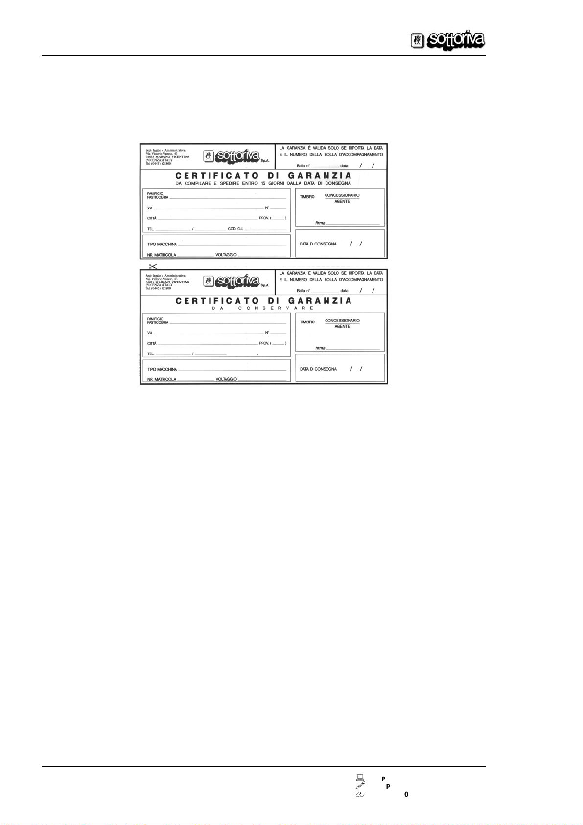
As a necessary condition for entitlement to warranty cover, the warranty
certificate (see facsimile below) must be sent off, duly completed, within
15
days
of the delivery date.
Moreover, if the applicant is unable to show the copy of the certificate kept
by the customer, the warranty may be considered as annulled.

VELA 90-130/1-160/1 -
Code: 3529.0
084.01
Rev. 0
dated 1
9/07/2004
Arc. 43-I
PT
0704
PP
0704
MC
0704
Technical Assistance Service
Tel. (+39) 0445.595.111
5
1.3 User instructions and precautions
The manufacturer declines all responsibility for any injury to persons or
animals or damage to objects resulting from the failure to observe any of the
previous or following information and instructions on the use or maintenance
of the machine:
z
DO NOT USE
the equipment for any purposes and/or loads different to
those stated by the manufacturer;
z
EVERY DAY, CHECK
the safety devices, oil level and general state of the
equipment;
z
EVERY DAY
clean the equipment thoroughly;
z
TAKE ALL THE NECESSARY PRECAUTIONS
andsafety measureswhen
loading, adjusting, changing parts or carrying out repair or maintenance
workon themachine,to make sure thatthemachine orany partsof it arenot
accidentally started up by other persons;
z
DO NOT TAMPER WITH
the guards and safety devices on the machine;
z
DO NOT REMOVE
the guards and safety devices on the machine unless
actually necessary for work purposes and without adopting the measures
designedtoreducetherisktothe minimum possible,asdescribedfullyand
frequently in this manual;
z
PUT BACK
all the guards and safety devices as soon as the reason for
their temporarily removal no longer exists;
z
OBSERVE THE FOLLOWING REGULATIONS
regarding workplace
safety and procedures:
-
regulations on safety notices and warnings as stated in DD.PP.RR.27/4/55,
n° 547 and n° 524 of date 8/6/82 and in D. Lgs 493/96 for Italy,orequivalent
regulations in the country where the machine is used;
-
European directives concerning workplace safety as stated in 89/391/CEE,
89/654/CEE, 89/655/EEC, 89/656/EEC, 90/269/EEC, 90/270/EEC,
90/394/EEC, 90/679/EEC, 95/63/EEC;
-
European directives concerning individualprotection measures as stated in
89/656/EEC and 89/686/EEC;
-
European directives on the environment, with special regard to
91/156
/EEC
concerning waste disposal,
91/689
/EEC on the disposalof dangerous waste
and 75/439/EEC on the disposal of used oils.
z
INFORM ALL PERSONNEL
of the specific hazards present in the
workplace.

Rev. 0
dated 1
9/07/2004
VELA 90-130/1-160/1 -
Code: 3529.0
084.01
6
Technical Assistance Service
Tel. (+39) 0445.595.111
PT
0704
PP
0704
MC
0704
Arc. 43-I
Photo 1
Fig. 1
1
2
3
4
5
6
8
7
9
2
0
46810 12 1416
20
18 2
0
46810 12 1416
20
18
1
3
2
5
7
8
6
9
4
VELA 90-130/1-160/1 -
Code: 3529.0
084.01
Rev. 0
dated 1
9/07/2004
Arc. 43-II
PT
0704
PP
0704
MC
0704
Technical Assistance Service
Tel. (+39) 0445.595.111
7
2. Descriptive manual
2.1 Foreword
Kneading Machine mod.
VELA 90-130/1-160/1
(see
Photo 1
on page 8) is a
machine for blending ingredients, generally water, flour, yeast and salt with
other secondary ingredients, and their mixture until a homogeneous dough
is produced for subsequent processing and cooking.
Any use for purposes other than those stated above may damage mechanical
components and/or endanger the safety of the machine operator.
2.2 Description
The machine consists in (see
Photo 1
):
1) a rigid structure
ref. 1
Photo 1
containing moving parts for the kneading
tool and tank;
2) a rotating tank
ref. 2
Photo 1
containing ingredients to be kneaded;
3) a kneading tool, to mix and knead the ingredients creating the shape of a
lengthened spiral.
4) An electrical control board
ref. 6
Photo 1
.
The control panel
ref. 4
Photo 1
, fitted to the front of the kneading tool carrier,
includes (see
Fig. 1
on page 8):
-
Start pushbutton
ref. 1
Fig. 1
, for 1st speed (slow);
-
start pushbutton
ref. 2
Fig. 1
, for the 2nd speed (fast);
-
a switch
ref. 4
Fig. 1
with three positions for tank start in either direction for
rotation;
-
an emergency stop button
ref. 3
Fig. 1
;
-
a large pushbutton
ref. 6
Fig. 1
for emergency shut-down;
-
a white warning light
ref. 5
Fig. 1
showing voltage feed;
-
a manually set timer with memory of set timefor slow operation
ref. 7
Fig. 1
;
-
a manually set timer with memory of set timefor fast operation
ref. 8
Fig. 1
;
-
a 3-position switch
ref. 9
Fig. 1
for impulse operation oftank,when the acci-
dent prevention guard is open.
The main switch is located on the electrical panel
ref. 8
Photo 1
.

Rev. 0
dated 1
9/07/2004
VELA 90-130/1-160/1 -
Code: 3529.0
084.01
8
Technical Assistance Service
Tel. (+39) 0445.595.111
PT
0704
PP
0704
MC
0704
Arc. 43-II
Photo 2
Fig. 2
2.3 Machine plate
In
Fig. 2
showing the machine plate and in
Photo 2
where it is fitted on the
machine with rivets or screws; it is aluminium with puched and silk screen
printed indelible lettering.
C.M. SOTTORIVA S.p.A.
Via Vittorio Veneto, 63
36035 MARANO VICENTINO
(Vicenza) - ITALY
Tel. (+39) 0445.595.111
Fax (+39) 0445.595.155
email:sottoriva@sottoriva.com
P.I. 00768890246
Mod.
n°
V
XXX
Hz
XX
kW
XX
VELA 90 (VELA 130/1-160/1)
XXXXXX
A
XX 3 AC + (N) + T
Mass kg
200_
VELA 90-130/1-160/1 -
Code: 3529.0
084.01
Rev. 0
dated 1
9/07/2004
Arc. 43-II
PT
0704
PP
0704
MC
0704
Technical Assistance Service
Tel. (+39) 0445.595.111
9
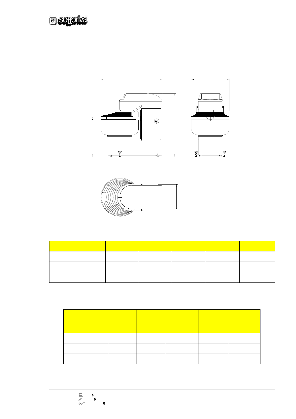
2.4 Overall dimensions and other data
With reference to showing overall dimensions in table 1, motor power
ratings and other data in table 2. (*) for a water/flour ratio of 55/100 for flour
with W=200 and P/L = 0.3.
Fig. 3
Table 1
Table 2
AC
B
D
E
MACHINE
A
B
C
D
E
VELA 90
1174
1296
738
819
530
VELA 130/1
1271
1296
833
963
530
VELA 160/1
1392
1415
929
938
590
MACHINE
mod.
Total
mass
Kg
Bowl power
kW
1st speed 2nd speed
Coil
power
kW
Kneading
capacity
kg (*)
VELA 90
405
0.6
1.1
2 / 3.7
90
VELA 130/1
435
0.6
1.1
2 / 4.7
130
VELA 160/1
660
0.75
1.5
3.7 / 5.9
160
Rev. 0
dated 1
9/07/2004
VELA 90-130/1-160/1 -
Code: 3529.0
084.01
10
Technical Assistance Service
Tel. (+39) 0445.595.111
PT
0704
PP
0704
MC
0704
Arc. 43-II
Footnote
This page has been left blank intentionally!
VELA 90-130/1-160/1 -
Code: 3529.0
084.01
Rev. 0
dated 1
9/07/2004
Arc. 43-III
PT
0704
PP
0704
MC
0704
Technical Assistance Service
Tel. (+39) 0445.595.111
11
3. Operation and installation
manual
3.1 Foreword
In compliance with European Community Directive no. 98/37/EEC, and for
the purposes of this manual, the following definitions are used:
1)
"Danger area"
, any area inside or near a machine which might be
dangerous for a bystander.
2)
"Bystander"
, any person entirely or partly situated in a danger area.
3)
"Operator"
, the person or persons installing, running, adjusting,
cleaning, repairing, transporting or performing maintenance work on a
machine.
3.2 Getting the workplace ready
If used for production (including cooking) of bakery products, the workplace
must meet the following requirements:
z
it musthave spaces wide enough to allow the bulkiestparts of the machine
to pass;
z
it must be built in compliance with current regulations;
z
it must be fitted with an electrical system complying with current regula-
tions,inparticulartheearthconnectionsystemand electricalcontrolboard
which must be protected against overload currents and short circuiting.
The rated power of the machine is shown on the machine plate. Electrical
plant must be properly installed throughout, maintained regular and regu-
larlyinspectedby trained electricians issuingcertificates of"good practice"
for all jobs carried out, guaranteeing compliance with current norms.

Rev. 0
dated 1
9/07/2004
VELA 90-130/1-160/1 -
Code: 3529.0
084.01
12
Technical Assistance Service
Tel. (+39) 0445.595.111
PT
0704
PP
0704
MC
0704
Arc. 43-III
3.3 Hoisting and transportation
To move the machine, it must be lifted as follows:
-
thread a lifting cable under the head, where the head meets the column, as
shown in
Fig. 4
on page 14
and secure as shown in
Fig. 4
to a hoisting
mechanism (crane, bridge crane, hoist, etc.). Place felt cloth between the
hoisting cable and the part of the machine under the head. Place a wood
shim of 70-80 mm thickness betweeen the side of the machine head and
the hoiting cable in order not to damage the paint finish or structure; lift the
machine gradually without any abrupt pulls.
Raising and lowering the machine must be a gradual process to avoid the
build up of kinetic energy which the braking system could not over-ride.
Given the considerable mass of the machine, before pushing it on its wheel
mounts, make sure no-one is standing behind or near the machine, since
impact could cause serious injury.
Fig. 4
Caution!
Before lifting the machine make sure that the cables are strong
enough to bear the load, and thatthe hoisting device has the suitable
capacityon the basis of the arrangementof the cables. In all cases,
equipment used for lifting must comply with current laws and regu-
lations.

VELA 90-130/1-160/1 -
Code: 3529.0
084.01
Rev. 0
dated 1
9/07/2004
Arc. 43-III
PT
0704
PP
0704
MC
0704
Technical Assistance Service
Tel. (+39) 0445.595.111
13
3.4 Assembly and installation
3.4.1
Installation precautions
The machine should be placed on the ground at the point shown in par. 3.3.
The machine must be lowered onto its supporting platform as gently as
possible in order to avoid damaging either the machine itself or the floor.
The machine should be moved on its wheels by pushing it to the new site
(see precautions above). When the machine is properly located, secure the
legs to the ground
ref. 9
Photo 1
on page 8
by using the knobs
ref. 7
Photo 1
to avoid excessive movements during the kneading process.
3.4.2
Instructions for the electrician
The electrician carrying out the installation must be skilled in this type of
work, properly trained and fully informed of the technical contents and
norms relating to the work, and of the standards of good practice.
The machine must be connected to the bakery's electrical plant in full
compliance with currents norms and regulations on the basis of the machine
specifications given in this manual; the machine is supplied with a CEI20-22
lead and EEC type plug (with the number of poles specified on the machine
plate) for connection to the electricity supply. Use the earth connection
system properly, without running the earth wire along gas or water pipes or
other metal structures not intended for earthing.
The power supply lead must be kept well clear of heated or moving parts.
The cable must not interfere with the movement of people or objects inside
the bakery.
3.5 Start-up
Trained personnel are not required to start up or operate the machine
(whereas properly trained personnel are required for some maintenance
operations; see para
4.1
), although all personnel starting up and operating
the machine must have read this manual from cover to cover and thoroughly
understood its contents.
Caution
Make sure that the mains voltage is the same as the voltage clearly
marked on the machine plate par. 2.3).

Rev. 0
dated 1
9/07/2004
VELA 90-130/1-160/1 -
Code: 3529.0
084.01
14
Technical Assistance Service
Tel. (+39) 0445.595.111
PT
0704
PP
0704
MC
0704
Arc. 43-III
After placing and securing the machine in its final location, carry out the
following important control operations in the given sequence:
1) check the mains voltage against the voltage shown on the machine plate
(seepar. 2.3)correspondstothelaboratoryvoltage;ifthevoltageisincorrect,
do not make electrical connections under any circumstances. Contact the
supplier or manufacturer immediately.
2) Make sure the machine rotates in the right direction; to do this, after
plugging in, carry out the following procedures:
-
switch the main switch
ref. 8
Photo 1
on page 8 to position 1;
-
set the minimum time on the timer
ref. 7
Fig. 1
on page 8;
-
press the start button for the 1st speed
ref. 1
Fig. 1
;
From the front of the machine, as shown in
Photo 2
on page 10
, the spiral
tool must rotate clockwise.
If this is not the case switch off, using the pushbutton
ref. 3
Fig. 1
; then switch
the main switch
ref. 8
Photo 1
from position 1 to position 0, unplug, unscrew
the plug as shown in the figure and invert the black and brown wires.
If the connection is three-phase + neutral + earth, there are two black wires.
In this case, either black wire may be switched over with the brown wire; if the
cable is three-phase + earth there is only one black wire so there is no
problem in switching over the wires.
Close the plug with the screws, as shown in the above illustration, and plug
back into the mains socket.
Re-check, repeating the sequence given at point 2. of this paragraph.
Rotation should now be clockwise.
Caution!
Never disconnect the yellow-green (earth) and/or blue wires or
change their positions.

VELA 90-130/1-160/1 -
Code: 3529.0
084.01
Rev. 0
dated 1
9/07/2004
Arc. 43-III
PT
0704
PP
0704
MC
0704
Technical Assistance Service
Tel. (+39) 0445.595.111
15
Caution
Unauthorised alteration or replacement of one or more parts or units
on the machine, or the use of accessories, tools or wearing parts dif-
ferent to the manufacturer's recommendations, may endanger the
safety of the machine operator or other persons close to the
machine. In all such cases, the manufacturer shall not be liable in
criminal or civil law for injury to persons and/or damage to objects
arising from unauthorised actions.
Footnote
After about 50 hours operation following initial installation, carry out
maintenance operations by tightening belts as described below.
par. 4.3.
Rev. 0
dated 1
9/07/2004
VELA 90-130/1-160/1 -
Code: 3529.0
084.01
16
Technical Assistance Service
Tel. (+39) 0445.595.111
PT
0704
PP
0704
MC
0704
Arc. 43-III
3.6 Operation
z
In
Photo 2
on page 10
shows the normal operator position; the position
should be occupied only for brief moments.
1) Feed into the tank
ref. 2
Photo 1
on page 8
all ingredients to be kneaded,
without exceeding the total mass specified in
Table 2
on page 11.
For this purpose, since the specific weightof flour is much less than water, the
capacity of the tank was designed on the basis of a water/flour ratio of 0.55,
loading the flour first, then the water (causing the flour to gain in density and
lose volume).
2) Switch the main switch
ref. 8
Photo 1
to position 1; the warning light
ref. 5
Fig. 1
on page 8 will come on;
3) Lower the accident-prevention guard
ref. 3
Photo 1
if raised, since in the
raised position the machine will not start).
4) Set timers
ref. 7 and 8
Fig. 1
torequiredkneadingtimesforslow and quick
blending.
5) Press the pushbutton
ref. 1
Fig. 1
for low speed start-up leaving the tool
enough time to "bind" the ingredients.
6) At the same time, switch the switch
ref. 4
Fig. 1
to the right-hand position
to rotate the tank clockwise, or to the left-hand position to rotate the tank
anticlockwise; the movement can be inverted or stopped (switch position 0)
at any time.
After the set time
ref. 7
Fig. 1
, the machine will automartically switch to the
fast cycle, for the set time
ref. 8
Fig. 1
.
Caution!
At the beginning of kneading operations, before the flour has absor-
bed much water and is still in the form of a powder, it is sensible prac-
tice to use the kneading tool at slow speed for 2 minutes to prevent
flour becoming air-borne and getting into the lungs, which, after len-
gthy periods of exposure, is dangerous for the health.
VELA 90-130/1-160/1 -
Code: 3529.0
084.01
Rev. 0
dated 1
9/07/2004
Arc. 43-III
PT
0704
PP
0704
MC
0704
Technical Assistance Service
Tel. (+39) 0445.595.111
17
7) Press the pushbutton
ref. 2
Fig. 1
to start up the machine directly at the
fast speed (this should not be done if there is still unmixed flour in the tank,
as specified above) or to skip from slow to fast speed at any moment.
8) When the set times for the two cycles have been reached, the tool
automatically shuts down.
9) Activating any of the safety devices or pressing the emergency stop
ref. 6
Fig. 1
, (or by means of the accident-prevention guard
ref. 3
Photo 1
on page
8), moving parts come to a stand still very quickly.
To prevent wear to the electrical emergency devices,
do not use emergency
shut-downs if it is possible to switch off normally
ref. 3
Fig. 1
.
Emergency devices should be used only to prevent dangerous situations
from arising or in dangerous situations (i.e. only in emergencies).
Remove the kneaded materials from the tank manually, in large provisional
portions, using a plastic paddle arm (never use steel paddles or scrapers).
10) Refill the tank with ingredients for the next operation.

Rev. 0
dated 1
9/07/2004
VELA 90-130/1-160/1 -
Code: 3529.0
084.01
18
Technical Assistance Service
Tel. (+39) 0445.595.111
PT
0704
PP
0704
MC
0704
Arc. 43-III
Footnote
This page has been left blank intentionally!

VELA 90-130/1-160/1 -
Code: 3529.0
084.01
Rev. 0
dated 1
9/07/2004
Arc. 43-IV
PT
0704
PP
0704
MC
0704
Technical Assistance Service
Tel. (+39) 0445.595.111
19
4. Maintenance manual
4.1 Foreword
All tasks which can be performed safely without specific training are defined
as "routine maintenance". All operations described par. 4.2 and par. 4.3 are
parts of routine maintenance.
Routine maintenance
as described in paragraphs
4.1
,
4.2
and
4.3
and
where specifically specified in this manual
may be carried out by the
machine operator provided he/she follows instructions to the letter
.
All operations are considered "extraordinary maintenenace" and must be
carried out by trained personnel
or, wherever specified in this manual
,
only
by personnel employed by the manufacturer
.
The manufacturer's telephone number is given at the foot of each page of
this manual; the fax number and internet address are given on the cover.
4.2 Daily maintenance
z
Cleanthemachinecarefullypayingspecialattentiontothepartswhichcome
into contact with food, such as the inside of the tank and the kneading tool
(see also par.
4.8
).
Do not use metal scapers or brushes, only soft plastic cleaning materials.
z
Check the efficiency of the accident-prevention devices.
(See the safety manual, chapter
5
).
4.3 Monthly maintenance
Check the belt tension and wear, and, if necessary replace. Replace for the
slightest wear or damage to the rubber.
Caution
THE MAIN SWITCH ref. 8
Photo 1
on page 8
MUST BE SWITCHED TO THE 0
POSITION OR THE MACHINE UNPLUGGED BEFORE CARRYING OUT ANY
CLEANING OR MAINTENANCE OPERATIONS ON THE MACHINE.
This manual suits for next models
1
Table of contents


