Soulsby Oscitron User manual

IMPORTANT SAFETY INSTRUCTIONS
•Read all the instructions before use.
•Do not position the module in direct sunlight or in areas
subject to heat, moisture, dust, cold or vibration.
•Clean the module with a damp cloth while switched off. Do not
use solvents or abrasive cleaners.
•Do not apply excessive force to any of the switches and knobs.
•The module is capable of producing audio levels that could
cause hearing loss. Do not plug headphones directly into the
audio output of the module. It is Eurorack voltage, which is
substantially higher than headphone voltage. If you experience
ringing in your ears after use, consult an audiologist.
•The EEPROM that stores patches has a life of 100,000
write/erase cycles. You may find it becomes unreliable after
this. The FRAM that stores user waves has a life of 100 trillion
write/erase cycles.
•THE POWER CABLE MUST BE CONNECTED WITH THE RED
IDENT FACING DOWN.
•Do not attempt to service the module. Contact Soulsby
Synthesizers if your Oscitron stops working.
qÜ~åâë=qçW=
Justin Owen (Abstract Data), Oli Horton (DREAMTRAK), James Weiner,
Steve Dawson, Neil Kagan and anyone else who has provided me with
information, advice and their time!

1
Introduction
Thank you for purchasing the Oscitron by Soulsby Synthesizers. We feel
certain that it will provide you with a whole world of new sounds and
creativity.
The controls have been designed to be intuitive and there are no complex
menu systems or sequences of button presses. The Oscitron is hackable
which means that completely different audio engines can be easily
uploaded to it via an FTDI cable and PC or Mac. This means that you have
effectively purchased an ever-growing number of modules, rather than
just the one!
The first section of this manual provides you with all the information for
basic operation of the Oscitron. The next chapters go through each
feature in detail. Following that there is an audio engine system diagram
and tables of certain sound parameters.
Oscitron parameters such as function names or physical connections are
highlighted in red.
Please take time to visit soulsbysynths.com where you can find more
information, including the latest news and downloads.
Specification
Inputs: 2x 0-5V 1V/Oct, 3x 0-5V CV, 1x 5V clock, 1x -/+5V audio, all 100kΩ
Outputs: 1x -/+5V audio output 1kΩ
Power Requirements: +/-12V via 10-pin IDC connector
Current Draw: +12V: 130mA approx., -12V: 70mA approx., +5V: 0mA
Width: 14HP Depth: 26mm from back panel, including IDC connector
Contents: Oscitron, 4x 10mm M3 screws, 4x 10mm M2.5 screws, 16-pin to
10-pin IDC cable, Quick Ref card, manual

2
Contents
Connections................................................................................................................. 3!
Basic Operation .........................................................................................................5!
Overview.................................................................................................................................... 5!
Function and Value Dials.................................................................................................. 5!
Inputs and Output..................................................................................................................7!
Functions .....................................................................................................................11!
Waveform Select.................................................................................................................. 11!
Audio Engine Resolution ................................................................................................. 11!
Coarse Frequency.............................................................................................................. 12!
Quantizer Scale.....................................................................................................................13!
Minimum Sample Length .............................................................................................. 14!
Filter Type............................................................................................................................... 14!
Wave Crusher....................................................................................................................... 16!
Load/Save Patch ..................................................................................................................17!
Inputs............................................................................................................................ 18!
Freq............................................................................................................................................ 18!
Pulse W.................................................................................................................................... 18!
Filt Freq ................................................................................................................................... 18!
Filter Res..................................................................................................................................19!
Phaser .......................................................................................................................................19!
Clock...........................................................................................................................................19!
Input............................................................................................................................................19!
Output ........................................................................................................................... 19!
Hacking....................................................................................................................... 20!
System Diagram ..................................................................................................... 21!
Audio Waveforms.................................................................................................. 22!
Quantize Scales...................................................................................................... 23!
Filter Types...............................................................................................................24!
Clock Input Global Settings.............................................................................. 25!
Wave Crusher Presets........................................................................................ 26!

3
Connections
cêçåí=
Function
dial
Value
knob
Value
dial
1V/Oct input 0-5V
Software driven tune knob
1V/Oct input 0-5V
Software driven tune knob
CV input 0-5V
Hardware 0-5V bias knob
CV input 0-5V
Hardware 0-5V bias knob
CV input 0-5V
Hardware 0-5V bias knob
0-5V clock input (also
can take CV)
-5 - +5V
audio input
-5 - +5V
audio output
Function
knob

4
_~Åâ=
10 pin
power IDC
RED
FTDI header
BLACK
ICSP header
(not used)

5
Basic Operation
lîÉêîáÉï=
The Oscitron is an 8-bit wavetable oscillator, with an audio engine
architecture based on the Atmegatron MIDI desktop synth.
It has some major differences from the Atmegatron that add features that
make it more suitable for Eurorack users. Many parameters are
controllable via CV inputs and there is an audio input for sampling User
Waveforms.
8-bit means that the sound is calculated digitally using 8-bit values
(integer numbers between 0 and 255). This is how home computers
worked in the 1980s and the Oscitron excels at creating these kinds of
sounds. However the processor is far more powerful than those in 80s
home computers, so it is packed with features never possible in that era.
Control of the Oscitron can be divided into the following areas:
cìåÅíáçå=~åÇ=s~äìÉ=aá~äë=
pÉäÉÅíáåÖ=ÑìåÅíáçåë=~åÇ=ëÉííáåÖ=î~äìÉë=
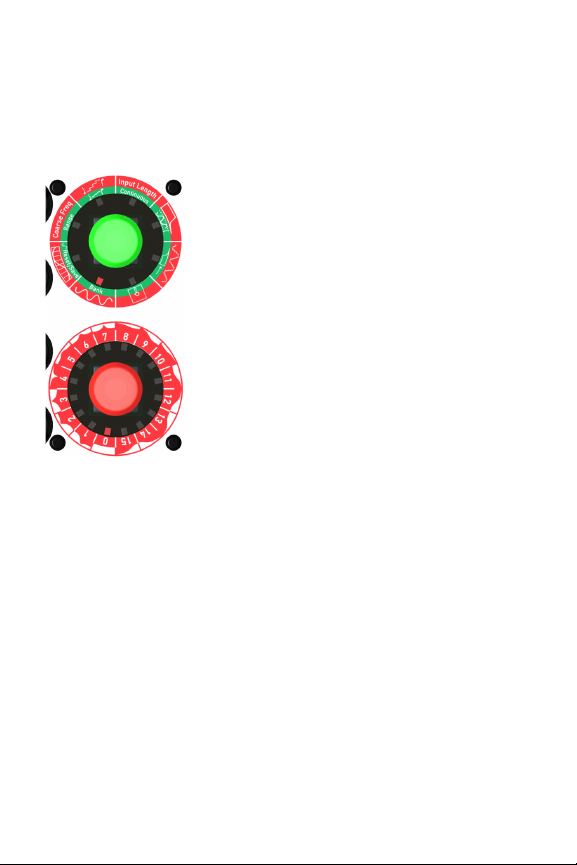
The function dial is on the top and the value dial is
on the bottom. By looking at the position of the lit
red LED and the corresponding symbol on the
dial, you can see what the current function is and
its value.
In this example, the function is set to Filter Type
and the value is set to 9(low shelf filter) as shown
by the outer ring on the value dial.
To change the Filter Type, turn the value knob
and the circular LED will change position. For
example if you want to change the Filter Type to a
low pass filter (LPF), turn the knob until the LED
next to 1on the inner dial is lit. There is a symbol
representing a low pass filter on the outer ring of
Function dial
Value dial
6
the value dial.
The full list of filter types and their corresponding symbols can be found
on page 24.
RÉÇ=~åÇ=ÖêÉÉå=ãçÇÉë=
The function knob can be pushed in and when
you do this, it changes from glowing red to green
(and vice versa). Each function on the function
dial has a green mode, which is activated by
briefly pushing the knob (< 2 secs).
For example turn the function knob so that
Waveform Select is highlighted. Listen to the
output. Now press the knob on the function dial,
so it glows green. You will hear that the sound
changes. This is because you are now in the
green bank of waveforms. If you turn the value
dial you can hear all the different waveforms in
the green bank.
däçÄ~ä=ëÉííáåÖ=ãçÇÉ=
Some functions also have an associated global setting. Pressing and
holding the Function knob when the relevant function is selected can
access these. After 2 seconds it will flash and turn yellow. The value of
the global function can then be selected with the Value knob. This value is
stored in EEPROM and is global to all patches (sounds), not just the
current one. A short press of the Function knob will leave the global
setting mode and the knobs and dials will return to their normal values.
iç~ÇáåÖ=~åÇ=ë~îáåÖ=é~íÅÜÉë=
To load or save a sound, turn the function knob to the load/save symbol (it
looks like a 5¼” floppy disk!)
To load a sound, turn the value knob to the patch number you require,
then briefly press the function knob.
To save a sound, turn the value knob to the patch number you want to

7
save over, and then hold the function knob down for at least 2 seconds.
The knob will flash when it is finished. The previous patch will be lost.
See page 17 for more information.
fåéìíë=~åÇ=lìíéìí=
The Oscitron has 2 1V/Oct inputs. There is an associated tune knob that
adjusts the parameter in software.
There are 3 CV inputs each with an offset knob. The offset knob adds a 0-
5V bias and can also be used to manually set the relevant parameter
when no input is connected.
There is a Clock input that triggers the waveform sampling of the audio
Input by default. However this input has many other options which are
described on page 19.
The Audio Input is used to sample User Waveforms into memory. The
Output is a standard Eurorack voltage (-5 to +5V) audio output.
t~îÉÑçêã=p~ãéäáåÖ=
The examples 1-4 overleaf show how the Oscitron can sample
waveforms via the audio input. Sampling is initiated by either pressing
the Value knob or by a pulse at the Clock input. Sampling starts and stops
when the incoming audio crosses 0V whilst rising from a negative to
positive voltage (known as a “zero crossing”).
The Input Length parameter sets the minimum number of samples to
store and can be used to eliminate erroneous waveforms captured
because of noise around 0V or to capture more complex timbres with
multiple zero crossings.
The state of the waveform sampling is shown by the colour of the Value
knob. This is shown in the examples.
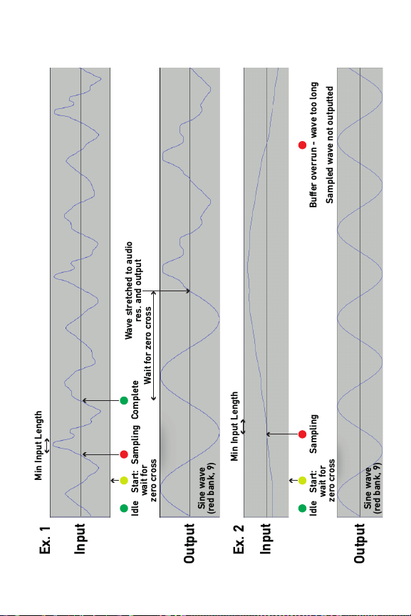
Example 1: páåÖäÉ=ï~îÉÑçêã=ë~ãéäáåÖ. Initially the waveform is set
to sine wave (red bank 9). This just demonstrates the output sound before
sampling. Sampling is initiated (value knob turns yellow). It starts writing
to the sample buffer when a zero crossing is detected at the input (value
knob turns red). It passes the Input Length value, which is low (e.g. 0= 4
samples). It stops when another zero crossing is detected at the input

8
(value knob turns green). The stored waveform is stretched to the
current audio engine resolution (see page 11) and outputted after a zero
crossing at the output. This is at the pitch defined by the oscillator
frequency parameters (1V/Oct input, fine & coarse tune, range).
Example 2: _ìÑÑÉê=çîÉêêìå. The maximum buffer length for sampling
is 256 samples. If the incoming waveform does not cross 0V before
reaching the end of the 256 sample buffer, it will abort the capture and
the value knob will remain red.
Example 3: eáÖÜÉê=î~äìÉ=Ñçê=fåéìí=iÉåÖíÜ. As example 1, but 2
wave cycles are stored because the minimum input length hasn’t been
reached once the first cycle is complete and this allows a more complex
timbre to be sampled. The stored waveform is still stretched to the audio
engine resolution and will therefore sound at twice the pitch of a single
cycle waveform (because 2 cycles are stored rather than 1). The values for
Input Length are below.
Input Length
Value
Minimum waveform
samples
0
4
1
16
2
64
3
128
4
192
5
224
6
240
7
252
Example 4: `çåíáåìçìë=ë~ãéäáåÖ=ãçÇÉ. As example 1, but sampling
restarts as soon as the previous sampled wave is outputted. This creates
a vocoder-style effect, although the actual process has nothing to do with
a vocoder. The Input Length is still changeable and creates variations in
timbre.
9
Input
Input
Ex. 1
Ex. 2
Idle Start:
wait for
zero cross
Sampling Complete
Output
Output
Idle Start:
wait for
zero cross
Sampling Buffer overrun - wave too long
Sampled wave not outputted
Min Input Length
Min Input Length
Wait for zero cross
Sine wave
(red bank, 9)
Sine wave
(red bank, 9)
Wave stretched to audio
res. and output

10
Min Input Length
Wave stretched to
audio res. & output
Input
Input
Ex. 3
Ex. 4
Idle Start:
wait for
zero cross
Sampling Keep
sampling
Complete
Output
Output
Min Input Length
Wait
Sine wave
(red bank, 9)
Start: wait zero cross
Output stretched wave Start
Output
Idle Start:
wait for
zero cross
Sampling Sampling
Complete Start
Output
Wait Wait Wait
Sine wave
(red bank, 9)

11
Functions
=t~îÉÑçêã=pÉäÉÅí=
There are 32 waveforms to choose from, 16 in red mode and 16 in green
mode. The full list of waveforms can be found on page 22.
=_~åâ=pÉäÉÅí=
Press the Function knob to toggle between the red and green bank of
waveforms.
RÉëÉí=~ää=rëÉê=t~îÉë=
To reset all User Waves back to the factory presets, hold the Function
knob until it flashes while the Value knob is held down
=^ìÇáç=båÖáåÉ=RÉëçäìíáçå=
One of the key differences between the Oscitron and the Atmegatron that
its sound is based on, is its ability to change the resolution of the audio
engine. The resolution of the Atmegatron is locked at 32 sample
waveforms. The Oscitron can be set to 16, 32, 64 and 128 sample
waveforms (value = 0,1,2,3respectively). It is important to note that these
resolutions apply to all stages of the audio chain (filter, phaser, wave
crusher etc), not just the oscillator output. The higher resolutions produce
more complex timbres, lower resolutions are more “gritty”.
=rëÉê=t~îÉ=RÉëÉí=L=p~îÉ=
A User Wave sampled via the audio Input can overwrite any of the 32
preset waveforms. See page 7 for info on how to sample a waveform. To
save a User Wave press and hold the Function knob until it flashes.
Please note that it will overwrite the currently selected waveform, the
value of which can be viewed by setting the function dial to Waveform
Select.

12
To reset the currently selected waveform back to the factory preset,
press the Function knob for a short time (< 2 secs). Setting the Function
dial to Waveform Select and incrementing then decrementing the Value
knob can restore the User Wave. To save the factory preset: press and
hold the Function knob until it flashes, as detailed above. After this, the
User Wave can no longer be restored.
=`ç~êëÉ=cêÉèìÉåÅó=
This sets the coarse frequency of the oscillator. The oscillator frequency
is set by the sum of the 1V/Oct input, the coarse and fine frequencies and
the range. The coarse frequency is in 4 semitone steps. When coarse = 9,
fine = 0, range = red (bottom) and the 1V/Oct input = 3.75V (A4-440Hz
using Doepfer MIDI to CV converter), the output will be A4-440Hz.
=R~åÖÉ=
Press the Function knob to toggle between oscillator frequency ranges.
When the Function knob is red, the frequency is set to the bottom half of
the range (equivalent to MIDI notes 0-64). When it is green it sets the
frequency to the top half (equivalent to MIDI notes 65-127).
NsLlÅí=fåéìí=`~äáÄê~íáçå=
The Freq and Filter Freqinputs can be calibrated for greater accuracy.
The inputs are calibrated before shipping, so this shouldn’t normally be
necessary.
To calibrate an input set the value dial to one of the following values and
send the relevant input the required voltage shown overleaf:

13
Value dial
Input
Calib Voltage
MIDI note equiv
0
Freq
1.25V
D#2-77.78Hz
1
Freq
3.75V
A4-440Hz
2
Filter Freq
1.25V
D#2-77.78Hz
3
Filter Freq
3.75V
A4-440Hz
Then press and hold the Function knob until it flashes, whilst holding the
value knob. Make sure both the low and high voltages are calibrated.
=nì~åíáòÉê=pÅ~äÉ=
The frequency of the oscillator can be quantized to a given scale. When
the Quantize scale = 0, the quantizer is bypassed. When it is active the
oscillator frequency is rounded up or down to the nearest note in the
scale. The scales are listed on page 23.
=mçêí~ãÉåíç=
Portamento (or glide) is the time it takes for the oscillator to change from
one frequency to another. The portamento values range from 0= 0 secs
(i.e. portamento off) to 15 = 6.5 secs. This time is fixed and is not
proportional to the change in frequency.
Press the Function knob to toggle between Portamento and Quantizer.
When it is red the quantizer is active and when it is green the portamento
is active.
nì~åíáòÉ=hÉó=
This is a global setting that sets the key of the quantizer. When the value
= 0the key is C (the chord is dependant on scale). This increases in
semitone steps to 11 where the key is B. See page 6 for more info on
global modes.

14
=jáåáãìã=p~ãéäÉ=iÉåÖíÜ=
This function is relevant when creating a User Wave via the audio Input.
Once sampling has started (when the input crosses through 0V from a
negative to positive value), it will only stop sampling when there is
another zero crossing and the total samples in the buffer is greater than
the value set for this function. This value ranges from 4 samples when
Input Length = 0to 252 samples when Input Length = 7. See page 7 for
full list. The sample buffer size is 256 samples maximum.
Lower values of Input Length will create more granular sounds. Higher
values will capture more complex timbres, but buffer overruns are more
likely.
=`çåíáåìçìë=p~ãéäÉ=jçÇÉ=
Press the Function knob to turn Continuous Sample Mode on and off.
Continuous Sample Mode is the same as normal waveform sampling,
apart from rather than performing the sampling routine once, it restarts
as soon as the process has completed. It is active when the Function knob
is green. A more detailed explanation of the process is on page 7.
`äçÅâ=fåéìí=aÉëíáå~íáçå=
By default the Clock input triggers Input sampling when it receives a
clock pulse. However this input is incredibly versatile and can be used to
control virtually any parameter of the Oscitron. It can also receive 0-5V
CV inputs as well as clock pulses. The routing of this input is stored as a
global setting. See page 6 for information on global settings and page 25
for the full list of parameters controllable by the Clock input.
=cáäíÉê=qóéÉ=
There are 15 filter types to choose from. Setting the value knob to 0will
turn off the filter. By shaping the harmonic content of the sound, it can
make the sound brighter or duller. The full list of filters can be found on
page 23.

15
The Filter Resonance control doesn’t affect the sound with some filter
types. This is the case with filter types 12 to 15. This is because the
algorithms for Butterworth and Bessel filters do not require a resonance
parameter.
If you are used to using analogue synthesizers you will notice that the
filters on the Oscitron sound a bit different, particularly at low cutoff
values. This is partly to do with the sound being calculated in 8-bit and
partly to do with the way the waveform is updated.
Changing the Audio Engine Resolution can dramatically alter the sound of
the filter. Higher resolutions allow for more accurate filtering. Lower
resolutions produce interesting “Chiptune” effects.
=cáäíÉê=kçêã~äáëÉ=jçÇÉ=
Press the Function knob to turn normalise mode on and off.
When Normalise mode is off (Function knob = red), the filter will distort
with certain filter settings, particularly when the resonance is high. This is
because the waveform is stored at maximum amplitude and there is no
headroom (which a 32-bit or 64-bit synth would traditionally have).
When Normalise mode is on (function knob is green), the waveform
amplitude is attenuated to 25% before filtering. This allows some
headroom, so that the filter doesn’t distort as easily. The waveform is then
normalised at the output of the filter (hence the name).
^äíÉêå~íáîÉ=fåéìí=_ÉÜ~îáçìê=
The Pulse Width and Phaser inputs can be set to control alternative
parameters, namely attenuators for the Freq and Filter Freq inputs. The
attenuation is done in software. It is worth noting that it only provides
attenuation and no bias. To convert a bipolar signal into a unipolar one
suitable for Oscitron inputs, a Soulsby Synthesizers Uni-Five module
should be used (or equivalent). The offset knobs for Pulse Width and
Phaser can be used to set the attenuation without any need for an
external CV source.

16
Value dial
Alternative behaviour
0
Off
1
Pulse Width input becomes Freq input attenuation
2
Phaser becomes Filter Freq input attenuation
3
Both 1and 2
=t~îÉ=`êìëÜÉê=
The Wave Crusher allows the resolution of the waveform to be reduced. It
can do this in two ways: reducing the bit depth of the waveform and
reducing the sample rate of the waveform. If the waveform were plotted
on a graph or viewed on an oscilloscope, changing the bit depth would
alter the resolution vertically. Changing the sample rate would alter the
resolution horizontally. The symbol for the Wave Crusher demonstrates
this process on a sine wave.
There are 15 useful combinations of bit depth and sample rate reduction
in the Oscitron. See page 26 for a list of them. When the value knob is at
0, the Wave Crusher is off.
It is worth noting that the Wave Crusher works differently to a bit crusher
effect commonly used in audio software. The Wave Crusher only affects
the waveform and not the overall output of the synthesizer (as would
happen with a bit crusher). This means that the decrease in resolution of
sample rate isn’t fixed, but is a division of the current frequency of the
oscillator.
=mêÉJcáäíÉê=jçÇÉ=
Press the Function knob to turn pre-filter mode on and off. When pre-
filter mode is off (function knob is red), the waveform is processed
through the Wave Crusher after the phaser and before distortion.
When pre-filter mode is on (function knob is green), the waveform is
processed through the Wave Crusher after the pulse width modulator and
before the filter. See the system diagram on page 21 for a visual depiction

17
of this. The Wave Crusher will sound more aggressive with pre-filter
mode off.
=iç~ÇLp~îÉ=m~íÅÜ=
The Oscitron has 16 memory locations to store patches (sounds).
To load a patch, set the function dial to Load/Save Patch and set the value
dial to the patch number that is to be loaded. Then briefly press the
function knob.
To save a patch, set the function dial to Load/Save Patch and set the value
dial to the patch number that is to be overwritten. Then hold the function
knob for 2 seconds until it flashes, signifying that it has saved. The
previous patch at this memory location will be lost.
18
Inputs
cêÉè=
This is a 1V/Oct input to control the frequency of the oscillator. It responds
to a voltage range between 0V and 5V. Inputting audio frequency signals
will not harm the Oscitron, but the standard Oscitron software will not
generate typical FM tones. This input is calibrated to achieve greater
accuracy. See page 12 for more information.
The Fine knob allows the oscillator to be offset by up to +4 semitones.
See page 12 for setting the coarse frequency of the oscillator. Please note
that when the Quantizer is on, the Fine knob may appear to have no effect
if quantizing to scales with intervals greater than 4 semitones.
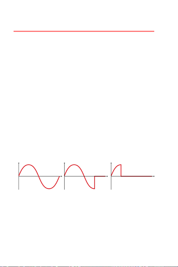
mìäëÉ=t=
This is a 5V CV input that controls the Pulse Width of the waveform. The
Offset knob adds a 0-5V bias to the CV input.
Many classic analogue synthesizers have a pulse width parameter.
Traditionally this controls the mark/space ratio of a square wave. The
Oscitron’s pulse width parameter works in a similar way and is the ratio
of sound to silence within the waveform. The diagram below shows Pulse
Width applied to a sine wave at 0%, 25% and 75%.
cáäí=cêÉè=
This is a 1V/Oct input to control the cutoff frequency of the filter. It
responds to a voltage range between 0V and 5V. This input is calibrated to
achieve greater accuracy. See page 12 for more information.
The Coarse knob sets the offset of filter cutoff frequency with respect to
the oscillator frequency (i.e. the filter has pitch tracking). The overall cutoff

19
frequency is the sum of the 1V/Oct input, the coarse offset and the
oscillator frequency.
cáäíÉê=RÉë=
This is a 5V CV input that controls the resonance of the filter. The Offset
knob adds a 0-5V bias to the CV input.
mÜ~ëÉê=
This is a 5V CV input that controls the delay time of the Phaser. The Offset
knob adds a 0-5V bias to the CV input.
The Phaser effect adds a delayed copy of the waveform to the output.
When the delay time is at the minimum value, the phase delay is 0º and
the effect is bypassed. When it is at the maximum value, the delay is 360º.
A slow sine wave LFO input will produce the classic phaser effect.
`äçÅâ=
Normally this is a 5V clock input. This input can also except 5V CV signals
dependant on a global setting – see page 14 for more information.
When the Clock Destination global setting = 0 (it is set to this on first
boot), a clock pulse will trigger the audio Input sampling. This is
equivalent to pressing the Value knob.
fåéìí=
-5V to +5V audio input. This is the audio Input for sampling. Voltages
outside of this range will be clipped. Page 7 details the audio sampling
process.
Output
The audio output is a Eurorack standard -5V to +5V output.
Table of contents
Other Soulsby Synthesizer manuals


