Sound Devices A20-Nexus User manual
A20-Nexus
8-, 12-, and 16-Channel, True-Diversity Receiver
with SpectraBand Technology
User Guide v1.00

Table of Contents
Welcome to the A20-Nexus 4
Key Features 4
SpectraBand 5
Digital Wireless Modulation 5
NexLink Wireless Transmitter Control 5
GainForward 5
Architectural Overview 7
Panel Views 8
Typical Setups 12
Quick Start 16
Powering 19
Navigating the A20-Nexus User Interface 21
Menus 28
RTSA (Real Time Spectrum Analyzer) 29
Scan Mode 32
TX List 33
RF Menu 34
Antenna RF Overload Indication 36
Audio Outputs 36
Timecode 39
Networking 40
System Menu 42
Quick Setup Menu 45
Nexus Web App 47
Updating Firmware 50
Accessories 51
A20-QuickDock for 8-Series 51
A20-Monarch Antenna 56
A20-Shelf 56
2.4 GHz Antenna Bracket Assembly Kit 56
Frequency Band Restrictions 58
Connector Pin Assignments 59
A20-Nexus User Guide
2


Welcome to the A20-Nexus
The A20-Nexus is an ultra-high performance, 8-, 12-, and 16-channel wireless microphone receiver in a compact ½-rack wide
chassis. It features 8 independent, true-diversity channels which can be expanded to 12 or 16 true-diversity channels via software
license. The A20-Nexus features NexLink, an innovative concept in wireless microphone receivers: full remote control of microphone
transmitters via an integrated, long distance RF link.
The A20-Nexus can be mounted in a standard 19-inch rack or easily placed remotely near the microphone transmitters due to its
ability to be powered by Power-over-Ethernet (PoE+), its Dante audio-over-IP, and built-in web server for control via phone, tablet, or
computer.
Additionally, the A20-Nexus can be docked to Sound Devices 833, 888, or Scorpio mixer-recorders using the A20-QuickDock
accessory, which provides convenient power, audio, and timecode connections with no additional cables. This accessory allows the
A20-Nexus to connect and disconnect from the 833, 888, or Scorpio in seconds with no tools, and be remote mounted when
desired.
Key Features
● 8-channel ultra-high-performance, true-diversity receivers in a ½ rack size (8.0” x 6.6” x 1.6”).
● Expandable to 12 or 16 channels via software license (coming soon).
● 470 MHz – 1525 MHz tuning range via SpectraBand Technology.
● NexLink: integrated, long distance remote control of all wireless transmitters
● Dante audio-over-IP of RF receiver audio.
● Flexible powering: via PoE+, DC input, 8-Series, or AC mains (with optional adapter).
● Web App control from browser on any computer, smartphone or tablet.
● Full remote operation capability: Power via PoE, audio via Dante, control via Web App.
● Dual DB-25 connectors for 16 channels of mic, line, or AES outputs.
● Convert 16 channels of Dante to analog & AES on DB25 connectors for sending IFB, VOG & more from mixer to set.
● Wide, 6.2” color OLED array with touch for control and monitoring.
● Integrated Real Time Spectrum Analyzer (RTSA) and scanning for intuitive frequency coordination.
● Optical Fiber Network option via SFP slot. SFP accepts a wide variety of modular network transceivers.
● A20-QuickDock allows docking and undocking in seconds from 8-Series mixer-recorders with no tools.
● Supports GainForward Architecture: No gain setting on the A20-Mini transmitter. Adjust gain at the receiver or mixer.
● 100% digital long-range modulation delivers the longest transmission distance of any digital system on the market.
● RF SAW filters for excellent rejection of interference from nearby IFB or camera hop transmitters.
● Excellent audio quality, full 10 Hz – 20 kHz audio bandwidth.
● BNC timecode input for auto timecode sync of transmitters over NexLink
● Front panel and rear panel BNC antenna inputs. Compatible with passive, bias-powered, and smart antennas.
● Cascade out option on rear BNCs for cascading multiple A20-Nexus units.
● Front-panel headphone output.
● USB-A port for thumb drives, keyboards, transmitter pairing, and timecode syncing. Supports USB hubs.
Our friendly and knowledgeable support team, based in the USA and the UK, is here for all your questions and comments.
A20-Nexus User Guide
4

SpectraBand
The A20-Nexus incorporates SpectraBand, a technology that enables the A20-Nexus to tune over a super wide range of 470-1525
MHz. Tuning within this range varies by country.
For instance:
In the USA, the available frequency ranges are:
●The entire UHF TV band (470-608 MHz)
●The 600 MHz guard band (614-616 MHz)
●The 600 MHz duplex gap (653-663 MHz)
●The 900 MHz ISM Band (902-928MHz)
●The 950 MHz STL Band (941.5-960 MHz)
●The 1.5 GHz AFTRCC band (1435-1525 MHz), with an appropriate license.
In the UK, the available frequency ranges are:
●The core UK UHF TV band (470-702 MHz)
●The 800 MHz duplex gap (823-832 MHz)
●The 800 MHz guard band (863-865 MHz)
●The DME bands (961-1015 MHz, 1045-1075 MHz, 1105-1154 MHz), with an appropriate license.
●The IMT band (1518-1525 MHz)
Please see https://www.sounddevices.com/frequency-tables/ for further detailed information on which frequency ranges are
available for each country.
Tuning Bands
SpectraBand’s 470-1525 MHz range is divided into multiple, tightly-filtered tuning bands. The sharp attenuation at either end of a
tuning band’s range significantly reduces out of band interference resulting in excellent range performance.
Digital Wireless Modulation
Long Range and Standard Modulation
The A20 wireless products offer two proprietary digital modulation schemes that provide unbeatable range, unrivaled audio quality,
and very low latency. Long Range or Standard modulation can be selected on a per-receiver-channel basis. Long Range modulation
has better sensitivity which results in better range. The modulation setting must match between the A20-Mini, A10-TX and the
A20-Nexus in order for the transmitted signal to be received and decoded.
Intermodulation Immunity
Because the A20 and A10 digital RF transmission is inherently resistant to intermodulation, multiple A10 and A20 Digital Wireless
systems can be used simultaneously on nearby adjacent frequencies without significant worry of intermodulation interference.
Systems can be used together when separated by at least 400 kHz. When operating in the 902-928 MHz Band, it is recommended
to separate channel frequencies by at least 1 MHz.
NexLink Wireless Transmitter Control
NexLink is a proprietary 2.4 GHz bidirectional wireless data link technology that allows multiple A20-Mini transmitters to be
controlled, monitored, and timecode synced from an A20-Nexus over long distance. NexLink is designed to offer robust and reliable
control over distances far exceeding that of the wireless audio transmission, even in the presence of Wi-Fi and Bluetooth
interference. An A20-Nexus can pair with up to 16 NexLinked transmitters at a time, while a single A20-Nexus channel can NexLink
with one transmitter at a time.
GainForward
The A20-Nexus supports the A20-Mini transmitter’s GainForward feature. GainForward eliminates the need to adjust microphone
preamplifier gain at the wireless transmitter. Audio levels from the transmitter are controlled either directly from the 8-Series (or any
other mixer) trim controls, or from the A20-Nexus receiver screen. If the talent speaks too softly or emotes too loudly after being
A20-Nexus User Guide
5

“wired” with the transmitter, simply adjust the transmitter gain with the mixer’s gain trim, instead of having to access the actual
transmitter. Read more about GainForward at: https://www.sounddevices.com/gainforward-explained/
When an A20-Nexus receiver channel is receiving signal from an A20-Mini transmitter, adjust the receiver channel’s gain, low cut,
and polarity from its associated 1RX view.
When the A20-Nexus is docked on an 8-Series, the Nexus’s gain, low cut, and polarity settings are bypassed and hidden. In this
case, adjust the 8-Series’ trim, low cut and polarity gain as necessary. See the 8-Series User Guides for more information.
A20-Nexus User Guide
6

Architectural Overview
The A20-Nexus takes a brand new approach to professional audio receiver design. The A20-Nexus combines several technologies
resulting in a very powerful and versatile product.The diagram below illustrates the architecture of the A20-Nexus.
The first thing to note about the architecture is that there are two entire signal paths. This performs the True Diversity reception
inherent in the design. This is a lavish proposition, as it doubles the circuitry, but it is absolutely the best way to perform spatial
diversity - superior to any type of antenna or phase diversity.
The first section that comes right after the receive antennas is the first SAW filter array. This pre-select filter is a key element of our
unique SpectraBand technology. It allows for a tuning range from 470 MHz - 1525 MHz which is divided into multiple, tightly-filtered
tuning bands. The extremely sharp attenuation at either end of a tuning band’s range significantly reduces unwanted interference
outside the selected tuning band resulting in excellent range performance. Tuning bands vary in width, but tend to be around 24
MHz wide.
Next is the Low-Noise Amplifier (LNA), which is one of the most important stages in the design. This section has been specially
designed for very low noise and high dynamic range, which results in long-range reception and high overload capability. This LNA
stage exhibits a noise figure of only 0.35 dB, one of the very best on the market currently.
This is followed by yet another SAW filter array. This array further attenuates out-of-band signals, ensuring reliable reception, and
greatly suppressing any image frequencies.
The Local Oscillator and Mixer perform the traditional function of a single downconversion superheterodyne radio. This section has
been meticulously designed and is the other key element of our unique SpectraBand technology. This section exhibits extremely low
phase noise and wide dynamic range to accurately downconvert the RF to a lower Intermediate Frequency (IF) for conversion into
the digital domain.
Before conversion into the digital domain, the signal passes through its final array of SAW filters, rejecting any extraneous energy
not wanted in the downconversion, as well as providing anti-aliasing before the Analog-to-Digital (A/D) converter. The A/D converter
is a wideband, extremely high dynamic range part which accurately captures 24 MHz of IF energy into a digital version of that signal.
The real magic of the entire A20-Nexus happens within the Field-Programmable Gate Array (FPGA). An FPGA is essentially a giant
custom, massively-parallel processor programmed in house. The FPGA can perform filtering, frequency conversion, and
demodulation in the digital domain which far exceeds anything that can be done via analog or traditional digital circuitry. The FPGA
can perform demodulation of 16 channels simultaneously. The FPGA also performs the True Diversity operation which not only
selects the best digital word from the two antennas but actually works at the bit level for additional range. The resultant audio signals
are then fed out of the FPGA to the various audio outputs.
A20-Nexus User Guide
7
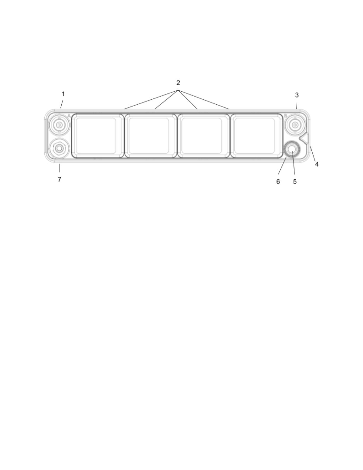
Panel Views
Front Panel
1 & 3: Antenna Connector A & B
BNC connectors, for connecting to active, passive, or smart antennas.
2: Touch Screens
Color OLED array for control and monitoring. The screens can be set to turn off after a period of inactivity from the Selection menu.
(Main Menu>System>Screensaver).
4: Triangle Button
● Press to power up. Press and hold to power down.
● When powered up, press to cycle through the current Receiver view, Main Menu, and RTSA. Backs out of sub-menus.
5: Headphone Knob
● Rotate to adjust headphone output level.
● Rotate to scroll through lists and select parameter values.
● Rotate to scroll frequency cursor or adjust horizontal/vertical zoom in RTSA/Scan view.
6: Multicolor Ring LED
● Solid blue when powering up
● Red when headphone output is clipping.
● Flashing orange when selected Sync Reference is not detected.
● Solid green when the front panel is locked out. See menu (Main Menu>System>Lockout Mode).
7: Headphone Output
3.5 mm connector
A20-Nexus User Guide
8
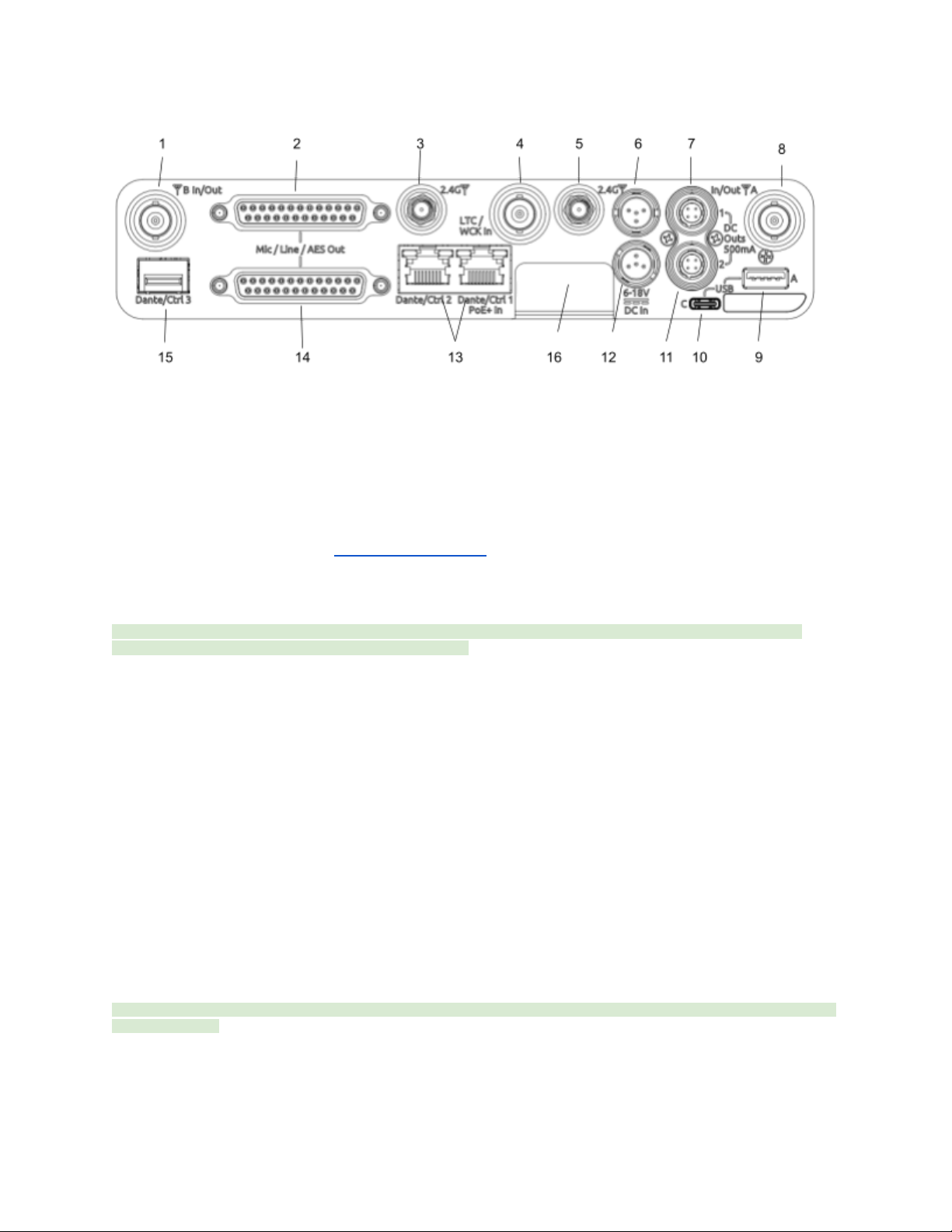
Rear Panel
1 & 8: Antenna Connector A & B Inputs / Cascade Outs
● BNC connectors for connecting active, passive, or smart antennas.
● Cascade outs for looping through the front panel antenna A & B inputs. Only available when front panel antennas are
selected in the (Main Menu>RF) menu. The cascade out passively splits the incoming signal, resulting in approximately
3.5 dB of loss. In some situations, additional antenna gain and/or amplification may be desirable to maintain excellent
range.
2 & 14: Top & Bottom D-Sub Audio Output Connectors
25-pin D-Sub connectors for outputting analog (mic/line level) or AES digital. See menu (Main Menu>Audio Output). Disabled when
mounted to an 8-Series via the expansion port. Note: the pin-out follows the AES59 standard. The analog output pin-out is different
from the AES digital output pin-out. See Connector Pin Assignments section for more information.
3 & 5: 2.4 GHz Antenna Connectors
Dual SMA-F ports for connecting 2.4 GHz SMA-M antennas for NexLink. Both antennas need to be connected.
Important: Only use the 2.4 GHz SMA-M antennas supplied with the A20-Nexus or equivalent. Do not use 2.4 GHz RP-SMA
antennas such as those used for the 8-Series bluetooth antenna.
4: LTC / Wordclock Input
BNC for connecting LTC or Wordclock input. Nexus auto-detects whether the signal is LTC or Wordclock including the associated
frame rate or sample rate. Disabled when mounted to an 8-Series via the expansion port.
6 & 12: DC Inputs
Dual TA4-M, 10-18V DC inputs. Highest voltage takes precedence. Disabled when docked to an 8-Series via the expansion port.
7 & 11: DC Outputs
Dual, 4-pin Hirose female DC outputs (500 mA max between both outputs) for powering IFB transmitters, camera hops, and other
low power peripherals. Disabled when docked to an 8-Series via the expansion port.
When powered via TA4, voltage is passed through from the DC input (10-18V). When powered via PoE+, DC Outputs supply 12V
DC.
9: USB-A Port
Multi-function USB-A port for:
● Pairing and syncing timecode to A20 transmitters. Connect the transmitter to Nexus using a USB-C to USB-A cable.
● Connecting a USB keyboard for naming channels, quick setup files and network. The USB keyboard is active whenever
the virtual keyboard screen is displayed.
● Mounting a USB thumb drive for updating firmware and loading/saving settings.
Tip: The USB-A port supports USB hubs so that multiple devices can be connected at the same time. Maximum power output of 2.5
Watts (5V, 500 mA)
10: USB-C Port
For factory use only.
A20-Nexus User Guide
9

13: Ethernet Ports 1 & 2
2x RJ45 ports for Dante and/or Control. Nexus can be powered via PoE+ (minimum 25W) via port 1. Dante is disabled when docked
to an 8-Series via the expansion port. Control remains enabled.
15: SFP Port
Accepts a wide variety of Small Form-factor Pluggable (SFP) modular network transceivers, including optical fiber options for
Ethernet Dante and/or Control connection. Dante is disabled when docked to an 8-Series via the expansion port. Control remains
enabled.
16: Factory Access Cover
Covers and protects the factory-use only ports.
Bottom Panel
1: Mounting Point
1 / 4”, 20 screw hole for mounting purposes.
2: Expansion Port
For docking A20-Nexus to an 8-Series mixer/recorder using the A20-QuickDock optional accessory.
The expansion port provides power from the 8-Series and passes the multichannel receiver digital audio signals from A20-Nexus to
the 8-Series. When docked on an 8-Series:
● The A20-Nexus and its NexLinked transmitters are controlled from the Nexus OLED touch screen user interface. The
8-Series interface is not used for control.
A20-Nexus User Guide
10

● A20-Nexus rear panel connectors are disabled apart from the antenna connectors, control network, and the USB-A port.
● The USB-A port has the following capabilities:
○ Pairing A20-Mini transmitters to the A20-Nexus by connecting a USB-C cable from the transmitter to the USB-A
port.
○ Attaching a USB keyboard for entering text directly (e.g. receiver channel names) into the A20-Nexus.
○ Mounting a USB thumb drive for updating A20-Nexus firmware and saving setup files.
○ Syncing 8-Series timecode to an A20-Mini from the A20-Nexus.
3: Screw holes for A20-QuickDock and A20-Shelf
Four screw holes for mounting the A20-Nexus to an A20-Shelf and A20-QuickDock
A20-Nexus User Guide
11

Typical Setups
The versatile A20-Nexus can be used in many types of setup and workflow. This section details just a few examples.
1. Bag Setup: Nexus docked to an 8-Series Mixer-Recorder
The A20-QuickDock accessory enables the A20-Nexus to be docked to an 8-Series mixer-recorder. The bottom panel incorporates
a multi-pin expansion port that connects power from the 8-Series and passes the multichannel receiver digital audio from A20-Nexus
to the 8-Series.
A20-Nexus User Guide
12

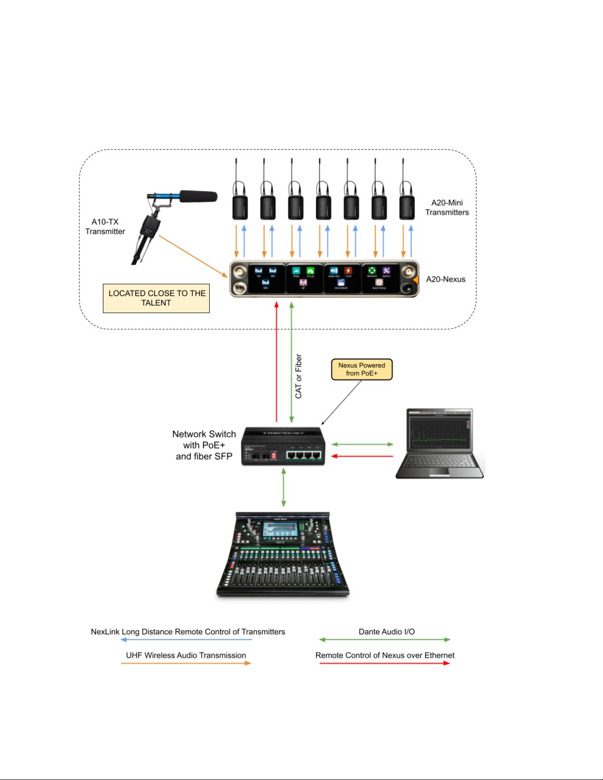
2. Remote Setup: Nexus located on set, close to talent
Remotely locating the A20-Nexus multichannel receiver close to talent significantly reduces the chance of RF dropouts since the
distance between those wearing the transmitters and the A20-Nexus receiver is minimized. A single CAT cable can be used to
transport Dante audio and remote control data between Nexus and the sound mixer. As well as sending Dante audio to the mixer,
the Nexus can also receive Dante audio back from the mixer, useful for distributing VoG and/or IFB feeds etc via its analog D-Sub
outputs. In this example, the Nexus Web App is running on a tablet and controlling the Nexus over Wi-Fi.
A20-Nexus User Guide
13
3. Remote Setup: Nexus located on set, close to talent, powered from PoE+
Similar to the previous setup, but with the Nexus being powered over PoE+. In this example, a computer is controlling Nexus via the
Web App and is also sending and receiving Dante to and from Nexus.
A20-Nexus User Guide
14

4. Cart Setup
A typical cart setup with Nexus. As well as sending Dante audio to the mixer, the Nexus can also send audio from its AES or Analog
D-Sub outputs. In this example, the Nexus Web App is running on a tablet and controlling the Nexus over Wi-Fi.
A20-Nexus User Guide
15

Quick Start
This Quick Start guide assumes that the A20-Nexus is being used as a standalone receiver.
1. Connect a 10-18V DC power source to either or both TA4-M DC inputs. Alternatively, connect PoE+ to Ethernet port 1.
2. Connect suitable passive, bias-powered, or smart antennas to either the front or rear BNC A and B antenna ports.
3. If using NexLink to control and monitor A20-Mini transmitters, connect 2.4 GHz antennas to both rear panel 2.4 GHz SMA
ports.
4. Connect required rear panel audio outputs (Analog, AES, and/or Dante) from Nexus to external devices.
5. Connect headphones to the front panel 3.5 mm headphone output.
6. Power Up. Press the front panel triangle button to power up. Press and hold to power down. When powered up for the
very first time, receiver channels 1-8 are displayed. This view is called the 8RX View. All RX channels will be Off.
8RX View
7. Press the triangle button to display the Main Menu.
8. Tap the System icon to enter the System menu.
9. Ensure Country is set to the country that you are in. The Country setting determines which Tuning Bands and RF
frequencies are legally unrestricted and available for selection in the A20-Nexus. If using A20-Mini transmitters, make sure
that the A20-Remote app they are paired to is also set to the same country.
Main Menu
10. Tap the RF icon in screen 2 to access the RF menu.
11. Select Front or Rear antennas by tapping the button at the bottom of screen 2. When ‘Rear’ is displayed, the rear
antennas are selected. When ‘Front’ is displayed, the front antennas are selected.
RF Menu
12. If the antennas require bias-power, tap the A and B antenna gear icons to display A and B antenna settings respectively
and set both their Power (Bias) settings to On.
A20-Nexus User Guide
16
Antenna Settings
The antenna icons will show a lightning bolt icon next to them when bias power is enabled.
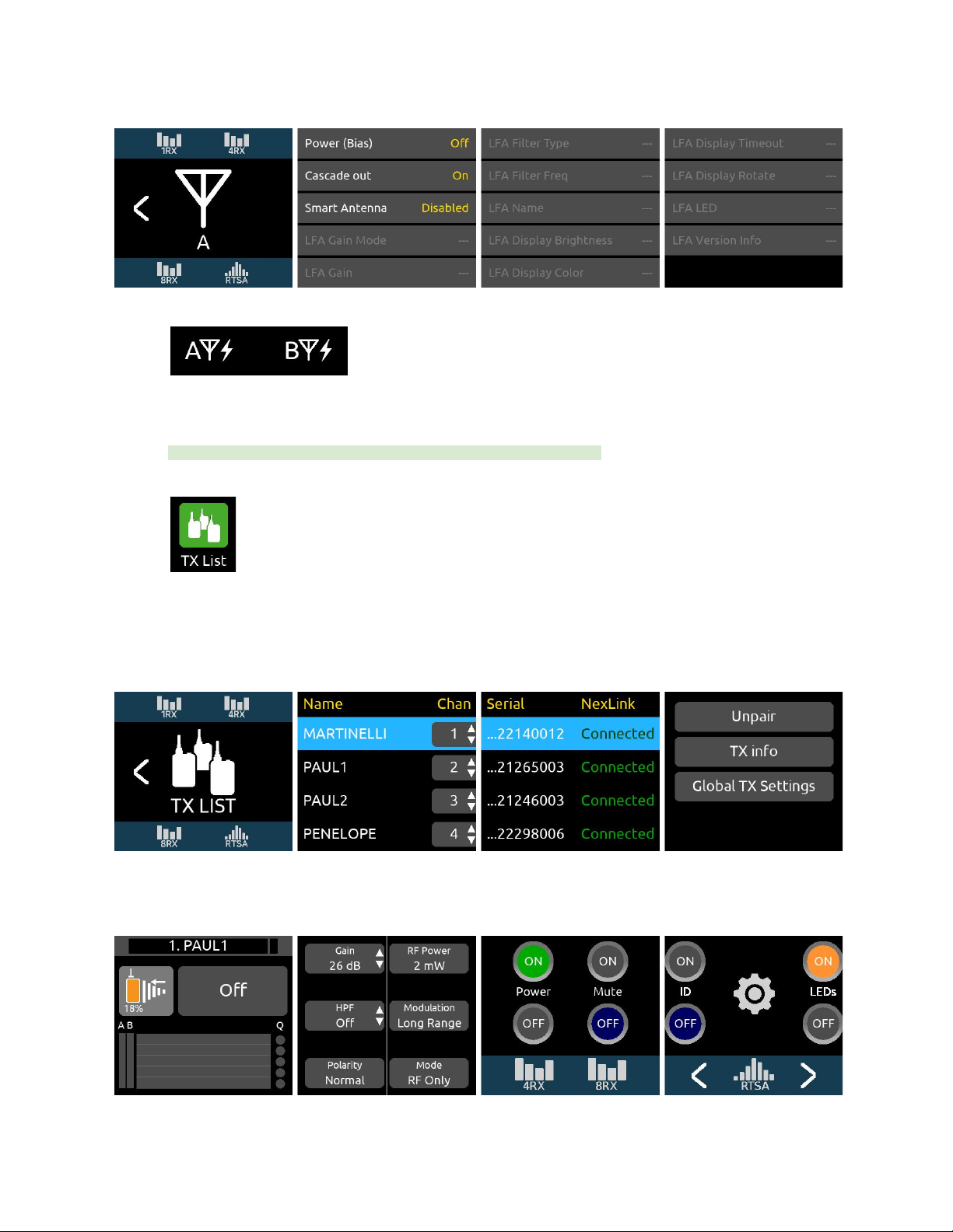
13. Pair and NexLink A20-Mini transmitters. Pairing is a process that adds A20-Mini transmitters to the A20-Nexus TX List.
The TX List is an inventory of available transmitters that can be selected for wireless remote-control via NexLink.
Note: A10-TX transmitters cannot be paired or NexLinked with the A20-Nexus.
From the Main Menu, tap the TX List icon.
To pair an A20-Mini transmitter, ensure it has a charged battery or batteries installed, then connect its USB-C port to the
A20-Nexus USB-A port. The A20 transmitter will appear in the TX List after a few seconds. The A20-Nexus will then
automatically establish a NexLink connection between the transmitter and the next available receiver channel. This can
take a minute or so. Once connection is established, ‘Connected’ is displayed in the TX List > NexLink column.
TX List
14. From the TX List, rotate the front panel knob to highlight a receiver channel, then press the knob to jump to its 1RX View
from which the receiver and its NexLinked transmitter can be configured and monitored.
1RX View
A20-Nexus User Guide
17
15. In the 1RX View, ensure the transmitter is well within range by checking that the 2.4 GHz NexLink signal strength indicator
in the leftmost screen shows good signal strength.
16. If the A20-Mini transmitter is not already on, tap the Power ON button in screen 3 of the 1RX View.
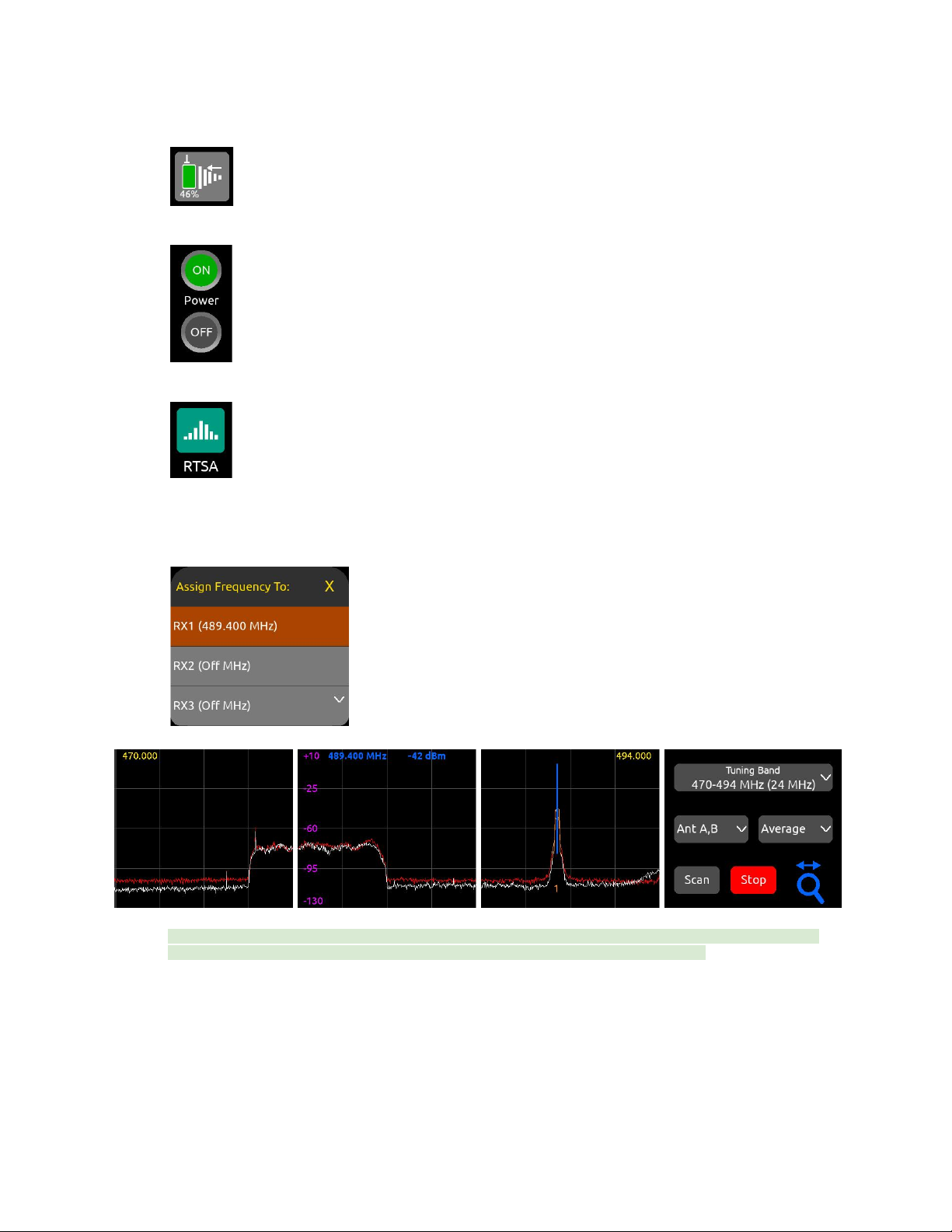
17. Press the triangle button to access the Main Menu, then tap the RTSA icon.
18. In the RTSA, rotate the HP knob (or tap the top half of the plot) to move the blue vertical frequency marker to a clean
frequency (i.e. where there is low background RF noise). Press the HP knob to display the ‘Assign Frequency To:’ list then
tap RX1 to assign the clean frequency to receiver channel 1. The frequency is automatically pushed to the transmitter and
its RF signal appears in the trace.
Tip: Before assigning frequencies, it is highly recommended to perform a scan of the local RF environment using Scan
Mode to identify and choose a clear Tuning Band. See RTSA > Scan Mode for further information.
19. Tap the orange ‘1’ below the transmitter signal to jump to the 1RX View for channel 1, tap the Gain button and rotate the
HP knob to bring up the gain until you see audio signal from the lav connected to the A20-Mini. Press the HP knob to
store the gain value.
20. Put your headphones on and listen. Rotate the HP knob clockwise to increase the HP gain.
Congratulations! You have your first wireless channel ready to go.
A20-Nexus User Guide
18
Powering
The A20-Nexus is powered from TA4 (10-18 VDC), PoE+, from the 8-Series (via expansion port), or via XL-WPTA4
AC mains adapter (purchased separately).
The headphone knob ring LED illuminates blue during power up, then goes out once fully booted.
When the Nexus is first powered on, the last accessed RX View is displayed.
Tip: Reducing A20-Nexus power consumption:
● Turn off unused receiver channels. See 1RX View.
● Disable Dante by setting Network > Port Configuration to Control Only, All Ports
●Where possible, power via TA-4 or the 8-Series. While PoE is a practical and convenient option for powering the
A20-Nexus remotely, it is slightly less efficient than straight DC. This is due to the finite efficiency of the PoE injector and
the internal PoE supply of the Nexus.
Powering when Nexus is operated standalone (not docked to an 8-Series)
Connect a 10-18 VDC power source (20 watt minimum) to the TA4 DC power inputs and/or PoE+ power source (30 watt minimum)
to ethernet port ‘Dante/Ctrl 1’. Connecting multiple power sources allows for redundancy since the A20-Nexus seamlessly switches
between power sources should one fail. The power source with highest voltage takes precedence and is displayed along with its
voltage beneath the Power menu icon in the Main Menu and in screen 1 of the Power menu.
● To turn Nexus on, press the triangle button or, with Power menu >‘Turn on when power is applied’ enabled, simply
connect a power source.
● To turn Nexus off, press and hold the triangle button until the ‘Powering down ..” progress bar completes.
Powering when Nexus is docked to an 8-Series
Connect power to the 8-Series. Power is supplied to the Nexus from the 8-Series expansion port.
Note: When docked, powering via the A20-Nexus TA4 or PoE+ power inputs is disabled.
Ensure that the 8-Series System Menu > Expansion Port is set to On.
● If Power menu >‘Turn on when power is applied’ is enabled, Nexus automatically powers on when the 8-Series is turned
on.
● If Power menu >‘Turn on when power is applied’ is disabled, turn on the 8-Series then press the triangle button to turn on
Nexus.
● To turn Nexus off but keep the 8-Series on, press and hold the triangle button until the ‘Powering down ..” progress bar
completes.
● To turn off both the 8-Series and Nexus, move the 8-Series power toggle switch to Off.
A20-Nexus User Guide
19

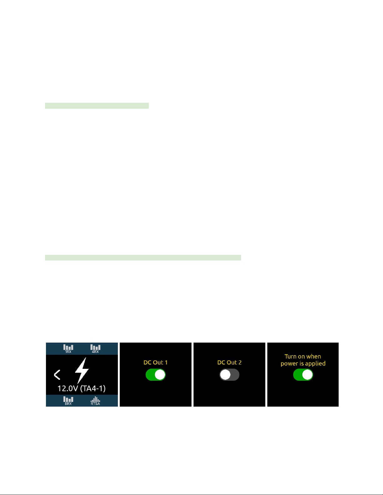
Power Outputs DC Out 1 and DC Out 2
When operated standalone and powered via TA4 DC inputs or PoE+, the A20-Nexus can provide power to peripherals via the two
4-pin Hirose DC Outputs (500 mA max between both outputs) on the rear panel. Enable or disable each DC Output from the Power
menu.
These can be used for powering IFB transmitters, camera hops, and other low power peripherals. When powered via TA4, voltage is
passed through from the DC input (10-18V). When powered via PoE+, DC Outputs supply 12V DC.
Note: When powered by the 8-Series, the DC1 and DC2 toggle switches are off and grayed out.
A20-Nexus User Guide
20
Other manuals for A20-Nexus
1
Table of contents
Other Sound Devices Receiver manuals


