Sound Devices A20-Nexus User manual

A20-Nexus Go
4-, 6-, and 8-Channel, True-Diversity Receiver
with SpectraBand Technology
User Guide v1.50

Table of Contents
Welcome to the A20-Nexus Go 3
Key Features 3
SpectraBand 4
Digital Wireless Modulation 4
NexLink Wireless Transmitter Control 4
GainForward 4
Architectural Overview 6
Panel Views 7
Typical Setup 10
Quick Start 11
Powering 14
Navigating the A20-Nexus Go User Interface 15
RX Views 17
Menus 26
RTSA (Real Time Spectrum Analyzer) 27
Scan Mode 30
AutoAssign 30
TX List 32
RF Menu 34
Antenna RF Overload Indication 35
Audio Outputs 36
Timecode 38
System Menu 39
Quick Setup Menu 42
Updating Firmware 44
Channel Expansion Licenses 44
Accessories 45
A20-QuickDock for 8-Series 45
A20-Monarch Antenna 50
A20-Shelf 50
A20-2.4G Ant+Mount 50
NexLink Status Alerts 52
Frequency Band Restrictions 53
Connector Pin Assignments 54
A20-Nexus Go Specifications 56
A20-Monarch Specifications 58
Note on RF Interference 59
Servicing the A20-Nexus Go 59
Warranty 59
Legal Notices 60
Declaration of Conformity 63
A20-Nexus Go User Guide
2

Welcome to the A20-Nexus Go
The A20-Nexus Go is an ultra-high performance, multichannel wireless microphone receiver in a compact ½-rack wide chassis. It
features 4 independent, true-diversity channels that can be expanded to 6 or 8 true-diversity channels via software license. The
A20-Nexus Go features NexLink, an innovative concept in wireless microphone receivers: full remote control of microphone
transmitters via an integrated, long-distance RF link.
The A20-Nexus Go is ideal for use in a portable bag setup or mounted in a standard 19-inch rack. Additionally, the A20-Nexus Go
can be docked to Sound Devices 833, 888, or Scorpio mixer-recorders using the A20-QuickDock accessory, which provides
convenient power, audio, and timecode connections with no additional cables. This accessory allows the A20-Nexus Go to connect
and disconnect from the 833, 888, or Scorpio in seconds with no tools.
Key Features
● 4-channel ultra-high-performance, true-diversity receivers in a ½ rack size (8.0” x 6.6” x 1.6”).
● Expandable to 6 or 8 channels via 2-channel expansion licenses.
● 169 MHz – 1525 MHz tuning range via SpectraBand Technology.
● NexLink: integrated, long-distance remote control of all wireless transmitters, including group power on/off.
● Integrated Real Time Spectrum Analyzer (RTSA) and scanning for intuitive frequency coordination.
● AutoAssign: automatic deployment of clean frequencies in seconds.
● Flexible powering: via DC input, 8-Series, or AC mains (with optional adapter).
● DB-25 connector for 8 channels of mic, line, or AES outputs.
● Wide, 6.2” color OLED array with touch for control and monitoring.
● A20-QuickDock allows docking and undocking in seconds from 8-Series mixer-recorders with no tools.
● Supports GainForward Architecture: No gain setting on the A20 transmitter. Adjust gain at the receiver or mixer.
● 100% digital long-range modulation delivers the longest transmission distance of any digital system on the market.
● RF SAW filters for excellent rejection of interference from nearby IFB or camera hop transmitters.
● Excellent audio quality, full 10 Hz – 20 kHz audio bandwidth.
● BNC timecode input for auto timecode sync of transmitters over NexLink.
● Front panel and rear panel BNC antenna inputs. Compatible with passive and bias-powered antennas.
● Supports control of the Wisycom LFA smart antenna.
● Cascade out option on rear BNCs for cascading multiple A20-Nexus Go units.
● USB-A port for thumb drives, keyboards, transmitter pairing, and timecode syncing. Supports USB hubs.
Our friendly and knowledgeable support team, based in the USA and the UK, is here for all your questions and comments.
A20-Nexus Go User Guide
3

SpectraBand
The A20-Nexus Go incorporates SpectraBand, a technology that enables the A20-Nexus Go to tune over a super wide range of
169-1525 MHz. Tuning within this range varies by country.
For instance:
In the USA, the available frequency ranges are:
●The VHF band (169-216 MHz)
●The entire UHF TV band (470-608 MHz)
●The 600 MHz guard band (614-616 MHz)
●The 600 MHz duplex gap (653-663 MHz)
●The 900 MHz ISM band (902-928MHz)
●The 950 MHz STL band (941.5-960 MHz)
●The 1.5 GHz AFTRCC band (1435-1525 MHz), with an appropriate license.
In the UK, the available frequency ranges are:
●The VHF band (173-210 MHz)
●The core UK UHF TV band (470-702 MHz)
●The 800 MHz duplex gap (823-832 MHz)
●The 800 MHz guard band (863-865 MHz)
●The DME bands (961-1015 MHz, 1045-1075 MHz, 1105-1154 MHz), with an appropriate license
●The IMT band (1518-1525 MHz)
Please see https://www.sounddevices.com/available-frequencies/ for further detailed information on which frequency ranges are
available for each country.
Tuning Bands
SpectraBand’s 169-1525 MHz range is divided into multiple, tightly-filtered tuning bands. The sharp attenuation at either end of a
tuning band’s range significantly reduces out-of-band interference resulting in excellent range performance.
Digital Wireless Modulation
Long Range and Standard Modulation
The A20 wireless products offer two proprietary digital modulation schemes that provide unbeatable range, unrivaled audio quality,
and very low latency. Long Range or Standard modulation can be selected on a per-receiver-channel basis. Long Range modulation
has better sensitivity which results in better range. The modulation setting must match among the A20 transmitters, A10-TX
transmitter and the A20-Nexus Go in order for the transmitted signal to be received and decoded.
Intermodulation Immunity
Because the A20 and A10 digital RF transmission is inherently resistant to intermodulation, multiple A10 and A20 Digital Wireless
systems can be used simultaneously on nearby adjacent frequencies without significant worry of intermodulation interference.
Systems can be used together when separated by at least 400 kHz. When operating in the 902-928 MHz Band, it is recommended
to separate channel frequencies by at least 1 MHz.
NexLink Wireless Transmitter Control
NexLink is a proprietary 2.4 GHz bidirectional wireless data link technology that allows multiple A20 transmitters to be controlled,
monitored, and timecode synced from an A20-Nexus Go over long distances. NexLink is designed to offer robust and reliable control
over distances far exceeding that of the wireless audio transmission, even in the presence of Wi-Fi and Bluetooth interference. An
A20-Nexus Go can pair with up to 64 NexLinked transmitters.
GainForward
The A20-Nexus Go supports the A20 transmitter’s GainForward feature. GainForward eliminates the need to adjust microphone
preamplifier gain at the wireless transmitter. Audio levels from the transmitter are controlled either directly from the 8-Series (or any
other mixer) trim controls, or from the A20-Nexus Go receiver screen. If the talent speaks too softly or emotes too loudly after being
A20-Nexus Go User Guide
4

“wired” with the transmitter, simply adjust the transmitter gain with the mixer’s gain trim, instead of having to access the actual
transmitter. Read more about GainForward at: https://www.sounddevices.com/gainforward-explained/
When an A20-Nexus Go receiver channel is receiving signal from an A20 transmitter, adjust the receiver channel’s gain, low cut,
and polarity from its associated 1RX view.
When the A20-Nexus Go is docked on an 8-Series, the Nexus receiver’s gain, low cut, and polarity settings are bypassed and
hidden. In this case, adjust the 8-Series’ trim, low cut and polarity gain as necessary. See the 8-Series User Guides for more
information.
A20-Nexus Go User Guide
5

Architectural Overview
The A20-Nexus Go takes a brand new approach to professional audio receiver design. The A20-Nexus Go combines several
technologies, resulting in a very powerful and versatile product.The diagram below illustrates the architecture of the A20-Nexus Go.
The first thing to note about the architecture is that there are two entire signal paths. This performs the True Diversity reception
inherent in the design. This is a lavish proposition, as it doubles the circuitry, but it is absolutely the best way to perform spatial
diversity - superior to any type of antenna or phase diversity.
The first section that comes right after the receive antennas is the first SAW filter array. This pre-select filter is a key element of our
unique SpectraBand technology. It allows for a tuning range from 169 MHz - 1525 MHz that is divided into multiple, tightly-filtered
tuning bands. The extremely sharp attenuation at either end of a tuning band’s range significantly reduces unwanted interference
outside the selected tuning band, resulting in excellent range performance. Tuning bands vary in width, but tend to be around 24
MHz wide.
Next is the Low-Noise Amplifier (LNA), which is one of the most important stages in the design. This section has been specially
designed for very low noise and high dynamic range, which results in long-range reception and high overload capability. This LNA
stage exhibits a noise figure of only 0.35 dB, one of the very best on the market currently.
This is followed by yet another SAW filter array. This array further attenuates out-of-band signals, ensuring reliable reception, and
greatly suppressing any image frequencies.
The Local Oscillator and Mixer perform the traditional function of a single downconversion superheterodyne radio. This section has
been meticulously designed and is the other key element of our unique SpectraBand technology. This section exhibits extremely low
phase noise and wide dynamic range to accurately downconvert the RF to a lower Intermediate Frequency (IF) for conversion into
the digital domain.
Before conversion into the digital domain, the signal passes through its final array of SAW filters, rejecting any extraneous energy
not wanted in the downconversion, as well as providing anti-aliasing before the Analog-to-Digital (A/D) converter. The A/D converter
is a wideband, extremely high dynamic range part that accurately captures 24 MHz of IF energy into a digital version of that signal.
The real magic of the entire A20-Nexus Go happens within the Field-Programmable Gate Array (FPGA). An FPGA is essentially a
giant custom, massively parallel processor programmed in house. The FPGA can perform filtering, frequency conversion, and
demodulation in the digital domain that far exceeds anything that can be done via analog or traditional digital circuitry. The FPGA
can perform demodulation of 16 channels simultaneously. The FPGA also performs the True Diversity operation that not only selects
the best digital word from the two antennas but actually works at the bit level for additional range. The resultant audio signals are
then fed out of the FPGA to the various audio outputs.
A20-Nexus Go User Guide
6
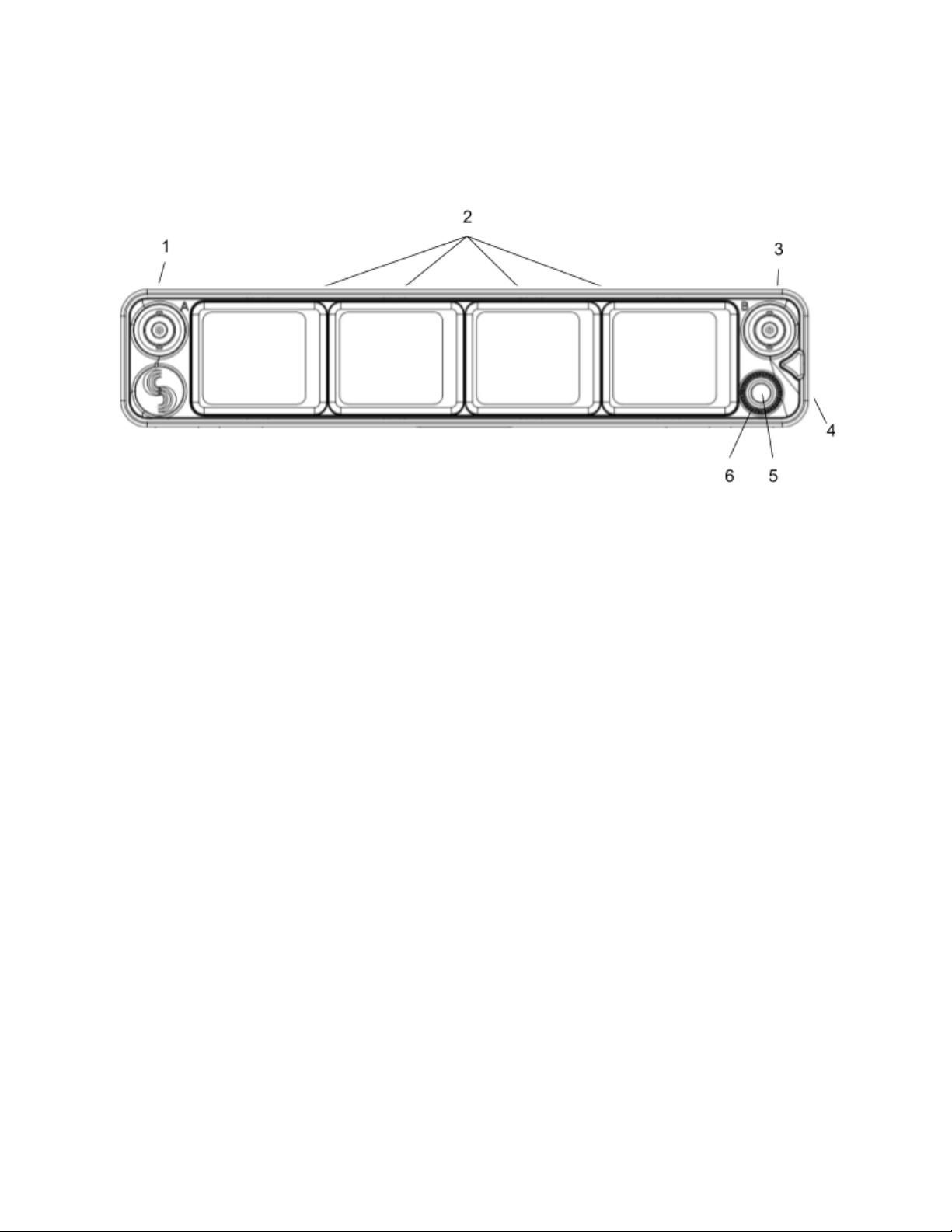
Panel Views
Front Panel
1 & 3: Antenna Connector A & B
BNC connectors, for connecting to active, passive, or smart antennas.
2: Touchscreens
Color OLED array for control and monitoring. The screens can be set to turn off after a period of inactivity from the Selection menu.
(Main Menu>System>Screensaver).
4: Triangle Button
● Press to power up. Press and hold to power down.
● When powered up, press to cycle through the current Receiver view, Main Menu, and RTSA. Backs out of sub-menus.
5: Control Knob
● Rotate to scroll through lists and select parameter values.
● Rotate to scroll frequency cursor or adjust horizontal/vertical zoom in RTSA/Scan view.
6: Multicolor Ring LED
● Solid blue when powering up
● Flashing orange when selected Sync Reference is not detected.
● Solid green when the front panel is locked out. See menu (Main Menu>System>Lockout Mode).
A20-Nexus Go User Guide
7

Rear Panel
1 & 8: Antenna Connector A & B Inputs / Cascade Outs
● BNC connectors for connecting active, passive, or smart antennas.
● Cascade outs for looping through the front panel antenna A & B inputs. Only available when front panel antennas are
selected in the (Main Menu>RF) menu. The cascade out passively splits the incoming signal, resulting in approximately
3.5 dB of loss. In some situations, additional antenna gain and/or amplification may be desirable to maintain excellent
range.
2: D-Sub Audio Output Connector
25-pin D-Sub connector for outputting analog (mic/line/guitar level) or AES digital. See menu (Main Menu>Audio Output). Disabled
when mounted to an 8-Series via the expansion port. Note: the pin-out follows the AES59 standard. The analog output pin-out is
different from the AES digital output pin-out. See Connector Pin Assignments section for more information.
3 & 5: 2.4 GHz Antenna Connectors
Dual SMA-F ports for connecting 2.4 GHz SMA-M antennas for NexLink. Both antennas need to be connected.
Important: Only use the 2.4 GHz SMA-M antennas supplied with the A20-Nexus Go or equivalent. Do not use 2.4 GHz RP-SMA
antennas such as those used for the 8-Series bluetooth antenna.
4: LTC / Word Clock Input
BNC for connecting LTC or Word Clock input. Nexus auto-detects whether the signal is LTC or Word Clock, including the associated
frame rate or sample rate. Disabled when mounted to an 8-Series via the expansion port.
6: DC Input
TA4-M, 10-18V DC input. Disabled when docked to an 8-Series via the expansion port.
7 & 11: DC Outputs
Dual, 4-pin Hirose female DC outputs (500 mA max between both outputs) for powering IFB transmitters, camera hops, and other
low-power peripherals. Disabled when docked to an 8-Series via the expansion port.
When powered via TA4, voltage is passed through from the DC input (10-18V).
9: USB-A Port
Multifunction USB-A port for:
● Pairing and syncing timecode to A20 transmitters. Connect the transmitter to A20-Nexus Go using a USB-C to USB-A
cable.
● Connecting a USB keyboard for naming channels, quick setup files, and network. The USB keyboard is active whenever
the virtual keyboard screen is displayed.
● Mounting a USB thumb drive for updating firmware and loading/saving settings.
Tip: The USB-A port supports USB hubs so that multiple devices can be connected at the same time. Maximum power output of 2.5
Watts (5V, 500 mA)
10: USB-C Port
For factory use only.
12: Card Slot
A20-Nexus Go User Guide
8

For factory-use only.
Bottom Panel
1: Mounting Point
1 / 4”-20 screw hole for mounting purposes.
2: Expansion Port
For docking A20-Nexus Go to an 8-Series mixer-recorder using the A20-QuickDock optional accessory.
The expansion port provides power from the 8-Series and passes the multichannel receiver’s digital audio signals from A20-Nexus
Go to the 8-Series. When docked on an 8-Series:
● The A20-Nexus Go and its NexLinked transmitters are controlled from the Nexus OLED touchscreen user interface. The
8-Series interface is not used for control.
● A20-Nexus Go rear panel connectors are disabled apart from the antenna connectors and the USB-A port.
● The USB-A port has the following capabilities:
○ Pairing A20 transmitters to the A20-Nexus Go by connecting a USB-C cable from the transmitter to the USB-A
port.
○ Attaching a USB keyboard for entering text directly (e.g. receiver channel names) into the A20-Nexus Go.
○ Mounting a USB thumb drive for updating A20-Nexus Go firmware and saving setup files.
○ Syncing 8-Series timecode to an A20 transmitter from the A20-Nexus Go.
3: Screw holes for A20-QuickDock and A20-Shelf
Four screw holes for mounting the A20-Nexus Go to an A20-Shelf and A20-QuickDock
A20-Nexus Go User Guide
9
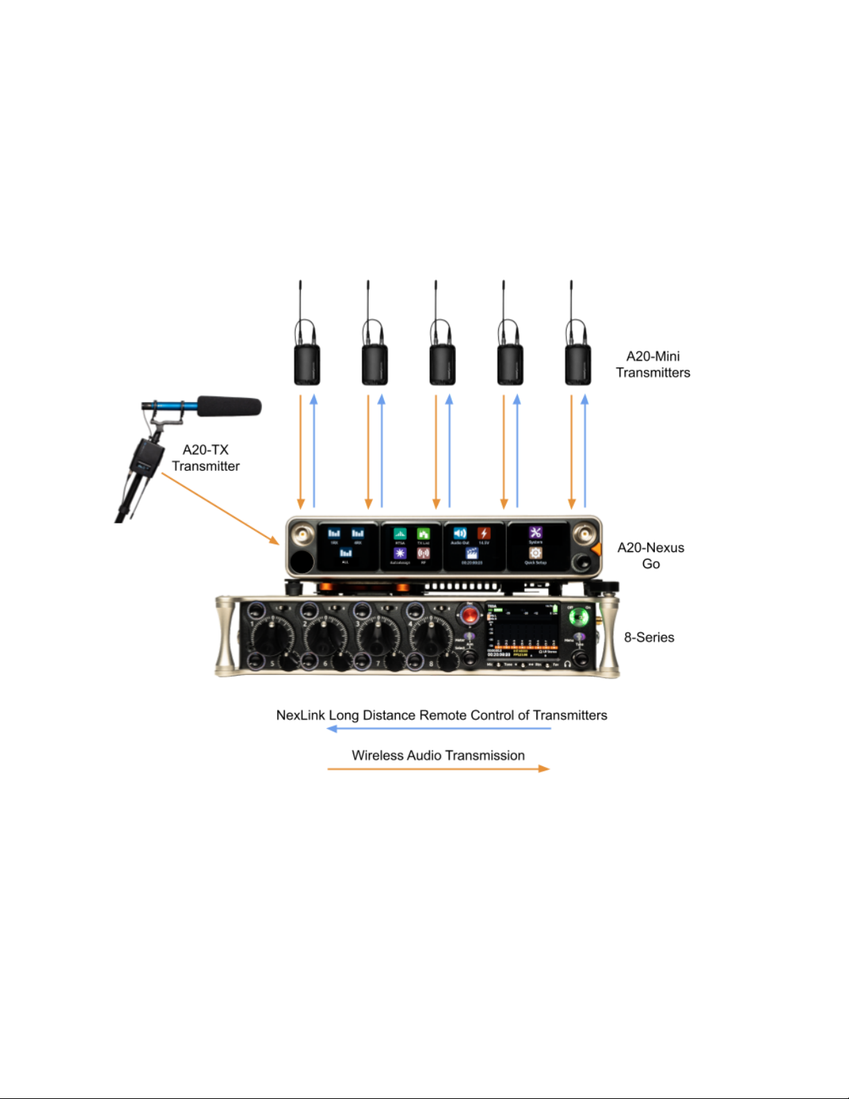
Typical Setup
The versatile A20-Nexus Go can be used in many types of setups and workflows. Here is an example with a 6-ch A20-Nexus Go
(one expansion license installed) docked to an 8-Series mixer-recorder. The A20-QuickDock accessory enables the A20-Nexus Go
to be docked to an 8-Series mixer-recorder. The bottom panel incorporates a multi-pin expansion port that connects power from the
8-Series and passes the multichannel receiver digital audio from A20-Nexus Go to the 8-Series.
A20-Nexus Go User Guide
10

Quick Start
This Quick Start guide assumes that the A20-Nexus Go is being used as a standalone receiver.
1. Connect a 10-18V DC power source to the TA4-M DC input.
2. Connect suitable passive, bias-powered, or smart antennas to either the front or rear BNC A and B antenna ports.
3. If using NexLink to control and monitor A20 transmitters, connect 2.4 GHz antennas to both rear panel 2.4 GHz SMA
ports.
4. Connect required rear panel audio outputs (Analog, AES) from the A20-Nexus Go to external devices.
5. Power Up. Press the front panel triangle button to power up. Press and hold to power down. When powered up for the
very first time, receiver channels 1-4 are displayed. This view is called the ALL View (or 4RX View when expansion
licenses are installed). All RX channels default to Off.
ALL View
6. Press the triangle button to display the Main Menu.
7. Tap the System icon to enter the System menu.
8. Ensure Country is set to the country that you are in. The Country setting determines which Tuning Bands and RF
frequencies are legally unrestricted and available for selection in the A20-Nexus Go. If using A20 transmitters, make sure
that the A20-Remote app they are paired to is also set to the same country.
Main Menu
9. Tap the RF icon in screen 2 to access the RF menu.
10. Select Front or Rear antennas by tapping the button at the bottom of screen 2. When ‘Rear’ is displayed, the rear
antennas are selected. When ‘Front’ is displayed, the front antennas are selected.
RF Menu
11. If the antennas require bias-power, tap the A and B antenna gear icons to display A and B antenna settings respectively
and set both their Power (Bias) settings to On.
A20-Nexus Go User Guide
11

Antenna Settings
The antenna icons will show a lightning bolt icon next to them when bias power is enabled.
12. Pair and NexLink A20 transmitters. Pairing is a process that adds A20 transmitters to the A20-Nexus Go TX List. The
TX List is an inventory of available transmitters that can be selected for wireless remote-control (via NexLink) and
assigned to receiver channels.
Note: A10-TX transmitters cannot be paired or NexLinked with the A20-Nexus Go.
From the Main Menu, tap the TX List icon.
To pair an A20 transmitter, ensure it has a charged battery or batteries installed, then connect its USB-C port to the
A20-Nexus Go USB-A port. The A20 transmitter will appear on the TX List after a few seconds. The A20-Nexus Go will
then automatically establish a NexLink connection between the transmitter and the next available receiver channel. This
can take up to a minute or so. Once connection is established, the NexLink RSSI icon is displayed in the TX List >
NexLink column.
TX List
13. From the TX List, rotate the Control knob to highlight a receiver channel, then press the knob to jump to its 1RX View from
which the receiver and its NexLinked transmitter can be configured and monitored.
1RX View
A20-Nexus Go User Guide
12
14. In the 1RX View, ensure the transmitter is within NexLink range by checking that the NexLink RSSI indicator on the
leftmost screen shows good signal strength.
15. If the A20 transmitter is not already on, tap the Power ON button on screen 3 of the 1RX View.
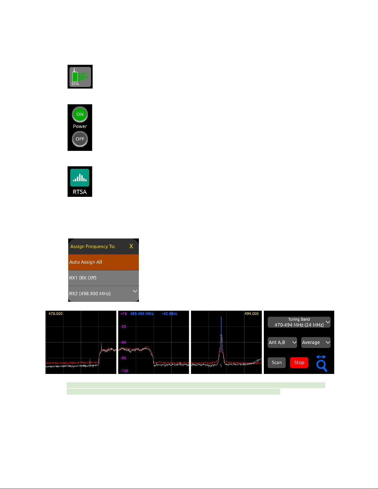
16. Press the triangle button to access the Main Menu, then tap the RTSA icon.
17. In the RTSA, rotate the Control knob (or tap the top half of the plot) to move the blue vertical frequency marker to a clean
frequency (i.e. where there is low background RF noise). Press the Control knob to display the ‘Assign Frequency To:’ list
then tap RX1 to assign the clean frequency to the required receiver channel (in this example, channel 2). The frequency is
automatically pushed to the transmitter and its RF signal appears in the trace. Alternatively, select ‘Auto Assign All’ at the
top of the list to automatically deploy clean frequencies to all active channels.
Tip: Before assigning frequencies, it is highly recommended to perform a scan of the local RF environment using Scan
Mode to identify and choose a clear Tuning Band. See RTSA > Scan Mode for further information.
18. Tap the orange number below the transmitter signal to jump to the 1RX View for that channel number, tap the Gain button
and rotate the Control knob to bring up the gain until you see audio signal from the lav connected to the A20. Press the
Control knob to store the gain value.
Congratulations! You have your first wireless channel ready to go.
A20-Nexus Go User Guide
13
Powering
The A20-Nexus Go is powered from TA4 (10-18 VDC), from the 8-Series (via expansion port), or via XL-WPTA4
AC mains adapter (purchased separately).
The control knob ring LED illuminates blue during power up, then goes out once fully booted.
When the Nexus is first powered on, the last accessed RX View is displayed.
Tip: Turn off unused receiver channels to reduce power consumption. See 1RX View.
Powering when Nexus is operated standalone (not docked to an 8-Series)
Connect a 10-18 VDC power source (20 watt minimum) to the TA4 DC power input. The power source voltage is displayed beneath
the Power menu icon on the Main Menu and on screen 1 of the Power menu.
● To turn Nexus on, press the triangle button or, with Power menu >‘Turn on when power is applied’ enabled, simply
connect a power source.
● To turn Nexus off, press and hold the triangle button until the ‘Powering down ..” progress bar completes.
Powering when Nexus is docked to an 8-Series
Connect power to the 8-Series. Power is supplied to the Nexus from the 8-Series expansion port.
Note: When docked, powering via the A20-Nexus Go TA4 DC input is disabled.
Ensure that the 8-Series System Menu > Expansion Port is set to On.
● If Power menu >‘Turn on when power is applied’ is enabled, Nexus automatically powers on when the 8-Series is turned
on.
● If Power menu >‘Turn on when power is applied’ is disabled, turn on the 8-Series then press the triangle button to turn on
Nexus.
● To turn Nexus off but keep the 8-Series on, press and hold the triangle button until the ‘Powering down …’ progress bar
completes.
● To turn off both the 8-Series and Nexus, move the 8-Series power toggle switch to Off.
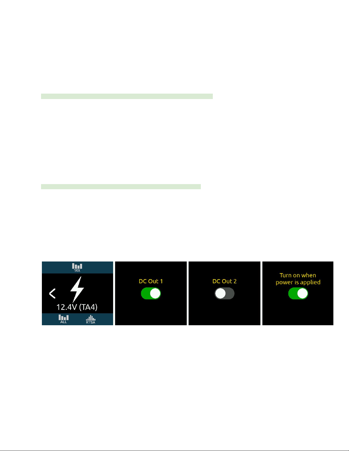
Power Outputs DC Out 1 and DC Out 2
The DC Outs can be used for powering IFB transmitters, camera hops, and other low power peripherals.
Enable or disable each DC Output from the Power menu.
● When powered via its TA4 DC input, the A20-Nexus Go supplies 500 mA maximum between both DC outputs. DC Output
voltage is passed through from the DC input (10-18V).
● When powered by the 8-Series, Nexus supplies 3W maximum for each DC Output. Exceeding this limit may cause
malfunction. Voltage is dependant on 8-Series power source voltage.
A20-Nexus Go User Guide
14

Navigating the A20-Nexus Go User Interface
The A20-Nexus Go is operated from its front panel triangle button, control knob, and four touchscreens.
Triangle Button
● Press to power up. Press and hold to power down.
● When Nexus is powered up, press to cycle between the RX View, Main menu, and RTSA. When on a menu or submenu,
the triangle button exits to the menu above.
Control Knob
● Rotate to scroll through lists and select parameter values. Press to store.
● Rotate to scroll frequency cursor or adjust horizontal/vertical zoom in the RTSA/Scan view.
Touch Screen UI Elements
The A20-Nexus Go uses a number of different UI elements for changing settings i.e. toggle switch, list button, value button, action
button, etc.
Note: When any touchscreen UI element is selected, brightness is reduced and touch is disabled on all other touchscreens.
● Toggle Switch: Tap to toggle between On and Off. Typically used for functions that have on and off states, e.g.
Power>DC Out 1 and DC Out 2.
Off
On
● List Button: Displays a list of items to choose from. A list button is identified by a down arrow inside the button on the
right. The currently selected item is displayed inside the button.
○Tap the list button to display a list of items to choose from.
○Scroll the list of items by rotating the Control or tapping the up/down arrows, then press the Control knob to
select the item and exit the list. Alternatively, tap directly on the list option to select it.
○ To exit the list without making any changes, press the triangle button or tap anywhere on the list’s title bar.
● Value Button: Displays a parameter’s value.
○Tap to select - the button turns orange.
A20-Nexus Go User Guide
15
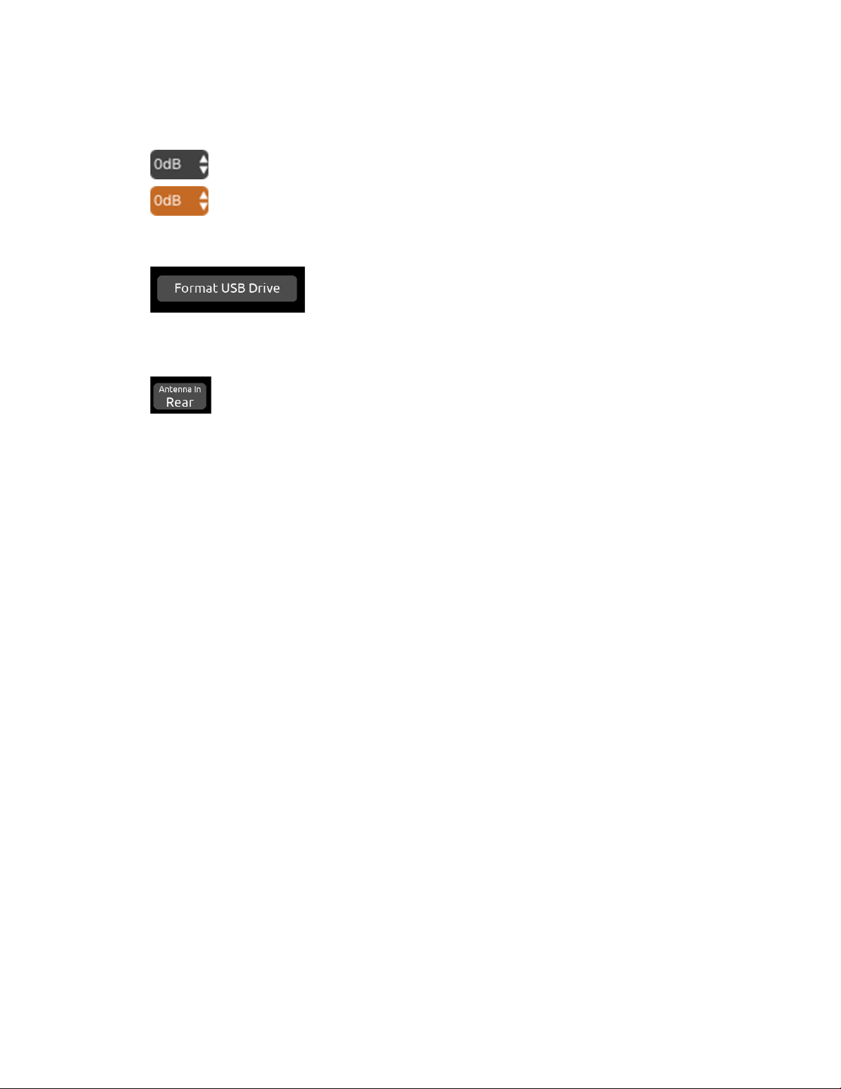
○Rotate the Control knob to adjust the value.
○Press the Control knob or tap the button to exit.
●Action Button: A button that initiates a process, e.g. Format USB Drive. The button contains the name of the process.
● Two-State Button: A button that has two values or options other than On/Off. The top row labels the function and the
bottom row shows the current setting.
A20-Nexus Go User Guide
16
RX Views
RX Views display real-time receiver channel, transmitter signals, and status information across the four touchscreens.
There are several types of RX Views:
● ALL (Displays either 4, 6 or 8 channels, depending on how many channel expansion licenses are installed)
● 4RX View (available when at least one channel expansion license is installed)
● 1RX View
Upon power up, the A20-Nexus Go shows the last displayed RX View.
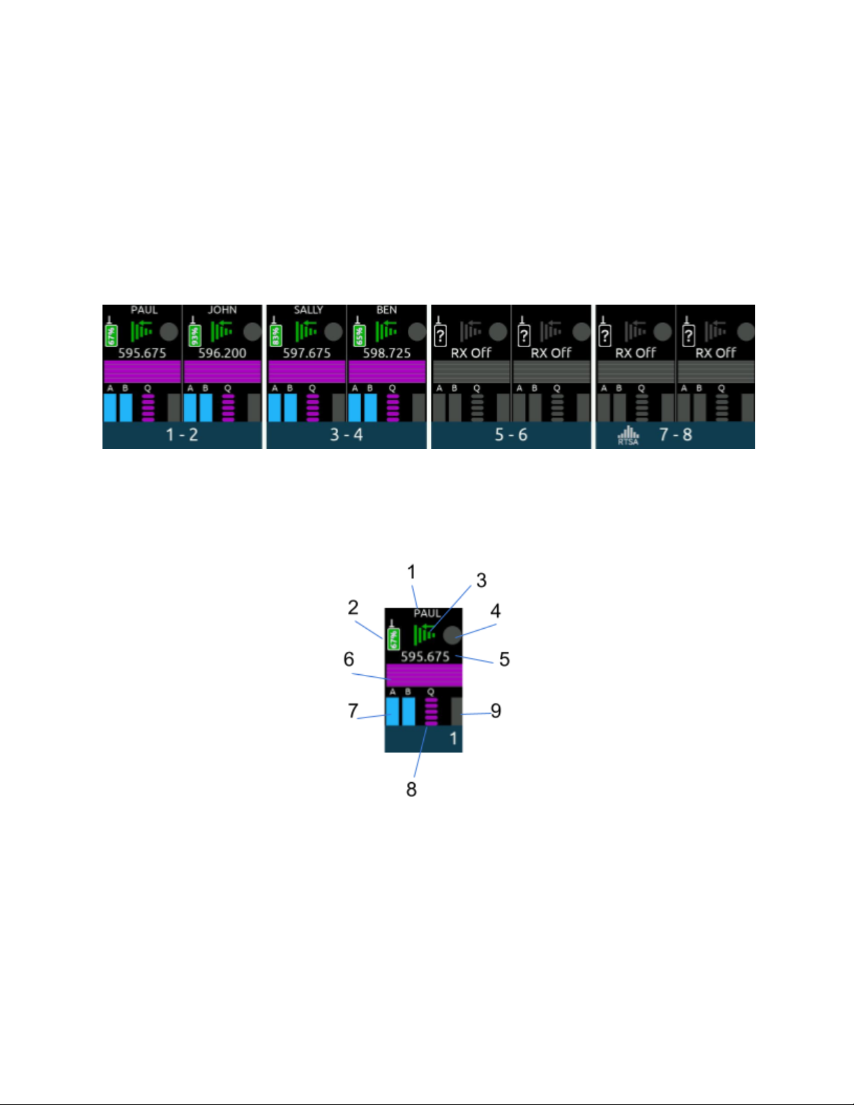
ALL View
(‘All’ View when two 2-ch expansion licenses are installed)
● Displays 8 receiver channel strips, two per screen.
● Tap the right arrow at the bottom of screen four to bank to the next four or eight channels (w/expansion license only).
● Tap two neighboring screens simultaneously to display the 4RX View for those receiver channels. For example, tap
screen 2 and 3 simultaneously to display the 4RX View for receiver channels 3-6.
● Tap any receiver channel strip to display its 1RX View.
1. Channel Name: Displays the name of the transmitters that is currently feeding the channel.
a. The transmitter name can be edited if the channel is NexLinked to an A20 transmitter.
b. The transmitter name cannot be edited if an A10-TX is assigned to it.
2. Transmitter Battery Level Icon: Indicates the remaining transmitter battery charge as a color and in % or V depending
on the type of battery the transmitter is using. If AA or AAA, the battery level is displayed as a voltage. If NP-BX1, then it is
displayed as a %.
a. Gray = Transmitter is Off
b. Green = Good
c. Orange = OK
d. Red = Low
e. Flashing Red = Depleted (transmitter RF and audio are disabled)
3. NexLink RSSI Meter: Indicates the RSSI of the received 2.4 GHz NexLink signal from the transmitter. The RSSI color
signifies the transmitter NexLink status.
A20-Nexus Go User Guide
17

a. Green = Transmitter is on and NexLink active
b. White = Transmitter is off and NexLink active
c. Gray = No connection or out of range
4. Record/Mute Status: Indicates whether the transmitter feeding the receiver channel is recording and/or muted.
a. Red = Recording
b. Blue = Muted
c. Blue fill, red border = Recording and muted
d. Gray = Not recording or muted
5. RF Frequency: Displays the receiver channel’s frequency.
a. If NexLinked to an A20 transmitter and NexLink Tuning Mode is set to Push, it is the same as the transmitter
frequency.
b. Displays ‘RX Off’ when the receiver channel is Off.
c. The frequency flashes red when there is a NexLink issue. Go to the 1RX View > Gear Menu > NexLink Status
screen to determine the cause of the issue.
6. RF History: Displays the receiver channel’s RSSI or Q history. See RF Menu.
7. A and B RSSI Meters: Indicates the strength of the received wireless audio transmission from the transmitter.
8. Q Meter: Indicates the quality of the received wireless audio transmission from the transmitter.
9. Audio Meter: Indicates the received audio level from the transmitter. The audio meter scale is -100 to 0 dBFS for
GainForward sources and -50 to 0 dBFS for non-GainForward sources.
4RX View (or ALL View when no expansion licenses are installed)
● Displays 4 receiver channels, one per screen.
● If at least one channel expansion license is installed, tap the right arrow at the bottom of screen four to go to the next bank
of channels. In the next bank, tap the left arrow at the bottom of screen one to bank to the previous four channels 1-4.
● Tap any receiver channel screen to display its 1RX View.
● Tap the RTSA icon at the bottom of screen 4 to display the RTSA on screen 4.
1. Channel Name and Audio Meter: Displays the transmitter (channel) name inside an audio level meter. Tap the meter to
edit the name (12-character maximum) using the virtual keyboard.
a. The transmitter name can be edited if the channel is NexLinked to an A20 transmitter
b. The transmitter name cannot be edited if the channel is being fed from an A10-TX.
A20-Nexus Go User Guide
18

c. If NexLinked to an A20 transmitter, the name is pushed to the transmitter.
d. The name is rippled to the 8-Series channel that the receiver channel is routed to if docked to an 8-Series and
the 8-Series menu [Channel Setup > Use Wireless Names] is enabled.
2. RF Frequency: Displays the receiver channel’s frequency. Tap to edit the frequency.
a. If NexLinked to an A20 transmitter and NexLink Tuning Mode is set to Push, it is the same as the transmitter
frequency.
b. Displays ‘RX Off’ when the receiver channel is Off.
c. The frequency flashes red when there is a NexLink issue. Go to the 1RX View > Gear Menu > NexLink Status
screen to determine the cause of the issue.
d. Tap the frequency button to select a frequency within the current Tuning Band.
e. To enter a frequency, tap each frequency field then rotate the Control knob to select a value. Tap OK to store or
Cancel to exit without saving. Alternatively, jump through the frequency fields by pressing the Control knob.
f. To save power, turn off a receiver channel by setting the RX On/Off toggle to Off. Alternatively, in the whole
number frequency field (first field), rotate the Control knob fully counterclockwise to display ‘RX Off’.
If NexLinked to an A20 transmitter, the frequency is automatically pushed to the transmitter unless System > More >
NexLink Tuning Mode is set to Manual.
3. HPF: Indicates if the HPF is active either on the transmitter (if an A10-TX) or receiver channel (if an A20 transmitter).
A20-Nexus Go User Guide
19

1RX View
Displays a receiver channel’s received signal, audio level, control functions and status across the four screens.
Use the 1RX View to perform detailed control and monitoring of a receiver channel and its associated transmitter. The 1RX View has
different control layouts depending on the following criteria:
● The model of the transmitter feeding the channel (A20-TX, A20-Mini, or A10-TX).
● Whether the channel is sourced from one or multiple transmitters.
● Whether the channel is sourced from a NexLinked or non-NexLinked (e.g. A10-TX) transmitter.
● Whether the channel’s Mode is set to RF Only, REC Only, or RF+REC
● Whether the A20-Nexus Go is standalone or docked to an 8-Series mixer-recorder
Some 1RX View Layout examples
A20-Nexus
Mode
Description
1RX View Layout
Standalone
REC+RF
Channel sourced from a
single A20 transmitter
(See Example 1 below
for a detailed description)
Standalone
RF Only
Channel sourced from a
single A20 transmitter
Standalone
REC+RF
Channel sourced from
multiple A20 transmitters
(See Example 2 below
for a detailed description)
Docked
RF Only
Channel sourced from a
single A20 transmitter
(expansion license
installed)
Standalone
--
Channel sourced from an
A10-TX or
non-NexLinked
transmitter
Standalone
--
No transmitters are
assigned to the channel.
Tap the TX List button to
assign a transmitter.
A20-Nexus Go User Guide
20
Other manuals for A20-Nexus
1
Table of contents
Other Sound Devices Receiver manuals


