Sound Metrics DIDSON ARIS EXPLORER 3000 User manual


ARIS EXPLORER 3000
GETTING STARTED
Table of Contents
1 INTRODUCTION
2 WHAT’S IN THE ARIS BOX
3 WHAT’S IN THE X2 BOX
4 PAN-TILT ASSEMBLY
5 TILT-ROLL ASSEMBLY
6 ARIScope SOFTWARE
7 CAPTURING QUALITY IMAGES
8 COMPUTER REQUIREMENTS
9 WARRANTY INFORMATION
10 CONTACT US
1INTRODUCTION
THE NEXT GENERATION IN CLARITY
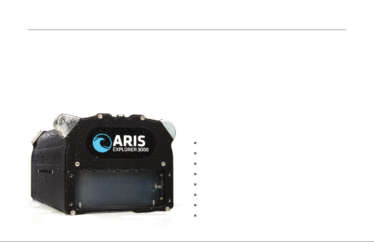
With 128 beams operating at 3MHz, the ARIS Explorer
3000 collects more data than any other imaging sonar
in its class. Users get unmatched image clarity, even in
turbid waters. For longer-range applications, there are
the Explorer 1800 and 1200 models.
The entire ARIS line is built to deliver in the most
challenging situations. A smaller size, newly devel-
oped software and more ecient power usage, makes
the ARIS Explorer family ideal for ROV integration. The
ARIS Explorer 3000 works in zero visibility and operates
in waters from the arctic to the equator.
ARIS EXPLORER 3000
IDENTIFICATION FREQUENCY: 3.0 MHz
DETECTION FREQUENCY: 1.8 MHz
DEPTH RATING: 300m
•Compact and lightweight
•Reliable and Durable
•Export capability to common video file format
•Ethernet communication interface
•Windows recording and playback software
•Real-time system data record, display and control
•Built-in compass and depth gauge
•Pan and tilt controller available as an option
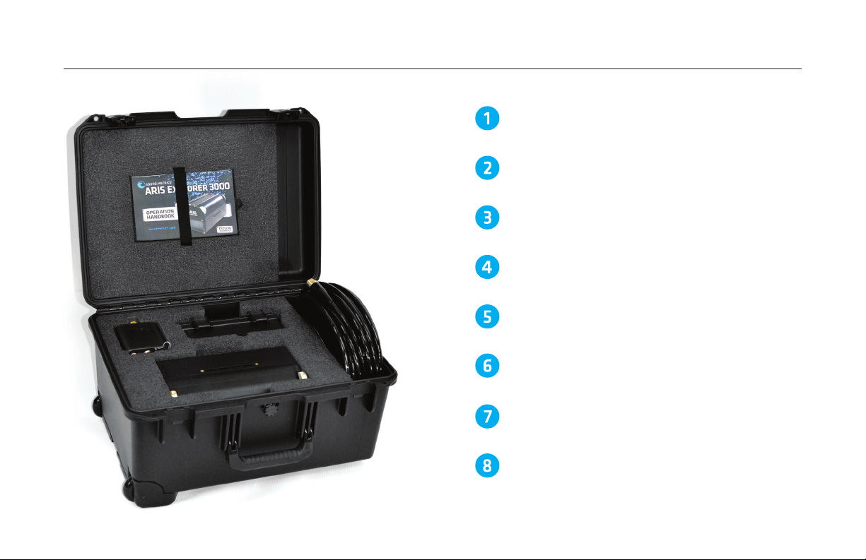
GETTING STARTED HANDBOOK
ARIS SONAR
ARIS CABLE
WATERPROOF BOX
COMMAND MODULE
POWER SUPPLY
ETHERNET CABLE
USB DRIVE & SOFTWARE
2WHAT’S IN THE ARIS BOX?
#012269
#013702
# (Dependent on Length)
#013410
#013470
#014384
#014512
#014385

2WHAT’S IN THE ARIS BOX?
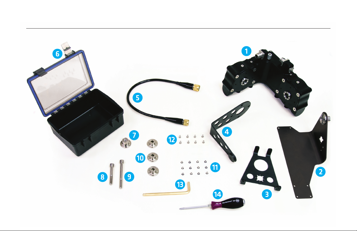
3WHAT’S IN THE X2 BOX?

X2 ROTATOR
PAN-TILT BRACKET
ROLL BRACKET
TILT BRACKET
X2 CABLE
WATERPROOF BOX
MOUNTING NUT (2)
One pre-installed on Pan-Tilt Bracket
3WHAT’S IN THE X2 BOX?
10mm x 70mm BOLT
10mm x 100mm BOLT
MOUNTING WASHER (3)
FLAT-HEAD 5mm x 8mm SCREWS (12)
HEX-HEAD 5mm x 10mm SCREWS (8)
8mm HEX DRIVER
PHILIPS SCREW DRIVER
#014471
#014337
#014266
#012337
#014361
#013410
#012473
#012506
#012505
#012475
#012358
#014386
#013549
#013156

4PAN-TILT ASSEMBLY
EXPLODED VIEW
There are other possible configurations than those shown.
STEP 1
Attach Mounting Nut and Mounting Washer to shaft with Flat-Head
5mm x 8mm Screws. Using 10mm x 100mm Bolt attach X2 Rotator to
the customer supplied Pole.
STEP 2
Attach Mounting Washer to shaft with 5mm x 8mm Screws. Attach
Pan-Tilt Bracket to shaft by slipping the Mounting Nut into the shaft
and tightening with the 10mm x 70mm Bolt. Make sure the arrows
on the Bracket are pointing away from the Connectors on the X2.
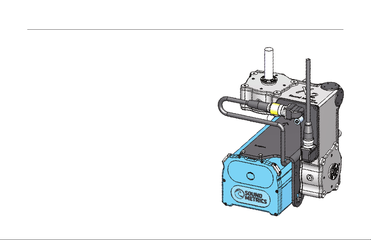
STEP 3
Attach Cable to the ARIS and to the Connector on the X2.
STEP 4
Attach ARIS to Pan-Tilt Bracket using Hex-Head 5mm x 10mm Screws.
STEP 5
Attach Cable from Topside Box to the X2 Rotator.
NOTE
“Home” position is re-set at every power up. To ensure maximum move-
ment limits are acceptable, manually move the sonar before power up or
with the control buttons after power up to a horizontal position (or your
chosen “Home”), then click the “Set Zero” in the X2 Settings menu in
the ARIScope Software.
4PAN-TILT ASSEMBLY
COMPRESSED VIEW

5TILT-ROLL ASSEMBLY
STEP 1
Attach Mounting Nut to Roll Bracket using
Flat-Head 5mm x 8mm Screws.
STEP 2
Attach Roll Bracket to ARIS using the Hex-Head
5mm x 10mm Screws.
STEP 3
Attach Tilt Bracket to X2 Rotator using
Flat-Head 5mm x 8mm Screws.
STEP 4
Attach the Mounting Washer to the X2 Rotator using
the Flat-Head 5mm x 8mm Screws. Attach the ARIS
and Roll Bracket to the X2 using the 10mm x 70mm Bolt.
STEP 5
Attach the X2 Cable to the ARIS and X2 Rotator.
STEP 6
Using the 10mm x 100mm Bolt, Mounting Screw
and Mounting Nut attach the X2 shaft to the
customer supplied mount.
STEP 7
Using customer supplied 10mm Bolt attach
Tilt Bracket to customer supplied mount.
STEP 8
Attach Cable from the Topside box to the X2 Rotator.
NOTE
“Home” position is re-set at every power up. To ensure
maximum movement limits are acceptable, manually
move the sonar before power up or with the control
buttons after power up to a horizontal position (or your
chosen “Home”), then click the “Set Zero” in the X2
Settings menu in the ARIScope Software.

5TILT-ROLL ASSEMBLY
EXPLODED VIEW
COMPRESSED VIEW
There are other possible configurations
than those shown.

6ARIScope SOFTWARE

TOP BAR
•SMC Logo
•Sonar Icon
•Icon Scroll Buttons
•Open File Icon
•Files Icon
•Settings Icon
•Help Icon
CONTROL PANEL
•Panel Expand/Collapse Button
•Sonar Control Button
•X2 Settings Button
•Image Control Button
•Filters Button
IMAGE DISPLAY
•Range Control
•Zoom Control
•Orientation Control
•Acoustic Image
•X2 Control
STATUS PANEL
•Panel Expand/Collapse Button
•Master
•Sonar Status
•Platform Status
6ARIScope SOFTWARE

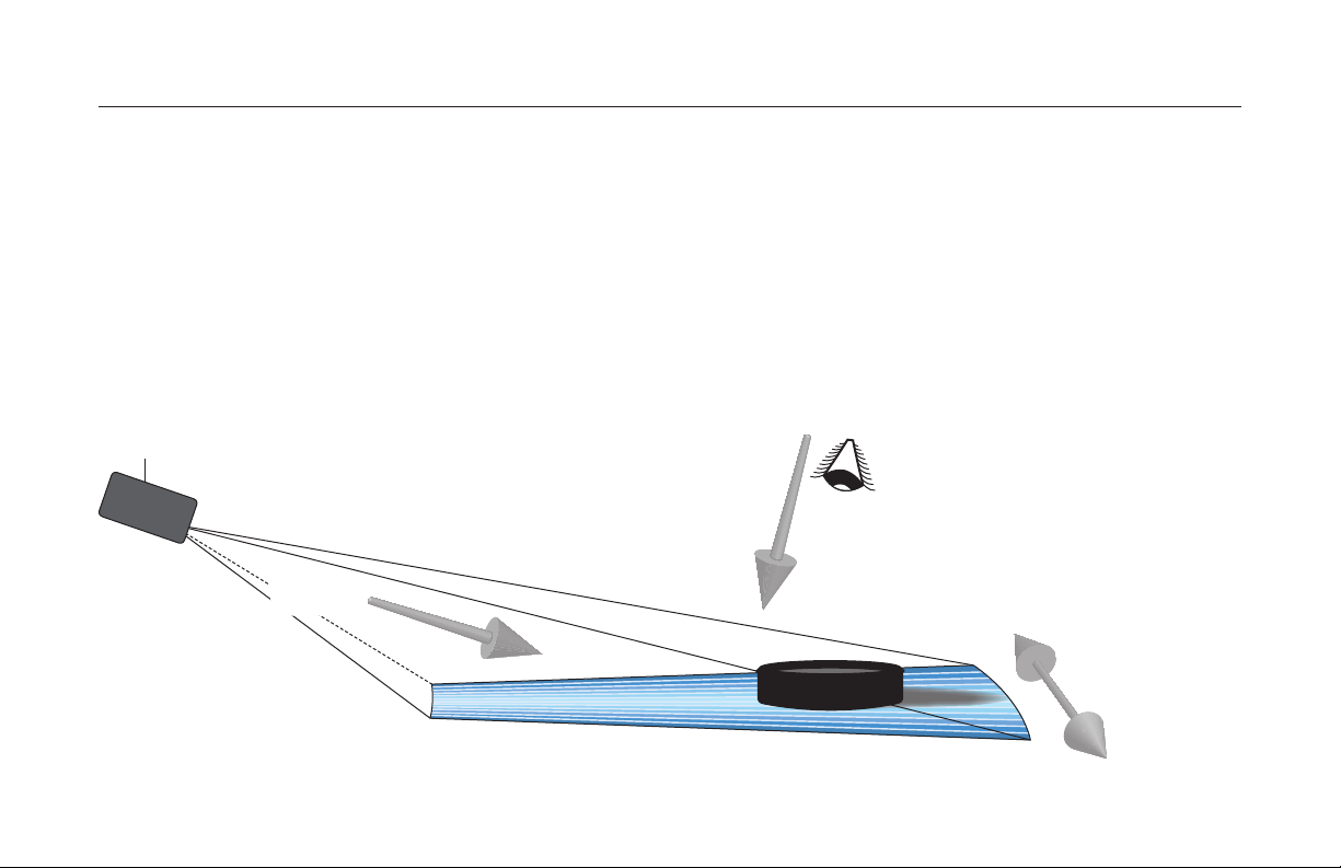
The following illustrations demonstrate how to image a flat object lying on a flat bottom.
7CAPTURING QUALITY IMAGES
ACOUSTIC VOLUME
The ARIS multi-beam sonar projects a wedge shaped
volume of acoustic energy much like a flashlight projects
a cone shaped volume of light.
ARIS
PERSPECTIVE VIEW
RANGE, CROSS-RANGE & IMAGE PERSPECTIVE
Three terms concerning distance and direction relative to the acoustic wedge are Range, Cross-Range, and Image
Perspective. Each of these are at 90 degrees to the other two, much like the 3 edges that come together at the
corner of a box. Range refers to distance away from the ARIS along the length of the wedge. Cross-Range speaks to
distance directly across the width of the wedge. Image Perspective speaks to direction coming from above viewing
directly down on the wedge.
7CAPTURING QUALITY IMAGES
ARIS
CROSS-RANGE
RANGE

7CAPTURING QUALITY IMAGES
The width of the acoustic wedge is a fan of narrow
slices. Each slice from a beam of ARIS produces a
thin strip of the image aligned with range which is
placed appropriately with neighbors in cross range
to produce the entire image.
RANGE SETTING
Orient the ARIS such that the acoustic wedge
impacts the object so that the surface is shown
in range and cross-range. Keep in mind that
the aim of ARIS is 90 degrees from the image
perspective. Along with aiming the unit, drag
the sliders in ARIScope to set the start and end
ranges of the image window.
ARIS
END RANGE
START RANGE
ARIScope
RANGE CONTROLS

7CAPTURING QUALITY IMAGES
The ARIS image is from the perspective view showing Range and Cross-Range information.
RANGE
ARIS
CROSS-RANGE

8COMPUTER REQUIREMENTS
MINIMUM PC REQUIREMENTS¹
•Windows 7 32-bit SP1
•DirectX 10 compatible graphics
•1.8 GHz Dual-Core CPU
•2 GB RAM
•256 MB Video RAM
•20 GB Free disk space (for recording)
RECOMMENDED PC CONFIGURATION²
•Windows 7 64-bit Professional SP1
•DirectX 11 compatible graphics
•2.2 GHz quad-core CPU
•4 GB RAM
•512 MB Video RAM
•200 GB free disk space (for recording)
RECOMMENDED PC UPGRADES³
•SSD C:\ Drive (Solid State Disk)
•8 GB RAM
•1 GB Video RAM
¹ For good performance using ARIScope software, and
limited functionality for future image processing
² For great performance using ARIScope software, and
good performance on future image processing
³For great performance using all present and planned
ARIS software

9WARRANTY INFORMATION
WHAT TO DO IN CASE OF A PROBLEM WITH THE
ARIS EXPLORER
Sound Metrics Corp. (SMC) warrants the ARIS Explorer
for one year according to the terms of the official
warranty document. If the sonar appears to be defective
please contact SMC by email or phone to discuss
your options. In many cases we can help resolve
issues without having to return the unit, but if not,
SMC pledges to repair your sonar as quickly as possible.
For sonar returns, you need to contact SMC for a “Case
Number” and provide details of the problem(s) - this
allows us to prepare so your sonar can be repaired
and returned to you quickly. We ask that you ship the
sonar in its original protective storage case. If still
under warranty the unit will be repaired and returned
to you at no cost; otherwise you will be charged for
parts, labor and return shipping. We will provide you
with an estimate of any repair and wait for approval
before proceeding with the work.
In most cases, it is not advisable to open or attempt
to repair the sonar in the field. However, this may be
the only option if time is critical. SMC is best qualified
to make that determination and our personnel can
provide step-by-step instructions if that is determined
to be the best course of action. Your warranty may
be void if you attempt such servicing without first
contacting SMC.
Sound Metrics Corp., Inc.
11010 Northup Way
Bellevue, WA 98004
PHONE: 425-822-3001
WEBSITE: www.SoundMetrics.com

ARIS EXPLORER LIMITED WARRANTY
Sound Metrics Corp. (SMC) warrants that the ARIS Explorer (“Product”)
will be free from defects in materials and workmanship under normal
usage for one year from the date the Product is shipped to the first
purchaser of the Product (“Warranty Period”), unless SMC has agreed
in writing to alter any of the foregoing terms.
Any implied warranties, including without limitation the implied
warranties of merchantability and fitness for a particular purpose,
shall be limited to the duration of this limited warranty, otherwise the
repair, replacement, or refund as provided under this express limited
warranty is the exclusive remedy of the consumer, and is provided
in lieu of all other warranties, express or implied. In no event shall
SMC be liable, whether in contract or tort (including negligence) for
damages in excess of the purchase price of the product, or for any
indirect, incidental, special or consequential damages of any kind,
or loss of revenue or profits, loss of business, loss of information or
data, software or applications or other financial loss arising out of or in
connection with the ability or inability to use the product to the full
extent these damages may be disclaimed by law.
Some states and jurisdictions do not allow the limitation or exclusion
of incidental or consequential damages, or limitation on the length
of an implied warranty, so the above limitations or exclusions may
not apply to you. This warranty gives you specific legal rights, and
you may also have other rights that vary from state to state or from
one jurisdiction to another. This warranty extends only to the first
purchaser of the Product, and is not transferable.
This limited warranty is your exclusive remedy, and applies to
new Product purchased in the United States or Canada, which are
accompanied by or sold with this written warranty.
If the Product proves defective during the warranty time period,
please contact SMC by email or phone to discuss options for repair or
replacement at the sole option of SMC. SMC will, in a timely manner,
provide you an option for repair or replacement but that, in any event,
SMC will repair or replace your Product in a commercially reasonable
time. For warranty work, you must first contact SMC for a “Case
Number” and provide details of the problem(s) - this allows preliminary
preparation so your Product can be repaired or replaced as necessary.
We ask that you ship the Product to SMC or SMC’s designated repair
depot in its original protective storage case. The Product will be
repaired or replaced and returned to you at no cost. SMC reserves
the right to use functionally equivalent conditioned/refurbished/
pre-owned or new parts in the case of repair or replacement. In
most cases, it is not advisable to open or modify the Product in any
manner. However, this may be the best initial action if time is critical.
SMC is best qualified to make that determination and their personnel
can provide step-by-step instructions if that course of action is
determined best at SMC’s sole discretion. Any attempt to alter the
Product in any manner or the misuse or abuse of the Product may void
your warranty.
LAST REVISION 07-03-2013
9WARRANTY INFORMATION
Table of contents


