Sound Sculpture SWITCHBLADE ET User manual
SWITCHBLADE ET
OWNER’S MANUAL
Document OMSBET_10X211116B

1
Limited Warranty
Sound Sculpture Musical Instrument Products (Sound Sculpture) warrants this Switchblade ET to the original purchaser to be free of defects in
material and workmanship under normal use for a period of 2 years from the date of purchase from an authorized Sound Sculpture dealer or
directly from Sound Sculpture.
Sound Sculpture's liability under this warranty is limited to repairing or replacing defective materials that show evidence of defect, and only if
the product is returned for repair directly to Sound Sculpture or to the authorized Sound Sculpture dealer from which the unit was purchased.
Sound Sculpture reserves the right to make changes in design or make additions or improvements on the product without incurring any
obligation to install the same on products previously manufactured.
Sound Sculpture shall not be liable for any consequential damage or loss of profits as a result of the use of this product even if Sound Sculpture
is advised of the possibility of such damages or loss. In no event will Sound Sculpture's liability exceed the price paid for the product.
No other warranties are expressed or implied and Sound Sculpture neither assumes nor authorizes any person to assume for it any obligation or
liability in connection with the sale of this product. In no event shall Sound Sculpture or its dealers be liable for special or consequential
damages due to the use of this product. Some states do not allow the exclusion or limitation of incidental or consequential damages, so the
above exclusions or limitations may not apply to you.
In Case of Difficulty
In the unlikely event that you experience problems with the Switchblade ET, please refer to the section in this manual pertaining to the
operation you are having difficulty with. Very often the difficulty is simply a result of improper setup or programming and can be resolved by
studying this manual.
If, after reading this manual, you are unable to resolve the problem email Sound Sculpture at [email protected] or call at the number
below during normal business hours. If we are unable to resolve your problem over the phone and determine that the unit needs repair, you
will be given a return authorization number and further procedures for returning the unit. UNAUTHORIZED REPAIR OF THE
SWITCHBLADE ET VOIDS THE WARRANTY. NO UNITS WILL BE ACCEPTED FOR REPAIR WITHOUT FIRST CONTACTING
THE FACTORY FOR A RETURN AUTHORIZATION NUMBER.
Precautions and safety notes
To reduce the risk of fire or electric shock, do not expose this unit to rain or operate this unit in a wet environment.
Do not attempt repairs on this unit. Refer all servicing to the factory.
If the unit becomes physically damaged due to dropping or for other reasons, it should be returned to the factory for repair to avoid the risk of
further damage to the unit. Do not power up the unit if it has been damaged.
To avoid damage due to overheating this unit should not be exposed to, or operated in, direct sunlight for extended periods of time.
To avoid damage due to lightning, this unit should be unplugged during an electrical storm.
Copyright by Sound Sculpture LLC
Bend, OR –USA
This publication may not be reproduced by any means in whole or in part except for personal use without written consent from
Sound Sculpture Musical Instrument Products.

2
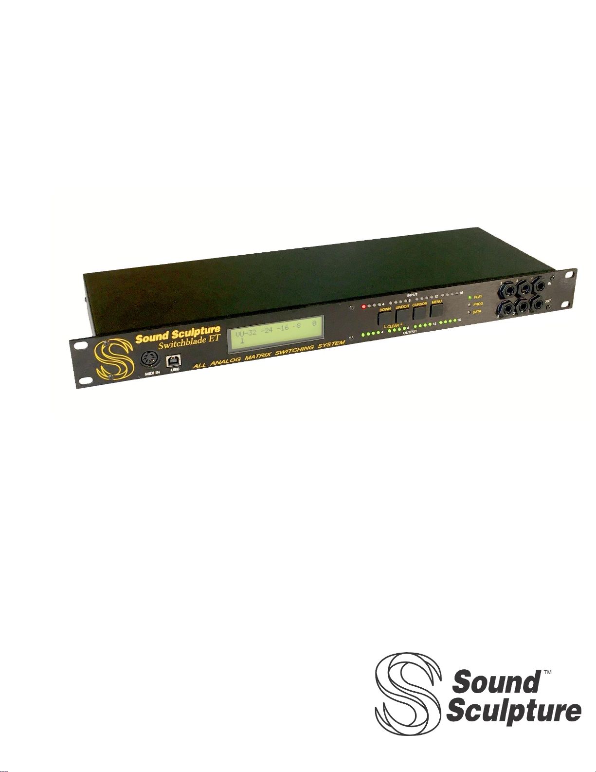
Congratulations on your purchase of the Switchblade ET. You now own a member of the most advanced effect switching
systems available. The Switchblade ET has a wealth of features that will take time to learn. To get you up and running as
quickly as possible, we’ll start things off by giving you 3 examples to try out at the beginning of this document which will get
you oriented as quickly as possible. After that, the best way to learn how to use the unit is simply to read about how each menu
works.
FEATURES ________________________________________________________________________ 4
USES ______________________________________________________________________________ 4
LAYOUT ___________________________________________________________________________ 5
QUICK START______________________________________________________________________ 6
GEAR SETUP _____________________________________________________________________________________ 6
SWITCHBLADE SETUP ____________________________________________________________________________ 6
PRESET PROGRAMMING __________________________________________________________________________ 7
GENERAL INFORMATION ABOUT USING THE SWITCHBLADE _________________________ 8
CONTROLLING THE SWITCHBLADE ________________________________________________________________ 8
SMART INSERT ___________________________________________________________________________________ 8
CONTROL RELAYS (FOOTSWITCH SIMULATORS)____________________________________________________ 8
PRESET NORMALIZING: ___________________________________________________________________________ 9
CONTINUOUS CONTROL USING MIDI OR EXPRESSION PEDALS _______________________________________ 9
USING THE SWITCHBLADE TO CONTROL OTHER MIDI DEVICES ______________________________________ 9
VU METER LED AND BARGRAPH DISPLAY_________________________________________________________ 10
AUTOSWEEP ____________________________________________________________________________________ 10
THE MENUS ______________________________________________________________________ 10
THE PLAY, PROGRAM SELECT, AND VU MENUS _____________________________________ 11
THE PLAY MENU ________________________________________________________________________________ 11
THE VU METER MENU ___________________________________________________________________________ 12
THE PROGRAMMING TREE SELECTION MENU______________________________________________________ 12
THE PRESET MENU GROUP________________________________________________________ 13
PRESET NAME MENU:____________________________________________________________________________ 13
THE PATCHING MENU: ___________________________________________________________________________ 13
REVIEW MENU:__________________________________________________________________________________ 14
THE MIDI OUT PROGRAM CHANGE MENU _________________________________________________________ 14
THE MIDI OUT CONTROL CHANGE MENU__________________________________________________________ 15
RELAY STATES__________________________________________________________________________________ 16
THE AUTOSWEEP MENU _________________________________________________________________________ 16
THE IO/MIDI MENU GROUP________________________________________________________ 17
THE INPUT-OUTPUT NAMING MENU: ______________________________________________________________ 17
THE INPUT-OUTPUT LEVELS SETTING MENU ______________________________________________________ 18
SMART INSERT MENU: ___________________________________________________________________________ 18
MIDI CHANNEL ASSIGNMENT MENU: _____________________________________________________________ 19
MIDI OUT ASSIGNMENT MENU: ___________________________________________________________________ 20
RETRANSMIT MENU:_____________________________________________________________________________ 20
THE "MORE" MENU GROUP _______________________________________________________ 20
FOOTSWITCH ASSIGN MENU:_____________________________________________________________________ 21
PRESET MANAGER MENU:________________________________________________________________________ 22
PRESET SWITCH TIME MENU _____________________________________________________________________ 23
RELAY TYPE MENU: _____________________________________________________________________________ 23
DISPLAY MENU: _________________________________________________________________________________ 24
THE COPY MENU:________________________________________________________________________________ 24
EXPRESSION PEDAL CALIBRATION MENU: ________________________________________________________ 24
FRONT PANEL OUT GROUND MENU: ______________________________________________________________ 25
FOOTSWITCH SCHEMATIC ________________________________________________________ 26

3
SYSTEM EXCLUSIVE OPERATION ___________________________________________________26
FEATURE CHANGES FROM PREVIOUS SWITCHBLADE MODELS ______________________27
FRONT PANEL LED ARRAY _______________________________________________________________27
IN PLAY MODE __________________________________________________________________________________ 27
VU METER MENU (FROM PLAY MODE)_____________________________________________________________ 27
WHILE IN THE PATCHING MENU __________________________________________________________________ 27
REVIEW MENU __________________________________________________________________________________ 27
INPUT AND OUTPUT LINE/INSTRUMENT TRIM SETTINGS __________________________________28
INPUT TRIM _____________________________________________________________________________________ 28
OUTPUT TRIM ___________________________________________________________________________________ 28
FULLY INSTRUMENT LEVEL SETUP _______________________________________________________________ 28
HOW LINE AND INSTRUMENT DEVICES WORK TOGETHER IN A PRESET ______________________________ 28
SPECIAL CONSIDERATIONS_______________________________________________________________________ 28
ADDITIONAL NEW FEATURES_____________________________________________________________29
FRONT PANEL AUDIO JACKS______________________________________________________________________ 29
EXPRESSION PEDAL INPUTS ______________________________________________________________________ 29
8 SIMULTANEOUS CONTROLLERS ALLOWED ______________________________________________________ 29
FOOTSWITCH INPUT _____________________________________________________________________________ 29
FOOTSWITCH SIMULATOR JACKS _________________________________________________________________ 29
ADDITIONAL CC AND PROGRAM MESSAGES _______________________________________________________ 29
3 LOW FREQUENCY OSCILLATORS (LFO) __________________________________________________________ 29
USB PORT _______________________________________________________________________________________ 29
FRONT PANEL MIDI JACK_________________________________________________________________________ 29
ABILITY TO MONITOR BOTH INPUT AND OUTPUT VU _______________________________________________ 29
EXPANDED SYSEX COMMAND SET ________________________________________________________________ 30
INTERNAL ENHANCEMENTS______________________________________________________________________ 30
ADDITIONAL HINTS ______________________________________________________________________30
QUESTIONS AND ANSWERS _______________________________________________________________30
MIDI CONTROL CHANGE AND PROGRAM CHANGE MESSAGES________________________31

4
FEATURES
The Switchblade ET is packed with features not available with any other switching system on the market.
•All analog audio path with superb audio quality and silent preset changes
•Top quality buffers on each input and each output to overcome cable and effect deficiencies.
•Ability to route effects in series (in any order), in parallel, or in complex series/parallel combinations and save in a preset.
Changing presets changes all the wiring in a virtual instance.
•Presets can include selecting different instruments or, if using with several amps, turning on different amp combinations.
•Also, in a preset you can include setting levels at every input to output connection (not just inputs or outputs) giving you the
power to mix effects together for the most beautiful tones.
•Assign up to 8 controllers (such as expression pedals) to any connections in a preset for volume swelling or crossfading
effects.
•Controllers can include 2 direct expression pedal inputs, MIDI Control Change messages from a MIDI foot controller for
example, or 3 built in Autosweeps (Low Frequency Oscillators or LFOs)
•Control the switching of the channel and reverb on your amp either with a preset or directly using MIDI using the 6 internal
contact closure relays
•Control preset changes and other functions using a MIDI controller or a simple mechanical footswitch
•A footswitch can be set to scroll through presets, select presets randomly using a Preset Manager function, boost/cut gains,
tap tempo the Autosweeps, toggle the amp channel/reverb relay functions, transmit up to 4 on/off Control Change messages
to external effects, or normalize preset levels.
•Use the Switchblade as a MIDI controller to transmit Program Change, on/off Control Change, and continuous Control
Change messages to additional MIDI devices.
•Use Control Change on/off messages (instant access switches) to intelligently remove and re-inset effects, instruments, and
amps within a preset using the Smart Insert feature.
•Monitor each input and output level using the VU meter function.
•Easily copy presets to other preset locations
•Remote operation through USB or a standard MIDI computer interface
USES
The Switchblade ET was designed around a versatile open architecture that allows an imaginative array of different ways to
create simple or complex systems expanding your rig in ways you never dreamed. As you familiarize yourself with the
Switchblade you may find yourself asking "Can I do this?" and chances are, now you can. Below are some examples to get you
started. This is by no means an exhaustive list.
•Create presets that wire effects together in different ways then switch between presets to do A/B comparisons to find out
whether an effect sounds best before or after another effect or in parallel instead of series.
•Connect any number of amps to your system and switch between them or combine them, setting the levels going to each
amp independently. Changing presets changes your amp selections and levels.
•Connect any number of instruments and select between them by changing presets or using instant access switches, or select
several instruments simultaneously to allow several musicians to share effects
•Add a microphone preamp to the system to share your effects among your vocals and instruments.
•Use the Smart insert feature to select instruments, amps, and effects for unprecedented control when using looping devices
to create multiple layers of effects and vocals.
•Use an expression pedal to increase the drive on the input of an overdrive (from any start gain to any end gain) while
simultaneously lowering the output level (between any other start and end gain) to increase overdrive while decreasing the
output level at the same time. Do the same thing with a delay to increase your delay presence as the volume decreases.
•Connect a dry bypass in parallel with any effect or group of effects to change the wet/dry ratio under preset or expression
pedal control.
•Connect the output of a delay to several effects in series and connect the output of that series back into the delay input to
create effect buildup with each echo.
•Use the 3 available Autosweeps (LFOs) to cross fade between separate networks of effects for a super tremolo type sound
with a changing tone during each sweep cycle. Each Autosweep can be set to its own time offering up to 3 tremolos which
can be placed anywhere in the effect network.
•Combine magnetic/piezo/and MIDI synth signals from your guitar on a preset or continuous basis.
•Use the Autosweep One Shot Switch to change presets automatically at the end of a single sweep to endlessly splice
together presets for massive dynamic sound changes.
5
LAYOUT
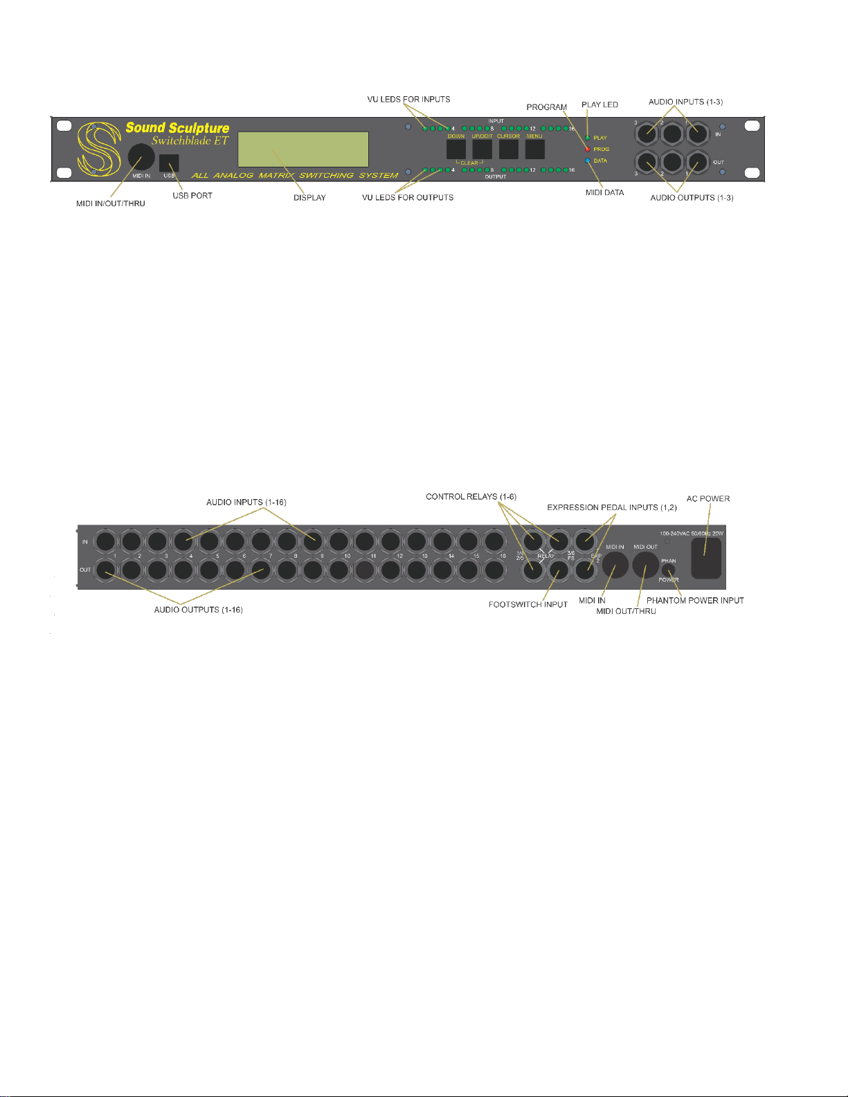
MIDI IN/OUT/THRU: This is an alternate MIDI IN jack for convenience and works the same as the MIDI IN on the back panel. Using a
special connector, you can also tap off of the MIDI OUT/THRU function for special purposes. Phantom power is supplied on this jack as well.
USB PORT: Standard USB type A connector to connect to a computer or iPad.
DISPLAY: Displays various menus for different modes.
VU LEDS (FOR INPUTS AND OUTPUTS): Top row shows the signal levels of inputs 1-16. Bottom row shows outputs 1-16. The LEDs
glow green in proportion to the strength of the signals. Overload conditions are indicated with red.
PANEL SWITCHES: The MENU switch moves the display to the next menu. CURSOR moves the cursor around a menu. The UP/DOWN
switches increment/decrement presets and parameters in each menu.
STATUS LEDS: The green PLAY LED lights whenever the unit is in the normal operation menu during playing. The red PROG LED lights
if the unit is in any of the programming menus. The blue DATA LED blinks whenever a recognized MIDI command is received (a Program
message or Control Change message over the correct MIDI channel).
AUDIO INPUTS 1-3: These inputs can be used instead of inputs 1-3 on the back panel for easy connection to instruments.
AUDIO INPUTS 1-16: These inputs connect to your instruments, effects, or other audio sources.
AUDIO OUTPUTS 1-16: These outputs connect to your amplifiers, effects, or other audio destinations.
CONTROL RELAYS 1-6: These 3 TRS outputs are used to connect to the footswitch inputs on your amp to control the channel or reverb on
your amp.
EXPRESSION INPUTS 1 & 2: These 2 TRS (tip-ring-sleeve) inputs are used to connect up to 2 expression pedals to control the gains
throughout your preset network in real time for volume swelling and panning.
FOOTSWITCH INPUT: This TRS input accepts a common triple momentary footswitch to control the Switchblade if not using MIDI for
control. May be used in addition to MIDI.
MIDI IN CONNECTOR: Standard MIDI IN connector to connect to the MIDI out on a MIDI foot controller or other MIDI device. This is a
7-pin connector to allow for phantom powering.
MIDI OUT/THRU CONNECTOR: Passes MIDI data from the MIDI in connector to the next MIDI device in your effect chain. If the
Switchblade is transmitting its own data, it will momentarily change to a MIDI OUT but always merges with any incoming data, so no MIDI is
lost.
PHANTOM POWER JACK: This jack connects directly to pins 6 and 7 of both front and rear MIDI IN connectors and can be
connected to any user supplied power source to supply phantom power to appropriate MIDI foot controllers through the MIDI IN
jack. The supply that comes with the MIDI controller is typically used here.
POWER INPUT: 100-240VAC 20W standard IEC type power connector.

6
QUICK START
To get you up and running as quickly as possible follow the steps in this section which describe connecting your gear (GEAR
SETUP), doing some initial Switchblade setup (SWITCHBLADE SETUP), and finally programming a preset to hear sound
(PRESET PROGRAMMING) It's assumed you are using a MIDI foot controller to select presets on the Switchblade. Only
basic instructions are given here to get you started. For more advanced control details see the individual menu descriptions.
GEAR SETUP
1. Connect your instruments and effect outputs into any of the INPUT jacks and connect your amps and effect inputs to any of
the OUTUT jacks. It makes no difference where you connect your effects, instruments, and amps as this is all sorted out
when you give names to the inputs and outputs. For example, if you have 2 guitars and 3 amps, you can connect your
guitars into inputs 2 and 5, your amps into 3, 4, and 8 and a mono effect into input 1 and output 7 with no effect on sound or
operation. For esthetic reasons, or depending on where your cables are laid out in your rack, you may find it logical or
convenient to connect your instruments and amps into like numbered inputs and outputs (such as input 1, 2 and output 1, 2,
3) and your mono effects into like numbered inputs and outputs (like input 4 and output 4), but again, you don't have to. For
stereo effects, you will need to use 2 inputs and 2 outputs, (or 1 output and 2 inputs for mono in/stereo out effects) and
again, any inputs or outputs will do.
2. Set the input levels and output levels on your effects that have such controls to the mid points or set them so the input to
output signal ratio is approximately unity gain (what goes in is the same level as what comes out). The reason for this is so
you won't get excessive gain buildup when putting effects in series.
1. If you are using a MIDI foot controller to select presets on the Switchblade, then plug the controller’s MIDI OUT into the
Switchblade’s MIDI IN. Be sure to transmit the messages on the same MIDI channel as the Switchblade. The MIDI
channel of the Switchblade is set to channel 1 when shipped but can be changed using the MIDI Channel menu in the
IO/MIDI group.
SWITCHBLADE SETUP
NOTE: You must create names for all inputs and outputs you have connected to gear using the IN/OUT NAMING menu as
programming a preset depends on having the inputs and outputs named.
1. When the Switchblade powers up, the green "PLAY" indicator should be on. If it is not, press the MENU switch until it is.
This is play mode, used when you are (..um) playing.
2. Press the MENU switch once to enter the programming group selection menu (PROGRAMMING GROUP).
3. Press the CURSOR switch so the cursor (underscore) is under "IO/MIDI".
4. Press the MENU switch again to move to the input/output configuration menu (INPUT OUTUT CONFIG)
5. Each input and output that is used should be set to either LINE or INST (instrument) level to match the connected device.
Guitars, amps, and guitar stomp boxes and rack effects with instrument inputs and outputs should be set to INST. Rack
effects that have line level inputs and outputs should have those outputs and inputs on the Switchblade set to LINE.
6. Press the MENU switch again to move to the Input/Output Naming menu (IN/OUT NAMES). All connections in a preset
are made using names to keep your life easy.
7. The cursor will be under IN 1 when entering this menu. If you have something connected to this input, then move the cursor
to the lower left corner and use the UP and DOWN buttons to scroll through letters, numbers, and symbols to give a name to
this input. For example, GUITAR if you have a guitar connected to input 1 or OD if you have an output from your
overdrive pedal connected to this input. Names can be up to 8 characters long.
8. Move the cursor back under IN 1 and press UP to get to the next input number in which you have something connected.
Give names to all inputs where you have a device or instrument connected and leave any unconnected inputs blanked out.
9. When all used inputs are named move the cursor under IN x again and press UP until you reach OUT 1. Go through all the
output numbers and name all outputs that are connected to devices. Leave any unused outputs blank. For example, AMP 1,
AMP 2, OD, and so on.
10. NOTE: When naming a connected mono effect, it's easiest if you just give the input and output the same name, such as
DELAY for the input name and DELAY for the output name. Avoid the temptation of using names such as DELYIN and
DELAYOUT thinking this will make your life easier, it will not.
11. NOTE: If using stereo effect devices, give each of the 2 inputs and 2 outputs a different name, such as FX LEFT and FX
RIGHT (for both the inputs and outputs). If the effect has a mono input and stereo output then using 3 names is appropriate
such as FXL, FXR, and FX for the 2 inputs to the Switchblade and the 1 output from the Switchblade.
12. NOTE: When any OUT number is showing, the lower right corner will display FINLOUT> NO. This can be ignored for
now but is related to the use of the preset normalizing or boost feature where you can adjust the overall levels of each preset
with respect to each other or to boost/cut levels during a performance.

7
PRESET PROGRAMMING
For this section, 2 example presets will be programmed. Preset 1 will wire two effects in series and preset 2 will wire 2 effects in
parallel. One guitar and one amp will be used.
PRESET 1
1. If not in the play mode (green LED lit), repeatedly press the MENU button until you are. Once in play mode select preset 1
using the UP/DOIT or DOWN switch while the cursor is under the preset number.
2. Press the MENU switch to enter the Programming Group Selection Menu, leave the cursor where it is to enter the Preset
group, and press the MENU switch again to move directly to the Preset Naming menu (PRESET NAME).
3. Using the UP, DOWN, and CURSOR buttons, create a name for your preset.
4. Press MENU to get to the Preset Patching Menu. This menu is where all connections in a preset are made and other than the
Preset Naming Menu may be the only other preset programming menu you may need to use.
5. If not already there move the cursor to the upper left corner. This is the "source" area and using the UP/DOWN buttons you
can scroll through all the available named inputs. This is the reason you named the inputs and outputs in the setup menu
group (no need to memorize input/output numbers). Scroll through the names until you reach the name of your instrument
(such as GUITAR). This will be the start of your audio signal path.
6. Move the cursor to the upper right corner. This is the "destination" area, and this area displays all the outputs that are
named. For this preset of 2 effects in series, scroll until you reach the name of an effect you have attached. For this
example, we'll use FX2.
7. Now that we have the source (guitar) and the first place the guitar goes to (FX2), move the cursor down to the lower left
corner. This is the "gain" area and will display OFF which means there is no connection between these 2 devices. Press and
hold the UP button until the gain says "0dB" which is the gain of a straight wire. (no gain, no loss).
8. Now that you have 1 connection made, we need to make another connection from FX2 to FX1 to put these two effects in
series. Repeat steps 5-7 but put FX2 in the upper left "source" area and FX1 in the upper right "destination area". This
creates a second connection between the first effect in the series and the second effect just as if you were to connect the two
with a cable.
9. Finally, we need to make one more connection from the second effect to the amp. Repeat steps 5-7 again, but this time put
FX1 (the second effect) in the source area and AMP (or whatever you named your amplifier) in the destination area.
10. Your preset is complete and while still in this menu, you can play your instrument and hear it through your two effects in
series. You have created 3 connections placing the effects like this: GUITAR->FX2->FX1->AMP and this would be the
same as if you simply connected your guitar to these 2 effects and amp without the use of the Switchblade.
11. Press the MENU switch several times until the green LED lights and you are back in play mode.
PRESET 2
1. Press the UP button while in play mode to select preset 2, then press then repeat steps 1-7 above, but this time create 4
connections. This will split the guitar signal and drive the 2 effects and mix the outputs of the 2 effects together to send
off to the amp. This puts the 2 effects in parallel. To create this preset, make the 4 connections listed here:
a. GUITAR to FX1 and set the gain to 0dB
b. GUITAR to FX2 (0dB)
c. FX1 to AMP (0dB)
d. FX2 to AMP (0dB)
2. Now is a good time to learn about the REVIEW menu. This is a convenient menu located inside the Preset Patching
Menu and is a great way to review all the connections you have made to be sure you have made the connections
correctly. To access this menu, you must be in the Preset Patching Menu, then press and hold the CURSOR button and
a similar menu with the word REVIEW displayed. Use the UP (or DOWN) button to go through all the connections in
this preset and you will see the 4 connections listed in step 1. If you see a mistake, stop at this point and press the
CURSOR button again to exit this menu and take you to the source/destination where you made the mistake.
3. Press the MENU button to get back to play mode (green LED).
4. While in play mode, use the UP and DOWN button to go back and forth between preset 1 and preset 2 to hear the two
presets you have created.

8
GENERAL INFORMATION ABOUT USING THE SWITCHBLADE
Now that you've programmed two presets you have a great start in knowing how the Switchblade operates on a basic level.
Using just the Preset Naming Menu and the Preset Patching Menu, you can create presets to wire up your effects and set the gain
levels at all the connections. This may be all you need if your use only requires you to select certain effects, wire them up, set
the levels, and play. If this is the case, you can stop reading now. HOWEVER, you will never know how much more you can
do unless you read on.
In this section you will learn more about the features available to you and which menus you must learn to use to take advantage
of these features. Later in the document you will be introduced to each menu in detail so you can begin using these features.
You may not need to use all the menus but becoming proficient at using the ones you need will be to your advantage.
CONTROLLING THE SWITCHBLADE
The Switchblade can be controlled using any or all of the following:
1. Front Panel: Use the UP and DOWN switches while in play mode to sequentially scroll through the presets.
2. MIDI Foot Controller: Presets are selected randomly by transmitting Program Change messages from your foot controller.
Additionally if switches on your foot controller can be assigned Control Change messages in an on/off fashion then you can
also remove and re-insert specific effects, instruments, and amps from a particular preset using the Smart Insert feature of
the Switchblade. And lastly, if your foot controller has expression pedal inputs, you can use these to sweep the gains of up
to 8 separate groups of connections within any preset.
3. Footswitch: If a triple momentary footswitch is connected to the Switchblade, then a number of general functions can be
performed. See the "FOOTSWITCH ASSIGN" menu for a detailed description of these functions.
4. Computer Control Using the MIDI Ports: Using the free BladeEdit editor program, the Switchblade can be programmed
from your computer. Using any popular sequencer program, you can select presets and sweep gains using Program and
Control Change messages sent from your sequencer.
5. USB Port: The Switchblade is USB ready for programming and controlling the Switchblade if and when USB editors
become available.
SMART INSERT
For MIDI foot controllers that allow Control Change on/off messages to be assigned to switches (instant access switches), the
Smart Insert feature takes advantage of these switches to remove and re-insert (in the same location) effects that are programmed
into a preset. This feature works intelligently by examining the effect wiring in a preset, and rerouting connections as effects are
removed to keep the signal pathways intact. Additional strengths include considerations for delays and reverbs to allow for
signal trail off when an effect is removed. This feature can also be used to selectively turn on and off individual instruments and
amps without having to change presets which is useful for musicians that use looping devices to layer instruments and voices or
for the musician who wants to have instant control over which amps to turn on in a preset.
CONTROL RELAYS (FOOTSWITCH SIMULATORS)
The Control Relays are 6 relays connected between the tip and ring of 3 - 1/4" jacks and the ground of the jack to replace the
footswitches that normally connects to the channel and reverb control common on most amps. For amps that have a dual
footswitch connecting to a single TRS (stereo) jack, a stereo cable can be used to connect a relay output jack to the amp control
input. For amps that have 2 inputs, one for the channel and one for the reverb, an insert cable can be used instead to separate the
stereo jack into 2 mono jacks, or you can use 2 standard (TS) instrument cables and use two of the relays’ jacks.
A preset can be programmed to set the state of each of the 6 relays whenever that preset is selected so your amp state follows the
preset selection. The relays can also be set to not change during preset change but instead change state only in response to
Control Change on/off messages from a MIDI foot controller's instant access switches if the user wishes direct real time control
over these functions. In that case, the Control Change Numbers used for the relays are fixed and are listed in the Appendix at the
end of this document. Set your instant access switches to transmit these Control Change Numbers to control the relays directly.

9
PRESET NORMALIZING:
This feature allows the user to instantly change the overall volume of a preset so that it matches the levels of other presets.
Using this feature instantly re-programs the preset memory on the fly without having to enter any programming menu. This
feature is activated using the footswitch manager menu. This feature will not change the “mix” of the preset, but rather only its
overall level and does this by only changing the gain of any and all connections that are connected to what the user considers the
"final" output which might be an amp or PA system or other device that receives the final output signal. These particular outputs
are selected in the Input Output Naming Menu.
For convenience, while in the play mode (green LED lit), and the footswitch menu area displaying "LEVEL" a gain value in dB
is displayed. This shows the currently set value of the "final" output connection within this preset that has the highest gain. The
gain of the any output cannot go above 0dB so use this indication to determine if you have reached the maximum gain allowed.
By pressing either switch on the footswitch this value will increment or decrement by 1dB.
CONTINUOUS CONTROL USING MIDI OR EXPRESSION PEDALS
A preset consists of connections connecting instruments, amps, and effects. These connections can individually be set to a fixed
gain (from -48dB to 0dB) or to 1 of 13 available controllers (8 at a time can be used in a preset). If assigned to a controller,
when that controller changes, the gain of the assigned connection will sweep its gain between two values set by the user for that
connection. Several connections can be assigned to a single controller if you wish to control whole groups of connections using
a smaller number of controller pedals. In addition, either a Volume type curve or a Pan type curve can be assigned individually
to connection. These curves are useful when using the controllers to swell the sound (a volume pedal type action) or to pan the
signal between two amps or to crossfade between effects.
The 13 controllers are MIDI CC controllers 1-8, the 3 Autosweeps (which the Switchblade calls A, B, or C), and the Expression
pedal 1 and 2 connected to the expression pedal jacks.
In the Preset Patching Menu, a connection (a source and destination) can be assigned a fixed gain as was demonstrated in the
preset programming example described earlier, but a connection can also be assigned 2 gains, called the "start" and the "end"
gain instead of just a single fixed gain. In this case, one of the 13 available controllers would be assigned to this single
connection. When this controller moves from the back position to the forward position (or sweeps in the case of the Autosweep),
then gain of this connection will sweep between the start and the end gain. Since the start and end gain can be any value, the
connection is "scalable" meaning it can be set to change its gain just a little, (for example between -9dB and -6dB) or a lot (for
example between OFF and 0dB), and even the slope can be set to the opposite slope, where the start gain is higher in value than
the end gain meaning the gain will decrease when the pedal is moved forward. This is useful when cross fading between effects
or panning between amps.
It is allowed to assign the same controller to any number of connections within a preset, each with different start and end gains.
In this way, a single controller can be used to sweep the gains of several connections at once. An example of where this might
be used is a preset with several effects in parallel with all of the connection from those effects connected to a single amp. By
assigning a single controller to all of these connections, the levels from all of the effect outputs will sweep together changing the
overall volume with just one controller.
If two effects are in parallel going to a single amp, a single controller can be assigned to the 2 connections going to the amp but
one of the connections can be programmed with an opposite slope. In this case when the controller is moved, cross fading
between the 2 effects will take place.
Another example is having a single effect such as an overdrive pedal in a preset where a controller is assigned to both the input
to the effect and the output of the effect but with opposite slopes assigned to each connection. As the output level of the
overdrive decreases the input drive to the overdrive increases giving you more distortion as the overall level of the effect goes
down which makes for a very controlled overdrive sound.
USING THE SWITCHBLADE TO CONTROL OTHER MIDI DEVICES
The Switchblade can be used to transmit a burst of Program Change Commands and Control Change messages and to allow the
expression pedals (if connected) or up to 4 on/off type CC messages to be transmitted whenever a preset is selected on the
Switchblade. This is useful if you have a MIDI foot controller that is only capable of transmitting a single Program Change
Command or if you are not using a MIDI foot controller but selecting presets using the panel buttons or a footswitch. It is also
useful as an alternative to having your foot controller transmit all the MIDI messages as this feature is very easy to use and may
be less cumbersome than programming a burst into your foot controller.
10
VU METER LED AND BARGRAPH DISPLAY
The front panel on the Switchblade ET sports 32 LEDs that constantly monitor the levels of all the inputs and outputs. This is a
great troubleshooting aid if you have a bad cable and wish to monitor where the signal is getting lost. In addition, you can bring
up a VU bar graph display where you can scroll to any of the inputs and outputs and accurately monitor the VU level of that
input or output with a calibrated bar graph. This is a convenient way to monitor the strength of the signals coming from your
effects to be sure the signal level is not set too high or too low. This menu is accessed directly from the play mode (green LED)
by pressing and holding the CURSOR button. Exit this menu and return to play mode by pressing the CURSOR button again.
AUTOSWEEP
The Autosweep feature is like having 3 tremolo effects that can be placed anywhere in your effect network and each set to a
different speed. In addition, the depths of the tremolo effects can be set for each connection even if those connections are
assigned to the same Autosweep simply by setting different Start and End gains to the Autosweep when creating connections in
the patching menu. Each of the oscillators can be set to a sweep time from 50ms to 60 seconds in 10ms increments. A Single
Shot setting will sweep a controller over the set time when the preset is selected then stop. This is a great way to fade in or fade
out when changing a preset or to gradually sweep the drive of an overdrive pedal during a solo to increase distortion as the solo
progresses reaching a maximum and then stopping. A third Autosweep type is the One Switch which is the same as One Shot
but changes to the selected preset at the end of the one-shot sweep. If you have several presets programmed with this feature,
you can loop through as many presets as you like each one starting up the one shot sweep when it is selected. This offers a
never-ending morphing of your guitar signal sound as you play. The minimum time for One Switch is 1000ms.
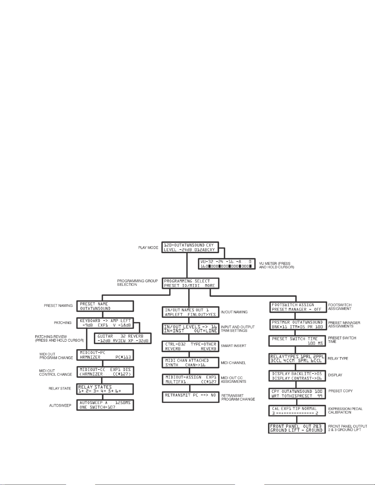
THE MENUS
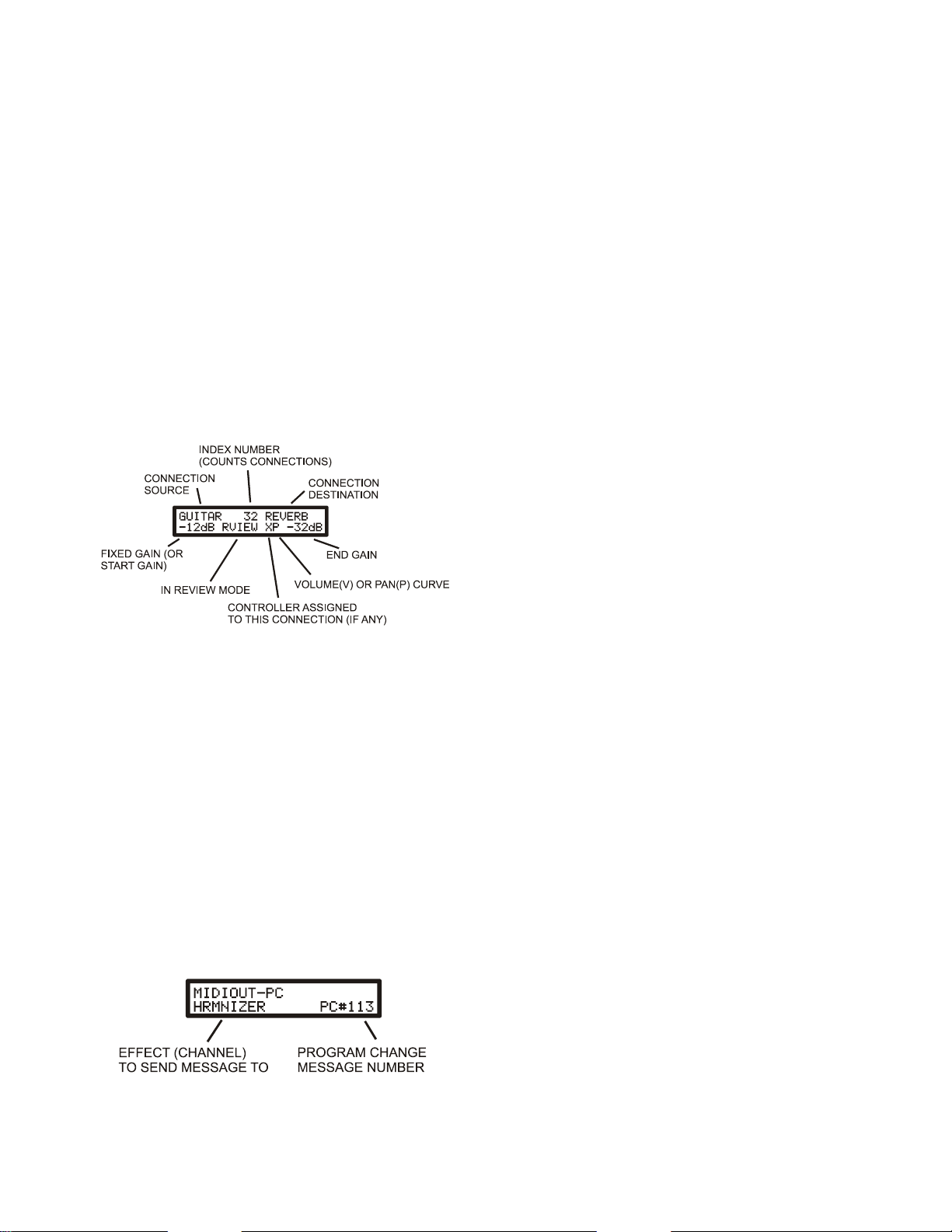
If the MENU switch is pressed from play mode (green LED), the Programming Group Selection Menu is displayed showing the
names of the 3 programming groups. These are the Preset Programming Group (PRESET), the I/O naming and MIDI Setup
Group (IO/MIDI) and the Additional Functions group (MORE). Use the CURSOR switch to choose the desired group and then
press the MENU switch to move to the first menu in that group. Use the MENU switch to move from menu to menu. Each
group of menus will be covered in this section.
11
THE PLAY, PROGRAM SELECT, AND VU MENUS
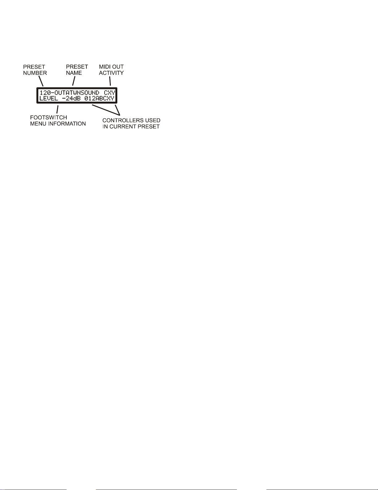
THE PLAY MENU
The play menu is displayed during normal playing and shows whenever the green PLAY LED is lit. If the red PROG LED is lit,
you can always return to the play menu by successively pressing the MENU button until the green LED lights. This menu
displays:
•PRESET NUMBER: The preset number from 1-120. Presets can be selected using the UP/DOWN switches, via MIDI
using Program Change messages, or from a footswitch
•PRESET NAME: The name given to the preset in the Preset Naming Menu.
•FOOTSWITCH MENU INFORMATION: Shows the current footswitch menu and relevant information
•MIDI OUT ACTIVITY: If Autosweep C, Expression pedal 1, or Expression pedal 2 is transmitting MIDI CC
information out the MIDI OUT port then C, X, and/or Y will show up in the upper right corner.
•CONTROLLERS USED IN CURRENT PRESET: Up to 8 controllers can be assigned to any connections in the preset
and the controllers that are used in the preset are displayed here giving a visual indication of what controllers will affect
the sound. These controllers include MIDI Control Change (CC) messages, the 3 internal Autosweeps (LFO), or the 2
expression pedal inputs.
The lower left side of the display shows footswitch information. When used with an optional 3 button footswitch several
functions can be called up and this part of the display shows the current function of the footswitch. Pressing the MODE button
on the footswitch changes to the next menu item. There are 8 functions available which are described in the FOOTSWITCH
ASSIGN menu under the MORE section.
1. PRESET SCROLL- When this function is selected the display shows: PRESET DN/UP and the user can scroll through
the presets using the DOWN or UP switch on the footswitch.
2. PRESET MANAGER- When this function is selected the display shows: BNKxx ITMxx which represent the currently
selected bank number and currently selected item number in the Preset Manager (see Preset Manager in the MORE
section). The bank number can be incremented by pressing the DOWN button on the footswitch and the item number
can be incremented using the UP button on the footswitch.
3. BOOST/CUT - When this function is selected the display shows: BOOST -xxdB where the xx is a dB value
representing the highest gain of any of the connections that are considered final output connections (see INPUT
OUTPUT NAMING MENU). This function differs from the PRESET LEVEL function in that this is a temporary
performance gain change, and the change is not saved to memory. Each time the UP or DOWN button on the
footswitch is pressed the gain changes up or down by 3dB. This is a great way to temporarily change the overall level
in a preset without changing the mix. When the preset is selected again, the gain reverts back to the gain originally
programmed into the preset.
4. AUTOSWEEP TAP TEMPO - When this function is selected the display shows AUTOSWEEP-x where x is one of the
internal Autosweeps (A, B or C) representing the 3 Autosweep oscillators or the letter X representing all Autosweeps.
Pressing the DOWN button displays the next assigned Autosweep controller letter or the X. The X indicates the tap
tempo will affect all 3 oscillators at once (or however many are assigned to the preset) to make it easy to change the
speed of the Autosweeps without changing their relative sync to each other. The tap tempo affects the Autosweep with
the fastest rate. In the Controller view area (lower right of display) if any of the Autosweeps are used in the preset,
those letters will flash at the Autosweep rates. Only Autosweep controllers assigned SMOOTH will be displayed.
5. RELAY STATE - When this function is selected the display shows the on/off state of each of the 6 available relays.
The DOWN switch selects the relay to toggle and the UP toggles the relay. A "+" indicates the relay is closed and "-"
indicates it is open.
6. SWITCH GROUP 1 and 2 - When these 2 functions are selected the display shows "S1-S2 1+ 2+" (for group 1) or "S3-
S4 1+ 2+" (for group 2) and these represent four Control Change on/off type messages that can be transmitted to an
external MIDI device if the DOWN (for S1) or UP (for S2) switches are pressed. Group 2 will transmit the S3 and S4
12
Controller messages instead. These 4 buttons can then be used as instant access switches similar to those found on a
MIDI foot controller
7. PRESET LEVEL - When this function is selected the display shows: LEVEL_-xxdB where xx is the dB value
representing the highest gain of any of the connections that are considered final output connections (see IN/OUT
NAMING MENU). This function is similar to BOOST/CUT except the change is permanently written into the preset
and changes are spaced at 1dB instead of 3dB for the boost/cut feature. DO NOT USE THIS TO RANDOMLY
CHANGE GAINS DURING A PERFORMANCE AS THE CHANGE IS WRITTEN IMMEDIATELY TO MEMORY
CHANGING THE PRESET PROGRAMMING. USE IT ONLY TO ADJUST LEVELS (FOR EXAMPLE)
BETWEEN PRESETS TO NORMALIZE THE LEVELS BETWEEN PRESETS.
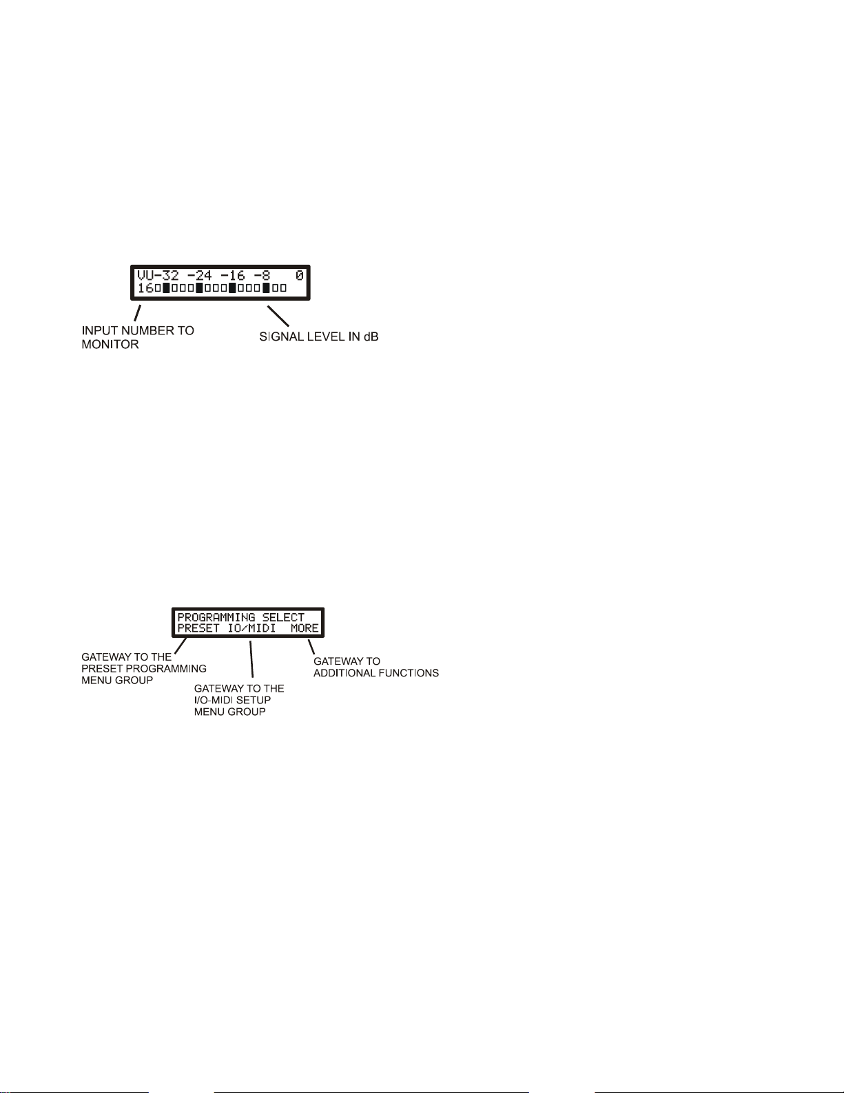
THE VU METER MENU
Press and hold the CURSOR button while in Play mode (green LED lit) to display the VU meter. To exit, press the CURSOR
button again. Select any input or output to monitor using the UP/DOWN buttons. The front panel LEDs show which input or
output is being monitored. The number in the lower left first shows 1-16 (for inputs), then 1-16 (for outputs). 0dB represents the
maximum level before clipping. Each bar represents 2dB. Note that the VU represents the level relative to clipping only and
does not represent dBv levels for example.
The settings of the input and output trims (see INPUT-OUTPUT LEVELS SELECT section) will affect the levels seen as the
input is monitored after the trim on the input side, and after the output trim on the output side. This is a great way to determine
the best trim settings for different devices. For example, if you have a line level device feeding an input and the VU shows
overload (0dB), then the input for that device needs to be changed from INST to LINE setting. Likewise, if a signal seems too
low on an output, you may need to change the output trim from INST (which cuts the signal) to LINE to get a larger output
signal level.
THE PROGRAMMING TREE SELECTION MENU
NOTE: THE PRESET TO BE PROGRAMMED MUST FIRST BE SELECTED WHILE STILL IN PLAY MODE (green LED)
BEFORE MOVING ON TO THE PROGRAMMING GROUP SELECTION MENU.
This menu is the first menu displayed after the Play Menu when the MENU button is pressed and determines which of the 3
programming groups to move into.
•THE PRESET GROUP: The cursor defaults to this selection when entering this menu to give you fast access to the first
menu in the preset group. This group contains all the menus to program a single preset.
•THE IO/MIDI GROUP: This (global functions) group has the input/output naming menu and all menus related to MIDI
functions
•THE MORE GROUP: More global functions such as copying presets, setting up the Preset Manager and so on.
NOTE: WHEN THE CURSOR IS UNDER THE "PRESET" LABEL, PRESSING THE UP AND DOWN SWITCH
TOGETHER (CLEAR FUNCTION) WILL INITIALIZE ALL PARAMETERS IN THE CURRENT PRESET. This means
setting the name to NO NAME XXX, turning off all connections, clearing out all MIDI out messages, turning off the relays, and
turning off the Autosweep.

13
THE PRESET MENU GROUP
PRESET NAME MENU:
Use this menu to give the preset a name of up to 12 characters. The available characters are A-Z, 0-9 and some symbols.
You can clear the entire name row by pressing the UP and DOWN switch together (clear function). No other preset parameter is
affected, only the name of the current preset is cleared.
Use the DOWN or UP/DOIT switch to change the characters and use the CURSOR switch to move to the next character
location.
THE PATCHING MENU:
This menu is the one you will most often use when creating presets as this is where you create input to output connections and
set fixed gains for those connections, or optionally, set both a "start" gain and "end" gain which define a range of gains that can
be controlled by one of several types of controllers. Up to 8 different controllers can be used within a preset, each controlling
one or more connections. Since the start and end gains of each connection can be set to anything, a single controller assigned to
different connections can affect those connections to different degrees. The available controllers are external MIDI controllers,
any of the 3 internal "Autosweep" LFOs, or any of the 2 expression pedal inputs. Any controller can also be assigned with a
volume curve, useful when doing volume swells, or a pan curve which is useful for cross fading between effects or panning
across amplifiers. The curve type is indicated with a "V" or "P" in the display for volume or pan.
1. To create a connection, move the cursor to the upper left area of the display. This is the "source" (where the signal is coming
from). Use the DOWN or UP switch to scroll to the name of the instrument or effect that will be the source of the audio signal.
This will always be an input on the ET.
2. Move the cursor to the upper right area of the display. This is the "destination" area. Use the DOWN or UP SWITCH to
scroll to the name of the amp or effect that the audio signal will be sent to. This will always be an output.
3. Move the cursor to the lower left of the display. This is the gain area used to turn on and set the level of the connection. Use
the DOWN or UP switch to adjust the level. The level can be set anywhere from -48dB to 0dB. The connection is automatically
made when the gain is set anywhere in this range. If set to OFF, the connection is removed. TIP: You can press the DOWN
switch when OFF is displayed and that will get you directly to 0dB. Likewise to turn off a connection when at 0dB press
the UP button and that will turn the connection OFF.
4. If this connection is only to have a fixed gain level (not assigned to a controller to vary the gain) then the cursor may now be
moved back up to the source or destination area to begin selection of the next patch. If this connection is to have a range of
gains, then move the cursor over to the lower right area of the display. A second gain number appears that normally tracks the
first gain value. Press the DOWN or UP switch to set the second gain value different from the first (either higher or lower
including OFF). These two gain values represent the range of gain that this connection will be set to depending on the position
of a continuous controller. To go back to fixed gain, simply scroll until the two gains match, then move the cursor and the
second gain will be removed.
14
5. If a gain range has been set (continuous control), the connection can then be assigned to a controller. The controllers that are
available are MIDI Control Change numbers 0-7 (shown as CC x where x is 0-7), Autosweep A, B or C (shown as ASWPx
where x is A, B or C), and Expression pedal 1 or 2 (shown as EXP1, and EXP2) and these labels will appear in the middle of the
lower row. Move the cursor under this label and use the DOWN/UP buttons to select the controller you want to assign to this
one connection. You can assign the same controller number to several connections if you want a single controller to control
several connections at once.
6. Pressing the CURSOR button will then move the cursor under the letter "V" or "P" which represent the curve that the
controller will follow when moved. If set to "V" the volume will follow a traditional volume curve which is ideal for doing
volume swells. If set to "P" the gain will follow a pan curve. If a signal is sent to 2 amps for example and those 2 connections
are set to a pan curve and with opposing "start" and "end" gains (OFF to 0dB and 0dB to OFF for example) then the sound will
pan evenly between the two amps as the controller is moved.
6. Continue to select source and destination pairs and set gains until the entire preset has been wired up.
7. You can remove all connections in this preset without affecting any other parameters of this preset, by pressing the DOWN
and UP (CLEAR) switches together. A connection that is removed will show OFF in the display for any connection pair that is
displayed. Note that when OFF is displayed, this means there is NO connection between the displayed (source-destination) pair.
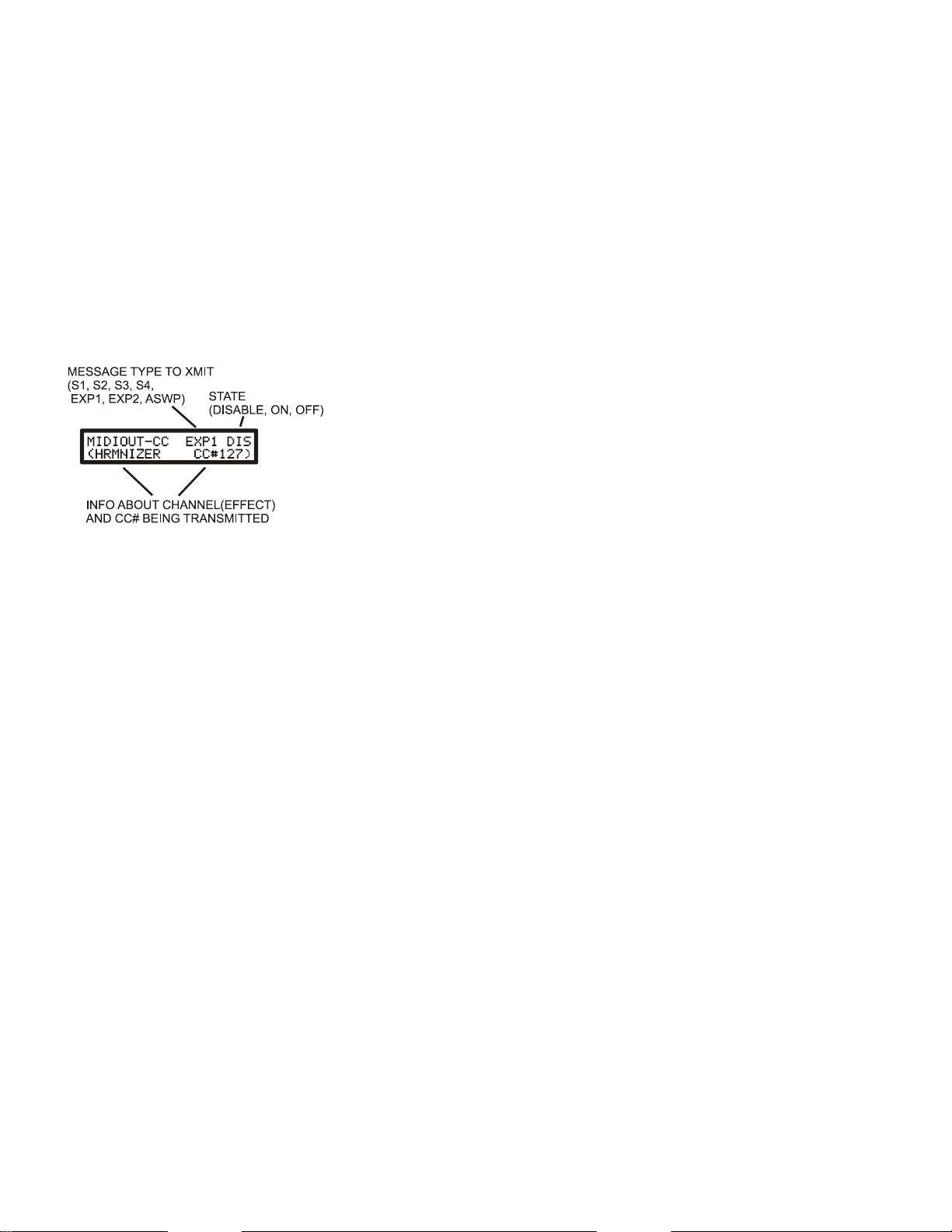
REVIEW MENU:
A convenience menu is available to allow quick review of all the connections and gains that were programmed. The menu
appears the same as the patching menu with the exception that the word "RVIEW" (REVIEW) appears in the 2nd row of the
display.
To enter this menu, press and hold the CURSOR switch while in the Patching Menu. The "RVIEW" word will appear. The
UP/DOWN switches can now be used to scroll through all the connections that were connected. The number in the top row is
simply an index number that counts through the connections as you view them. The source/destination are displayed for each
connection, the gain (or start-end gain pair if a controller is assigned) and a controller (0-7, A-C, or X-Y (for EXP1, 2) if one is
assigned to this connection. Just to the right of the controller letter is the letter "V" or "P" which indicates if a volume or pan
curve is assigned to the connection being reviewed.
To return to the programming menu, simply press the CURSOR switch again. The patch that was shown in the review menu at
the time the CURSOR switch was pressed will be shown in the patching and gain menu to give you fast access to any pair you
might want to edit or delete. No editing can be done in the review menu, to you must exit the review menu to make any changes
to the pair.
THE MIDI OUT PROGRAM CHANGE MENU
NOTE: THIS MENU ONLY APPEARS IF AT LEAST ONE MIDI CHANNEL WAS ASSIGNED TO AN EFFECT NAME
IN THE MIDI CHANNEL MENU (IO/MIDI GROUP) AND ONLY THOSE EFFECTS THAT WERE ASSIGNED A
CHANNEL WILL BE DISPLAYED.
15
Use this menu to transmit a burst of program messages to various MIDI effects when the preset is selected. Up to 16 MIDI
Program change messages can be transmitted over the 16 available MIDI channels.
To use this menu:
1. Move the cursor under the EFFECT name (lower left) and use the UP/DOWN switches to select the effect that you wish
to send a message to.
2. Move the cursor under the PC# (Program Change number) and use the UP/DOWN switches to select the Program
number to transmit to this effect. Scrolling below #0 will display OFF which is used if you do not wish to send a
message to this effect in this preset. Note that as you scroll through program numbers, the numbers are transmitted in
real time to the displayed effect so you can hear the preset you are selecting immediately.
3. Repeat steps 1-2 for each effect you wish to send a PC to.
4. You can quickly set the PC number of an effect to OFF by pressing the UP and DOWN buttons together (clear function)
while the cursor is under the PC# area.
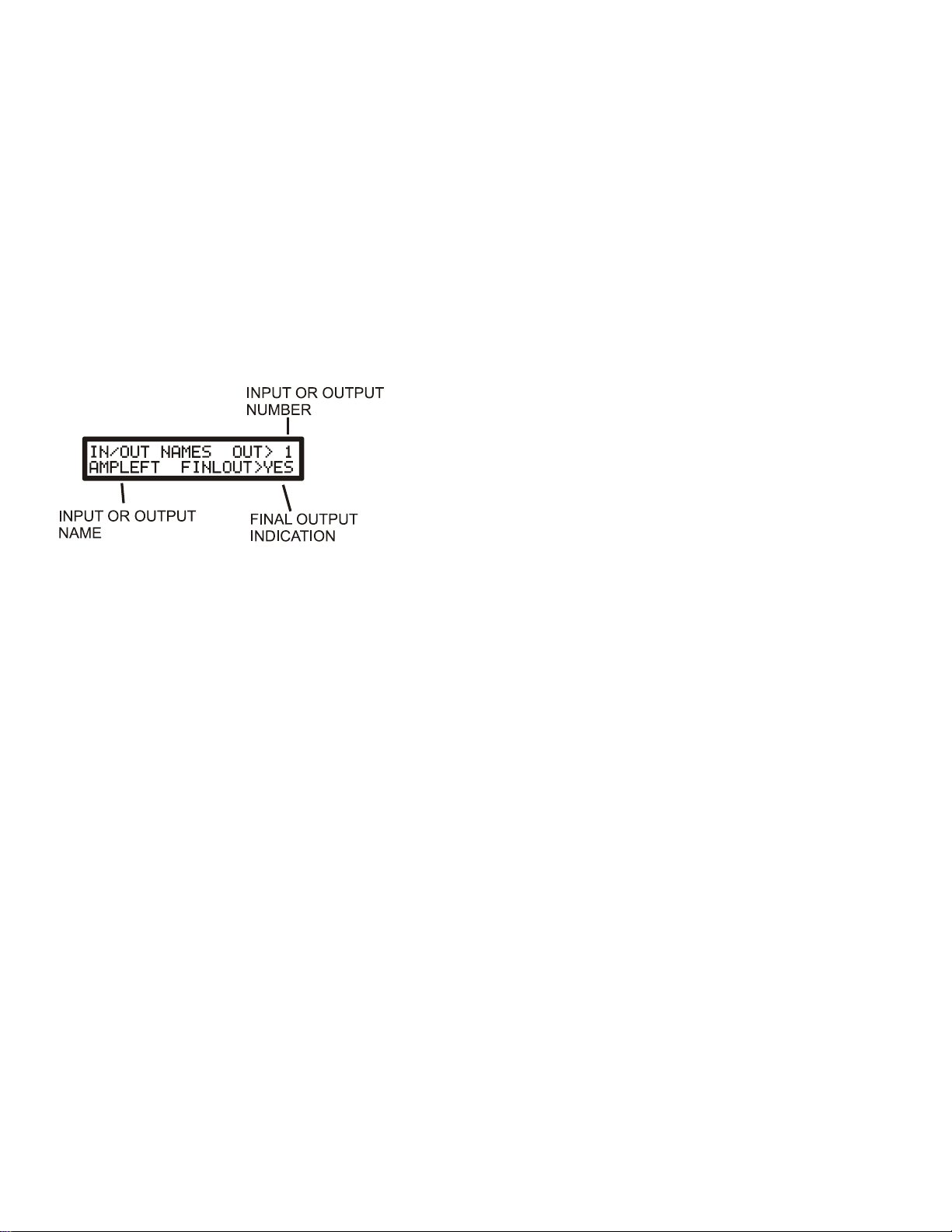
THE MIDI OUT CONTROL CHANGE MENU
NOTE: THIS MENU ONLY APPEARS IF AT LEAST ONE MIDI CHANNEL WAS ASSIGNED TO AN EFFECT NAME
IN THE MIDI CHANNEL MENU (IO/MIDI GROUP) AND ONLY THOSE EFFECTS THAT WERE ASSIGNED A
CHANNEL WILL BE DISPLAYED.
Use this menu to transmit up to 4 MIDI Control Change On/Off style messages to external effects, to transmit continuous
Control Change messages originating from either of the 2 expression pedals or from Autosweep C (only Autosweep C will
transmit a CC message). The MIDI channel (shown as the effect itself) and the CC# to transmit can be set globally so each
preset always transmits the same CC# over the same channel or you can select the effect and CC# on a per preset basis. (See
NOTE below)
To use this menu:
1. Move the cursor under the message type label where the UP/DOWN button can be used to scroll through the 4 available
On/Off messages (labeled S1, S2, S4, and S4), the 2 internal expression pedals (labeled EXP1 and EXP2) or Autosweep
C (labeled ASWP).
2. Move the cursor to the STATE area (upper right) and use the UP/DOWN button to change the state of the selected
label. For S1-S4 you can select ON (transmit on message), OFF (transmit off message) or DIS (disable transmission).
For EXP1, EXP2, and ASWP you can only select ON (transmit the pedal motion) or DIS (disable transmission)
3. For EXP1, EXP2, and the ASWP, if the function is set to ON The data will sweep from 0 to 127 as the pedal is moved
or if the Autosweep is set in the Autosweep menu to One Shot or One-Shot switch. If the Autosweep is set to
SMOOTH, the data will sweep from 0-127 and back to 0 over each cycle.
4. If the "ASSIGN IN PRESET" is selected as is indicated in the note, then you can move the cursor under the effect name
and CC# and select these manually for this preset otherwise you will not be able to edit these two areas.
NOTE: The bottom row displays the effect name and the CC# that is being transmitted for the message type that is currently
being displayed. If the effect name area in the MIDI OUT CC ASSIGNMENTS menu in the IO/MIDI group is set to "ASSIGN
IN PRESET" rather than being set to an effect name, then this area can be edited and an effect can be selected and a CC number
assigned on a preset by preset basis. If instead an effect is selected in the MIDI OUT CC ASSIGNMENTS menu, then this is a
global setting and the effect and CC# cannot be edited here and is shown for informational purposes only to see what is being
transmitted. See the MIDI OUT CC ASSIGNMENTS menu in the IO/MIDI group for more information. In this menu, if a
particular message type has CC# assigned, then the message "(NOT ASSIGNED)" will be displayed instead.

16
RELAY STATES
Use this menu to set the state of each of the 6 relays that control your amp channel or reverb when this preset is selected.
NOTE: THE OUTPUT TYPE (PULSE OR STEADY STATE) MUST BE SELECTED IN THE RELAY TYPE MENU
(SETUP GROUP) TO DETERMINE IF THE RELAY WILL PULSE ONCE OR SIMPLY GO TO AN ON OR OFF STATE
WHEN THE PRESET IS SELECTED. IF X IS SELECTED AS THE TYPE (DIRECT CONTROL ONLY) THEN YOU WILL
NOT BE ABLE TO SET THE STATE OF THE RELAY.
1. Move the cursor under the relay to be set or cleared then use the DOWN/UP switch to turn that relay on or off. A "+" means
the relay is turned on (contact is closed) and "-" indicates it is off (contact open).
NOTE: A preset will set the states of the relays when the preset is selected, but direct control can then be used to change the
state of the relays while in a preset by using the reserved MIDI Control Change numbers.
THE AUTOSWEEP MENU
The Autosweep function is a collection of 3 precision LFOs (Low Frequency Oscillators). Each LFO can be set to a sweep type
and a sweep time. The available types are:
SMOOTH
This is a simple repeating LFO function which sweeps the controller back and forth over the sweep time. The sweep time can be
set from 50ms to 60 seconds per cycle in resolutions of 10ms. This is the type to use for a tremolo effect.
ONE SHOT
When this preset is selected, the sweep is set to the start (representing the starting gain in a connection) then sweeps over the set
time until the end gain is reached at which time it stops sweeping and stays at the end point. The time can be set from 50ms to
60 seconds in 10ms increments.
The sweep may be "fired" over and over with the momentary footswitch by programming the same preset into a single bank of
the Preset Manager. For example, in bank 2, insert the preset into item 1 only. Each time the footswitch is pressed the item
number will reload preset 1 each time the switch is pressed effectively resetting the Autosweep. The same thing can be
accomplished by pressing the same switch on a MIDI foot controller to select the same preset.
ONE SHOT SWITCH (ONE SWITCH)
This is the same as the one shot but when the end of the sweep is reached, the preset changes to the preset selected in the Preset
Number area. There are a number of ways to use this feature. For example, you can set preset 1 to jump to preset 2, and then
have preset 2 jumps back to preset 1 indefinitely. If each preset is programmed so that the 2nd preset has it's starting gains set to
where the 1st preset ends and have the 2nd preset ending gains set to where the 1st preset starts, then you can cycle smoothly
between these 2 presets with no jump in the sound, but with an expanded pallet of times and sounds that you can cycle through.
You can expand this to any number of presets. You can also eventually end the jumping if you wish just by setting the last preset
in the list to One Shot, or Smooth Sweep instead of a One-Shot Switch. This can be very interesting when playing a song where
the sound progresses as the song progresses.
The time for One Shot Switch can be set from 1 second to 60 seconds.
17
NOTE: If you have a preset programmed with a One-Shot Switch and you wish to program that preset, you may find
that when you select the preset with the intention of programming it, the preset will change on you (since that is what
One Shot Switch does). The trick is to select the preset, then immediately press the mode button before the preset
changes. This will pause the switch and allow you to make changes to the preset.
For the Smooth Sweep function only, you can set the sweep time using the Autosweep Tap Tempo function of the footswitch
while in PLAY mode or using the reserved MIDI Control Change numbers as a tap tempo. Each of the 3 LFO units can have
their sweep set independently using a tap tempo while in play mode by selecting the letter that corresponds to the LFO. There is
also a reserved CC to control all 3 in sync. See the appendix for the reserved CC numbers available.
This is the last menu in the Preset Programming Group. Press the MENU switch to return to the PLAY MENU.
THE IO/MIDI MENU GROUP
THE INPUT-OUTPUT NAMING MENU:
This menu assigns names to all instruments, amps, and effects connected to the IN (1-8) and OUT (1-8) jacks. This menu is also
used to identify which outputs are the "final" destinations for a signal, such as an amp or PA system which is described further
below.
To use this menu:
1. Move the cursor under the "IN 1" number. Use the UP/DOWN button to get to the first input that you actually have
something connected to since unconnected inputs and outputs will be left nameless. For example, if you have a guitar plugged
into input 2 but nothing connected to input 1, then skip one and move to IN 2.
2. Move the cursor to the lower left corner and use the UP/DOWN switches to name this input, such as GUITAR or
OVERDRIV. Names can be a maximum of 8 characters in length.
3. Repeat steps 1 and 2 to name all devices that are actually connected to the IN jacks. If you are using stereo effects, then name
each output from the effect a different name such as "EQ LEFT" and "EQ RIGHT".
4. When all IN jacks have been assigned, then begin naming each OUT jack the same way. The "IN xx" label will change to
"OUT 01" if the UP switch is used to scroll past "IN 8". For 1-in, 2-out stereo effects, the input to the effect can be given a
different name than the outputs. For example, the 2 outputs of the EQ device might be named "EQ LEFT" and "EQ RIGHT" but
the input might just be named "EQ". If the device has 2 inputs and 2 outputs, you may give the left in and out the same "EQ
LEFT" name and the same for the right in and out.
TIP: When connecting a mono effect to an input and output, avoid the temptation to add "IN" or "OUT" to the names such as
EQIN and EQOUT. This is not necessary and confusing. Simply give the input and output the same name such as "EQ" AND
"EQ". The Switchblade keeps track of the inputs and outputs and won't let you wire things up the wrong way.
TIP: You can clear out all the characters in a name by pressing both the UP and DOWN switch together when the cursor is
under any character in the effect name area.
5. For outputs only the label FINLOUT> will be displayed. If any outputs go to an amp, PA system, or mixer (in other words is
the final output), then set these connections to YES, otherwise set them to NO. This information is then used by the LEVEL or
BOOST function using either a footswitch connected to the FTSW input or by using reserved Program Change numbers (see the
Appendix for exact numbers). See the FOOTSWITCH ASSIGN MENU for more information about this feature.

18
THE INPUT-OUTPUT LEVELS SETTING MENU
This menu is used to set the trims on each input and each output to either LINE level or INST (instrument) level.
These trims should be set as part of your setup routine before first use if you want to match your gear levels to give you the best
experience with creating sounds. The addition of this feature in the Switchblade ET gives the user the ability to connect both
line level (studio gear) and instrument level (guitar stomp boxes) effects together without dealing with wildly differing levels
between effects. Once you connect your gear, you only need to set this level once, changing it only if you change your gear.
To understand how to best use this feature, it’s good to understand the Switchblade operates at line level internally and the idea
is to simply set the inputs and outputs so internally, everything is talking to everything at the same (line) level while the device
themselves are operating at their native levels. Setting the input to INST boosts an instrument up to line level, while setting the
input to LINE leaves the signal alone. Setting the output to INST level cuts the signal down to a level comfortable for guitar
amps or guitar stomp boxes while setting the output to LINE leaves the signal at line level for connection to line level effects or
DI line level boxes.
In the following example, settings are shown for various devices to give you an idea of how to set the inputs and outputs for your
devices.
Guitar –INST
Line level Keyboard –LINE
Flanger stomp box –INTR on both the input and output the device is connected to.
Rack mounted line level multi-effect unit –LINE on both the input and output the device is connected to.
Amp - INST
Line level DI box - LINE
Now you can combine all these devices together in a preset without having to worry about a signal level mismatch as internally
all signal levels will be at line level, while the devices themselves are operating at the levels they prefer.
The INST level setting boosts the input level by 12dB. The INST level setting on the output cuts the signal level by 12dB. The
line settings on both input and output have no effect on the signal level. Please see the specifications in the appendix for
technical specs on signal levels.
SMART INSERT MENU:
This menu allows the assignment of Control Change numbers (0-127) to be assigned to an input/output pair that make up a
"loop" (an effect device) or to just an input or to just an output. In this way you can use controller numbers while in a particular
preset to remove and re-insert effect devices (loops) into their respective locations in the preset. Since you can also assign
controller numbers to inputs and outputs, you can use this to turn on or off individual instruments and amplifiers without having
to change presets.

19
As this function is comprehensive, please refer to the separate section "Switchblade ET Smart Insert Feature User's Guide" for a
detailed look at this powerful feature.
MIDI CHANNEL ASSIGNMENT MENU:
This menu is used to set the Switchblade MIDI channel number, to assign MIDI channels to any MIDI devices that are connected
to the Switchblade outputs (labeled ATTACHED in the GROUP SELECT area of the display) and also to any MIDI devices
which may not be connected to the Switchblade but which you may wish to control such as effects connected elsewhere in your
system but connected by MIDI (labeled EXTERNAL in the GROUP SELECT area of the display).
To start, move the cursor to the GROUP SELECT area (upper right corner).
To set the Switchblade MIDI channel, use the UP/DOWN switches to scroll through all EXTERN and ATTACHED effect
names until SWBLADE is displayed. Move the cursor to the channel area (CHAN) and use the UP/DOWN switch to select a
channel number for the Switchblade. NOTE: You cannot assign the same channel number to different devices, so if the channel
number you want doesn't show up, this means it's already assigned to another device. Look at your other devices (ATTACHED
and EXTERNAL) to find the device the channel is assigned to and set the channel number to OFF if you want to use the channel
number elsewhere.
To assign a MIDI channel to any MIDI effects that are connected to the Switchblade, in other words, any effects that have
already been given a name in the OUT section of the Input Output Naming Menu (Setup Group), press the UP or DOWN switch
while the cursor in the GROUP SELECT area until the label ATTACHED is displayed. Notice that the NAME OF MIDI
DEVICE area (lower left corner) will display a name from the Input Output Naming Menu. Continue to use the UP/DOWN
switch to move through all the names of devices named in the Input Output Naming Menu until you find a name you want to
associate with a MIDI channel. Move the cursor under CHAN and assign the channel you want for this name. Again, channel
numbers will not show if they were already assigned to another device.
To assign a MIDI channel to a MIDI effect that was not named in the Input Output Naming menu, but that may be located
somewhere else in your system and connected only by MIDI, press the UP or DOWN switch while the cursor in the GROUP
SELECT area until the label EXTERN is displayed. Notice that the NAME OF MIDI DEVICE area (lower left corner) will
initially display (NO NAME). Move the cursor under this area and use the UP/DOWN buttons to create a name that identifies
the device you want to control. This is simply a label that will help you find the device in the MIDI OUT PC or MIDI OUT CC
Menu (Preset Group) when it comes time to transmit MIDI data to the device and serves no other purpose. Once you have
named this external device, move the cursor to the channel (CHAN) area and assign it a channel.
To assign additional external devices, move the cursor back up to the GROUP SELECT, press the UP button once so that
EXTERNAL is displayed and (NO NAME) is also displayed, then repeat the above process to name the second device and so on.
You can assign up to 16 external devices.
At any time you can move the cursor under the GROUP SELECT area and use the UP/DOWN buttons to see the channel
numbers assigned to the Switchblade, all the attached MIDI devices you have assigned a channel to (and any you have not), and
all (if any) externally named devices that you have assigned a channel to.
Table of contents
Other Sound Sculpture Switch manuals


Popular Switch manuals by other brands


CYP
CYP EL-41PIP Operation manual

ANTAIRA
ANTAIRA LMP-0804G-SFP Series Quick installation guide

H3C
H3C S5500-EI series installation guide

Hirschmann
Hirschmann SPIDER 5TX Description and operating instructions

Comnet
Comnet CNGE4US Installation and operation manual

cable matters
cable matters 103081 user manual


