Sound Skulptor EQ573-II User manual

www.soundskulptor.com
Document revision 1.1 – Last modification : 27/05/21
E 573-II Assembly guide
Safety warning
The kits are main powered and use potentially lethal voltages. Under no circumstance should someone undertake the
realisation of a kit unless he has full knowledge about safely handling main powered devices.
Please read the “DIY guide” before beginning.
Print or open the following documents :
•E 573-II Schematics
•E 573-II Components layout
•E 573-II Parts list
Follow this guide from item number 1 till the end, in this order. The assembly order is based on components height, from
low to high profile, in order to ease the soldering process : The component you are soldering is always taller than the
previously assembled ones and it is pressing nicely against the work area foam.
Soldering
All the PCB holes are metallized. It means the connection between the top and bottom pads is already
done. The parts must be soldered only from below (unless differently stated).
Use only small diameter solder, 0.5 or 0.7 mm, 1mm maximum. Use the minimum possible amount of
solder. Bad joints are almost always caused by too much solder.
Cut the component leads and pins totally flush with the PCB after soldering. A too long tail could create
an electric connection with the side plate.
Here are two excellent introduction to soldering videos:
http://www.eevblog.com/2011/06/19/eevblog-180-soldering-tutorial-part-1-tools/
http://www.eevblog.com/2011/07/02/eevblog-183-soldering-tutorial-part-2/
E 573-II Assembly guide – Main board
1. PCB split
Split the PCB into 4 parts along the grooves.
Use extra thin sandpaper to polish all the rough
sides.
Copyright ©2020 to today SoundSkulptor
www.soundskulptor.com
Document revision 1.1 – Last modification : 27/05/21
E 573-II Assembly guide – Main board
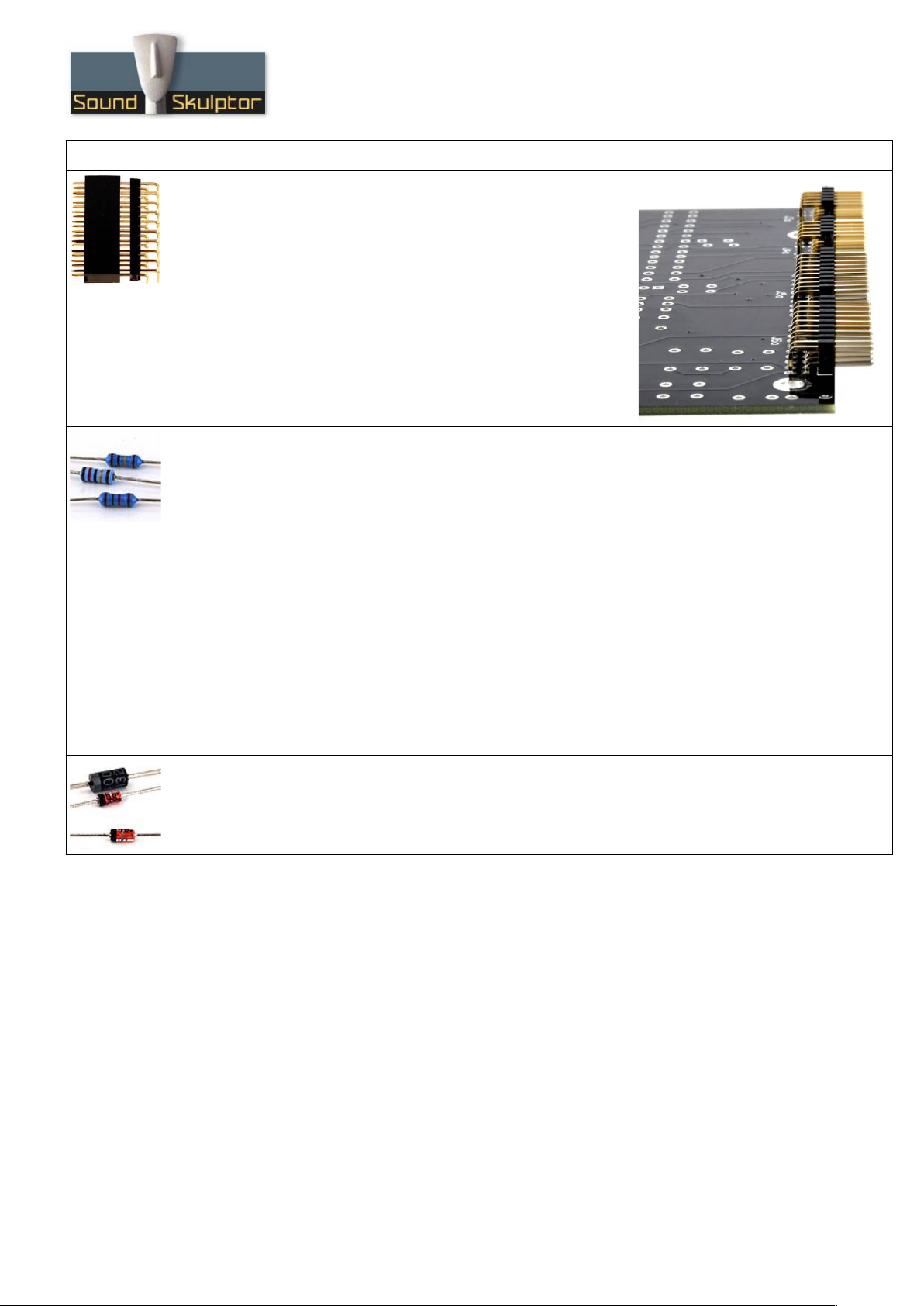
2. PCB to PCB connector J3a, J4a, J5a, J6a
Insert the male 2x10 and 2x5 connectors into the corresponding
female parts and position them on the main PCB back. The female
connectors must sit flat on the side. Solder two pins, check
position then solder the other pins.
After soldering you can remove the female part.
Warning : These connectors are inserted at the back of the PCB
and soldered on top.
3. Resistors
The best method to select and install the resistors is the following:
1. pick a row of resistors in the resistors bag,
2. Measure one of the resistors with your DMM,
3. Look up the parts-list PDF for the closest value,
4. Check the color code and quantity for confirmation,
5. Use the search function on the Layout PDF page with the resistor value: All the corresponding
resistors are highlighted,
6. Insert and solder.
(You can use the same method later, for the capacitors)
Add all the resistors of the main PCB (black identifier in the parts list).
Control the resistor values with a digital multimeter. Bend the leads at 0.4” with a lead forming tool.
Warning : It is very important to check the resistors value with a DMM because the color code can
sometimes be ambiguous. For example 1kΩ (brown-black-black-brown-brown) can be confused with 110Ω
(brown-brown-black-black-brown).
4. Diodes
Add D1 to D4. Use a lead forming tool to bend the leads at 0.4”.
Warning : Make sure to respect the direction of the diodes which is marked by a ring on the component
and a double line on the PCB marking.
Copyright ©2020 to today SoundSkulptor

www.soundskulptor.com
Document revision 1.1 – Last modification : 27/05/21
E 573-II Assembly guide – Main board
5. Ceramic capacitors
Add the ceramic capacitors.
6. IC Socket
Insert and solder the two 8 pins socket.
Warning : Make sure to respect the socket direction, marked by a notch.
7. Relay
Add RLY1 and RLY2.
Warning : Make sure to respect the direction of the relays which is marked by a white line on the
component and on the PCB marking.
8. Film capacitors
Add the film capacitors of the main PCB (black identifier in the parts list).
Copyright ©2020 to today SoundSkulptor

www.soundskulptor.com
Document revision 1.1 – Last modification : 27/05/21
E 573-II Assembly guide – Main board
9. Test pins
Solder the 7 test pins TP1, TP2, TP3, TP4, 0V, V+, V-.
10. Tantalum capacitors
Add C61, C69. The plus lead is the longest.
Warning : The +lead must go into the +hole. Do not reverse !
11. Transistors
Add 1 to 6.
Warning : Watch out the transistor direction.
12. Non polarized electrolytic capacitors
Add C9, C10, C11, C12.
These caps are not polarized and can be inserted in any direction.
Copyright ©2020 to today SoundSkulptor

www.soundskulptor.com
Document revision 1.1 – Last modification : 27/05/21
E 573-II Assembly guide – Main board
13. Electrolytic capacitors
Add all the other electrolytic capacitors of the main PCB.
Warning : The +lead must go into the +hole. Do not reverse (they may explode !)
14. Link Connector J2
Solder the connector header J2. Solder one pin first, check verticality, then solder the other pins.
Warning : Check the direction.
15. Inductors
Solder L1 and L2.
16. U1, U2
Insert the two integrated circuits U1and U2 into their respective sockets.
Warning : these two parts are different and have a direction identified by a notch or a dot.
Copyright ©2020 to today SoundSkulptor

www.soundskulptor.com
Document revision 1.1 – Last modification : 27/05/21
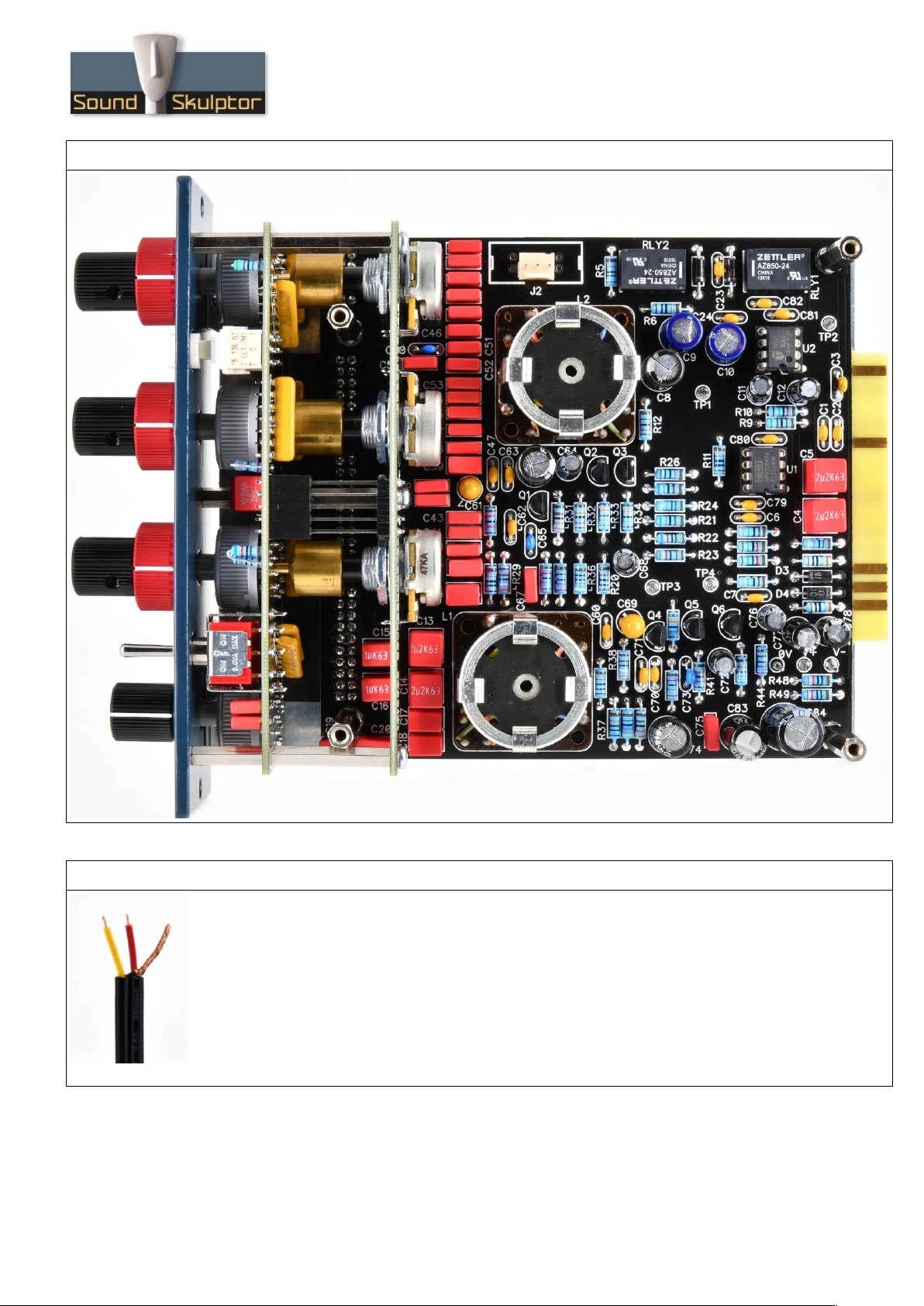
E 573-II Assembly guide – Main board
17. Visual check
At this point, brush the solder side with a hard tooth brush to remove any remaining solder bits.
Make a full visual check. Any missing component on the board ? Any remaining component in the box ?
When everything looks correct, proceed with the other boards assembly.
E 573-II Assembly guide – Switches board
18. Anti-clic resistor networks
Insert and solder 8 resistor networks at the back of the PCB. These parts are all the same but have a
direction.
Warning : Check the direction which is identified by a dot on the part and on the PCB.
19. Film capacitors
Add the film capacitors of the switch PCB (blue identifier in the parts list).
20. Resistors
All the resistors are inserted vertically.
Add the resistors of the switch PCB (blue identifier in the parts list).
21. Push switches
Insert the push switch SW5, flat on the PCB, in the correct direction and solder one pin. Check again
the good position then solder the other pins.
Warning : The switch direction is given by the digits 2 0 1, engraved on one side of the switch. Match
the digits with the ones on the PCB.
Insert the switch cap.
Copyright ©2020 to today SoundSkulptor
www.soundskulptor.com
Document revision 1.1 – Last modification : 27/05/21
E 573-II Assembly guide – Switches board
22. 12 positions Rotary switch
Add the 12 positions rotary switch SW6.
Warning : The position of the switches is critical for a good front-plate matching and a smooth
potentiometer rotation. The switch rests on 3 small feet that must sit perfectly flat on the PCB. Press
the switch on the PCB and solder two opposed pins. Check position then solder the other pins.
23. 6 positions rotary switches
Select the switch with the longest shaft (20 mm) and add it in SW1.
Next, add SW3 and SW4 (15mm shaft).
Warning : Do not mix the 20mm and 15mm shaft rotary switches
24. Toggle switches
Add the toggle switch SW2.
Warning : The position of the switches is critical for a good front-plate matching. It must sit flat on the
PCB. Press firmly the switch on the PCB and solder two opposite pins (housing). Check position then
solder the other pins.
25. Connectors J3b, J4b, J5b, J6b
Solder the two 2x10 and two 2x5 female connectors on the back of the PCB, inserted from the solder
side.
Warning : Be very careful not to touch any other component with your iron tip while soldering.
26. Spacers
Insert three M2.5x25mm male/female spacers from the solder side
of the PCB and attach with three M2.5x15mm spacers.
Copyright ©2020 to today SoundSkulptor

www.soundskulptor.com
Document revision 1.1 – Last modification : 27/05/21
E 573 Assembly guide – Potentiometers board
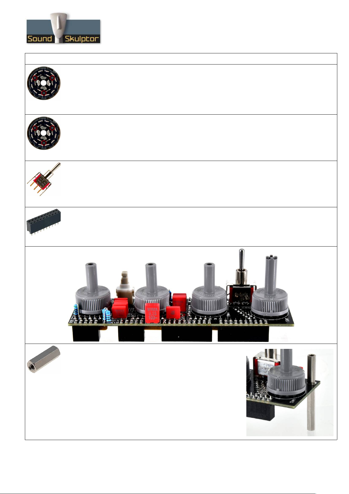
27. Resistor
Add the resistor R17 horizontally (green identifier in the parts list).
28. Potentiometers
Add P1 and P3 (10KA). Insert the potentiometers into the PCB holes from the solder side, making sure
the pins fit into the corresponding PCB pads. Attach with washer and nut on the components side, then
solder.
Add P2 (47KA) in the same way.
29. 2x5 pins connector J7a
Insert and solder 2x5 pins header.
Warning : Make sure to sit them perfectly flat on the PCB for a good position match with the switches
board.
30. Shaft adapters
Insert the three shaft
adapters on the three
potentiometers. Attach
with three headless
screws.
E 573 Assembly guide – Final assembly
31. Switch board and potentiometer board assembly
Insert the potentiometer shafts into the rotary switches hollow shafts, taking care of the connector
matching. Attach with three M2.5x8mm screws.
Copyright ©2020 to today SoundSkulptor

www.soundskulptor.com
Document revision 1.1 – Last modification : 27/05/21
E 573 Assembly guide – Final assembly
32. Front panel assembly
Insert and attach the front panel with three M2.5x8mm black screws.
33. Chassis plate assembly
Attach the chassis plate to the front plate with two M3x6mm black screws.
34. Main PCB assembly
Insert the main PCB connectors into the switch PCB connectors.
Screw four nuts to the four M3x25mm spacers and use them to attach the main PCB to the chassis
35. 19mm red knobs
Set all the rotary switches fully anti-clockwise.
Place the three 19 mm red knobs on the three top switches, lining up the white lines to the “off” labels.
Tighten very gently the screws with the supplied 1.5mm hex key.
Warning : To not tighten too hard in order not to warp the switch shaft.
36. 12.7mm buttons
Set all the potentiometers to 12 o'clock. You must feel the centre click in this position.
Insert the three 12.7mm black knobs into the three top switches, lining the white lines vertically.
Tighten the two screws with the supplied 1.5mm hex key.
Attach the last knob to the lowest rotary (high pass), lining up the white line to the “off” label.
37. Cover
Attach the cover with 4 M3x6mm countersunk screws.
38. Congratulations
You're done!
Copyright ©2020 to today SoundSkulptor
www.soundskulptor.com
Document revision 1.1 – Last modification : 27/05/21
E 573 Assembly guide – Final assembly
E 573 Assembly guide – Link cable assembly (for connecting to MP573)
39. Cable striping
Split the 2 sections of the wire on a length of 2.5cm.
Strip 1.5cm of each section.
Merge the shield wires from the 2 sections and twist, red in the middle.
Strip red and yellow wires on 2mm.
Copyright ©2020 to today SoundSkulptor

www.soundskulptor.com
Document revision 1.1 – Last modification : 27/05/21
E 573 Assembly guide – Link cable assembly (for connecting to MP573)
40. Connectors soldering
If you own a crimping tool, crimp a contact on each wire.
If not, tin the wire tips and solder a contact to each wire.
41. Plug insertion
Insert 2cm of heat-shrink tube on the wire.
Insert the plug on the 3 contacts, taking care to respect the colour positions.
42. Second connector
Repeat the same operations identically at the other end of the cable.
43. Tube shinking
If you own a hot-air gun, quickly blow some hot air on the two tubes to make them shrink.
Copyright ©2020 to today SoundSkulptor
Table of contents
Other Sound Skulptor Stereo Equalizer manuals


