Sound Skulptor EQ573 User manual

www.soundskulptor.com
Document revision 1.1 – Last modification : 01/05/14
EQ5 3 Assembly guide
Safety warning
The kits are main powered and use potentially lethal voltages. Under no circumstance should someone undertake the
realisation of a kit unless he has full knowledge about safely handling main powered devices.
Please read the “DIY guide” before beginning.
Print or open the following documents :
•EQ5 3 Schematics
•EQ5 3 Components layout
•EQ5 3 Parts list
•EQ5 3 Setup guide
Follow this guide from item number 1 till the end, in this order. The assembly order is based on components height, from
low to high profile, in order to ease the soldering process : The component you are soldering is always taller than the
previously assembled ones and it is pressing nicely against the work area foam.
EQ5 3 Assembly guide – Main board
1. Diodes
Add D1 to D5. Use a lead forming tool to bend the leads at 0.4”.
Warning : Make sure to respect the direction of the diodes which is marked by a ring on the component
and a double line on the PCB marking.
2. Resistors
Add R1 to R66.
Control the resistor values with a digital multimeter. Bend the leads at 0.4” with a lead forming tool.
3. Test pins
Solder the 5 test pins TP1 to TP5.
4. Ceramic capacitors
Add C 9, C8 .
5. Film capacitors
Add C24 to C49, C51, C53 to C55, C5 to C 5, C80, C81, C84, C88, C89, C92.
Copyright ©2011 to today SoundSkulptor

www.soundskulptor.com
Document revision 1.1 – Last modification : 01/05/14
EQ5 3 Assembly guide – Main board
6. Tantalum capacitors
Add C 8, C86. The plus lead is always on the right when facing the marking with the leads pointing
down.
Warning : The +lead must go into the +hole. Do not reverse !
. Connector
Solder the 2 x 8 pins header CN3A. Solder one pin first, check verticality, then solder the other pins.
8. SIL connector
Solder the connector socket CN4A. Solder one pin first, check verticality, then solder the other pins.
9. Transistors
Add Q1 to Q6.
Warning : Watch out the transistor direction.
Copyright ©2011 to today SoundSkulptor

www.soundskulptor.com
Document revision 1.1 – Last modification : 01/05/14
EQ5 3 Assembly guide – Main board
10. Relays
Add RLY1 and RLY2.
11. Electrolytic capacitors
Add C19 to C23, C 6, C , C82, C83, C85, C90, C91, C93 to C96.
Solder one lead first, adjust verticality then solder the second lead.
Warning : The +lead must go into the +hole. Do not reverse (they may explode !)
12. Inductors
It is necessary to leave a small gap between the inductors and the PCB surface in order to avoid any
electrical contact between the metal parts and pads. Fit a piece of double sided adhesive tape (supplied
with the kit) on the inductor, between the pins. It is not necessary to remove the second protective
layer from the tape as it is only used as a spacer.
Solder L1 and L2.
Copyright ©2011 to today SoundSkulptor

www.soundskulptor.com
Document revision 1.1 – Last modification : 01/05/14
EQ5 3 Assembly guide – Main board
13. Visual check
At this point, brush the solder side with a hard tooth brush to remove any remaining solder bits.
Make a full visual check. Any missing component on the board ? Any remaining component in the box ?
When everything looks correct, proceed with the other boards assembly.
EQ5 3 Assembly guide – Switches board
14. PCB split
Split the PCB along the pre-engraved lines in order to get 3 parts. You can
polish the cut with a file.
15. PCB split (continued)
Separate the 2 tiny PCB's from the larger PCB's and smooth out the cuts
with a file or sand paper.
16. Anti-clic resistors
Insert and solder 43 4M resistors. The resistors are placed vertically.
1 . Rotary switches
Add the 12 positions rotary switch SW4.
Warning : The position of the switches is critical for a good front-plate matching and a smooth
potentiometer rotation. The switch rests on 3 small feet that must sit perfectly flat on the PCB. Press
the switch on the PCB and solder two opposed pins. Check position then solder the other pins.
Add the other three, 6 positions switches SW1, SW2 and SW5 in the same way.
18. Toggle switches
Add the two toggle switches SW3, SW6.
Warning : The position of the switches is critical for a good front-plate matching. They must sit flat on
the PCB. Press firmly the switch on the PCB and solder two opposite pins (housing). Check position then
solder the other pins.
Copyright ©2011 to today SoundSkulptor

www.soundskulptor.com
Document revision 1.1 – Last modification : 01/05/14
EQ5 3 Assembly guide – Switches board
19. Pin header
This part requires some care and you will need a good soldering iron
with a thin tip.
Insert the 2x40 pins header, straight pins forward from the solder
side, as shown on the diagram. Make sure it sits perfectly flat on the
PCB. Solder 2 extreme pins and adjust the position if needed. Solder
one more pin around the centre, while pressing it down on the PCB.
Now solder all the pins on the external row. Cut the soldered pins
flush, in order to get access to the second row. Solder the second
row then cut the pins flush.
Warning : The position of the header is very important to the final assembly. Do not overheat when
soldering because if the black plastic base melts, the pins are no longer held in position.
EQ5 3 Assembly guide – Potentiometers board
20. CN2 Connector
Solder the 3 pins header in the 3 right holes (circled in red
on the picture). The plastic tab is on the left. Solder one
pin first, check position then solder the other pins.
21. Connector
Solder the 2x8 pins header. Solder one pin first, check position then solder the other pins.
22. Potentiometers
Add P1 and P3 (10KA). Insert the potentiometers into the PCB holes from the components side, making
sure the pins fit into the corresponding PCB pads. Attach with washer and nut on the solder side, then
solder.
Add P2 (4 KA) in the same way.
Copyright ©2011 to today SoundSkulptor

www.soundskulptor.com
Document revision 1.1 – Last modification : 01/05/14
EQ5 3 Assembly guide – IO board
23. Resistors
Add R1 to R16.
Control the resistor values with a digital multimeter. Bend the leads at 0.4” with a lead forming tool.
24. Ceramic capacitors
Add C1, C2, C , C8, C10.
25. IC Sockets
Insert and solder the 8 pins sockets of UI and U2. Do not insert U1 at this time.
Warning : Make sure to respect the socket direction, marked by a notch.
26. Electrolytic capacitors
Add C9, C11, C12, C15 to C18, C13, C14, C3 to C6.
Solder one lead first, adjust verticality then solder the second lead.
Warning : The +lead must go into the +hole. Do not reverse (they may explode !)
2 . Connector
Solder the connector CN4B. Solder one pin first, check verticality, then solder the other pins.
Warning : the connector pins must be exactly perpendicular to the PCB to allow proper insertion into the
main board.
28. IC's
Insert U1 and U2 in their respective socket.
EQ5 3 Assembly guide – Final assembly
29. Front pannel assembly
Attach the 15mm female/female spacer to the front panel with
an M3x6 countersunk black screw.
Next, insert the switches into the front panel and attach the
switches board to the 15mm spacer with one M3x6 screw.
Copyright ©2011 to today SoundSkulptor

www.soundskulptor.com
Document revision 1.1 – Last modification : 01/05/14
EQ5 3 Assembly guide – Final assembly
30. Side panel
Attach the side panel to the front plate with two M3x6 black
countersunk screws.
31. Main PCB
Install the main PCB on the side panel, inserting the 2x40 pins header into the PCB holes. Attach it with
two M3x6 screws and two shake-proof washers in the front and two M3x20 male/female spacers in the
back.
32. Header soldering
Solder the header's 2x40 pins that link the two PCB's, starting with the row that is close to the PCB
edge. Cut flush 4 or 5 pairs of pins near the centre of the header, where a spacer will be installed.
33. 25mm Spacers
Remove the front panel by unscrewing
three M3x6 black screws.
Attach three 25mm spacers to the
switches PCB, on the solder side, with
three M3x6 screws.
34. Potentiometer 6/4mm shaft adapters
On the potentiometers PCB, set all three pots
fully clockwise. Insert the three 6mm/4mm
adapters all the way down, with the screws
facing towards the PCB edge that carries the
two connectors. Tighten the screws.
35. Potentiometer 4/3mm shaft adapters
While keeping the pots in their full clockwise position, insert the three
4mm/3mm adapters with their slot perpendicular to the screw (facing up).
Tighten gently, just enough to hold them into position.
Copyright ©2011 to today SoundSkulptor

www.soundskulptor.com
Document revision 1.1 – Last modification : 01/05/14
EQ5 3 Assembly guide – Final assembly
36. Potentiometers PCB assembly
Attach the potentiometers PCB to the
switches PCB with three M3x6 screws.
Do not tighten yet.
Attach the front panel again with three
M3x6 black countersunk screws.
3 . 15mm buttons
Set all the rotary switches fully anti-clockwise.
Attach the three “pass through” buttons to the three top switches, lining up the white lines to the “off”
labels.
Attach the screw type button to the lowest rotary (high pass), lining up the white line to the “off” label
and clip on the red cap.
38. 10mm buttons
Attach the 3mm shafts to the 10mm buttons and clip on
the button caps.
Make sure the potentiometers are still set fully clockwise. Insert the shafts into the centre holes while
lining up the white line to the “Max” dots on the front panel. Tighten the screws on the shaft adapters.
If the pots feel a little hard to turn, blow a drop of contact cleaner inside the potentiometers.
39. PCB tightening
Tighten the 3 screws that attach the potentiometers board.
40. I/O board assembly
Insert the 10 pins header from the I/O board into the
corresponding socket on the main PCB. Attach the board to
the 20mm spacers with two M3x6 screws.
41. Ribbon cable
Connect the 16 conductors ribbon cable between the pots and
the main PCB.
42. Congratulations
You're done!
Copyright ©2011 to today SoundSkulptor

www.soundskulptor.com
Document revision 1.1 – Last modification : 01/05/14
EQ5 3 Assembly guide – Final assembly
EQ5 3 Assembly guide – Link cable assembly (for connecting to MP5 3)
1. Connector soldering
Insert the 3 pins female connector
into the second row of holes (circled
red). You can add a drop of instant
glue between connector and PCB to
improve reliability. And solder.
Repeat for the second PCB.
2. Cable striping
Split the 2 sections of the wire on a length of 3cm.
Strip 2cm of each section.
Merge the shield wires from the 2 sections and twist, red in the middle.
Strip red and yellow wires on 4mm.
Tin the wire tips to keep them together, with very little solder or they won't fit into the PCB holes.
Copyright ©2011 to today SoundSkulptor
www.soundskulptor.com
Document revision 1.1 – Last modification : 01/05/14
EQ5 3 Assembly guide – Link cable assembly (for connecting to MP5 3)
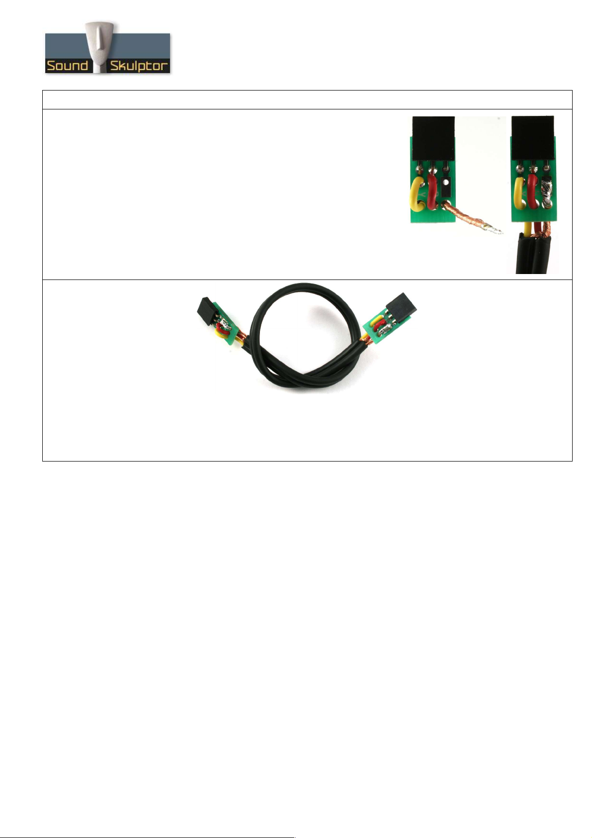
3. Cable soldering
Insert the cable 3 wires from beneath the PCB into the 3 unplated
holes, red in centre, yellow on the “Y” side. Insert the red and
yellow wire tips into the corresponding PCB holes and solder.
Cut the shield cable to the good length, flatten it on the
rectangular pad and solder.
Repeat for the other side of the cable.
Copyright ©2011 to today SoundSkulptor
Other manuals for EQ573
2
Table of contents
Other Sound Skulptor Stereo Equalizer manuals


