Sound Skulptor SK99 User manual

www.soundskulptor.com
Document revision 1.1 – Last modification : 10/08/17
SK Assembly guide
Safety warning
The kits are main powered and use potentially lethal voltages. Under no circumstance should someone undertake the
realisation of a kit unless he has full knowledge about safely handling main powered devices.
Please read the “DIY guide” before beginning.
Print or open the following documents :
• SK Schematics
• SK Components layout
• SK Parts list
Follow this guide from item number 1 till the end, in this order. The assembly order is based on components height, from
low to high profile, in order to ease the soldering process : The component you are soldering is always taller than the
previously assembled ones and it is pressing nicely against the work area foam.
SK Assembly guide
1. Soldering
All the PCB holes are metallized. It means the connection between the top and bottom pads is already
done. The parts must be soldered only from the bottom side (unless differently stated).
Use only small diameter solder, 0.5 or 0.7 mm, 1mm maximum. Use the minimum possible amount of
solder. Bad joints are almost always caused by too much solder.
Here are two excellent introduction to soldering videos:
http://www.eevblog.com/2011/06/1 /eevblog-180-soldering-tutorial-part-1-tools/
http://www.eevblog.com/2011/07/02/eevblog-183-soldering-tutorial-part-2/
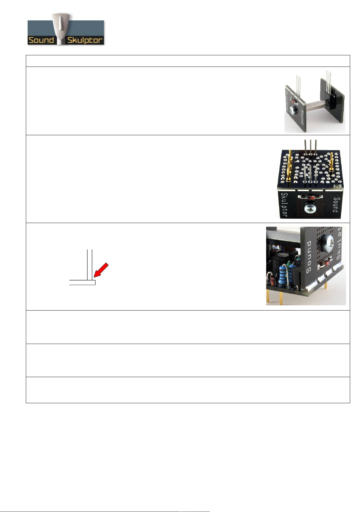
2. PCB split
Split the PCB into 3 parts along the lines shown by the red arrows.
3. Pins
Insert and solder the 6 golden pins. The pins are inserted from below the
PCB.
The best solution to keep the pins perfectly perpendicular is to use the final
host PCB (like the MP512, MP5 ) as a guide: Insert the 6 pins into the
1mm sockets of the receiving PCB, position the DOA PCB over the pins and
solder.
It is a good idea to protect the golden pins with some wire insulating sleeve
before doing other component soldering.
Copyright ©2014 to Today SoundSkulptor
www.soundskulptor.com
Document revision 1.1 – Last modification : 10/08/17
SK Assembly guide
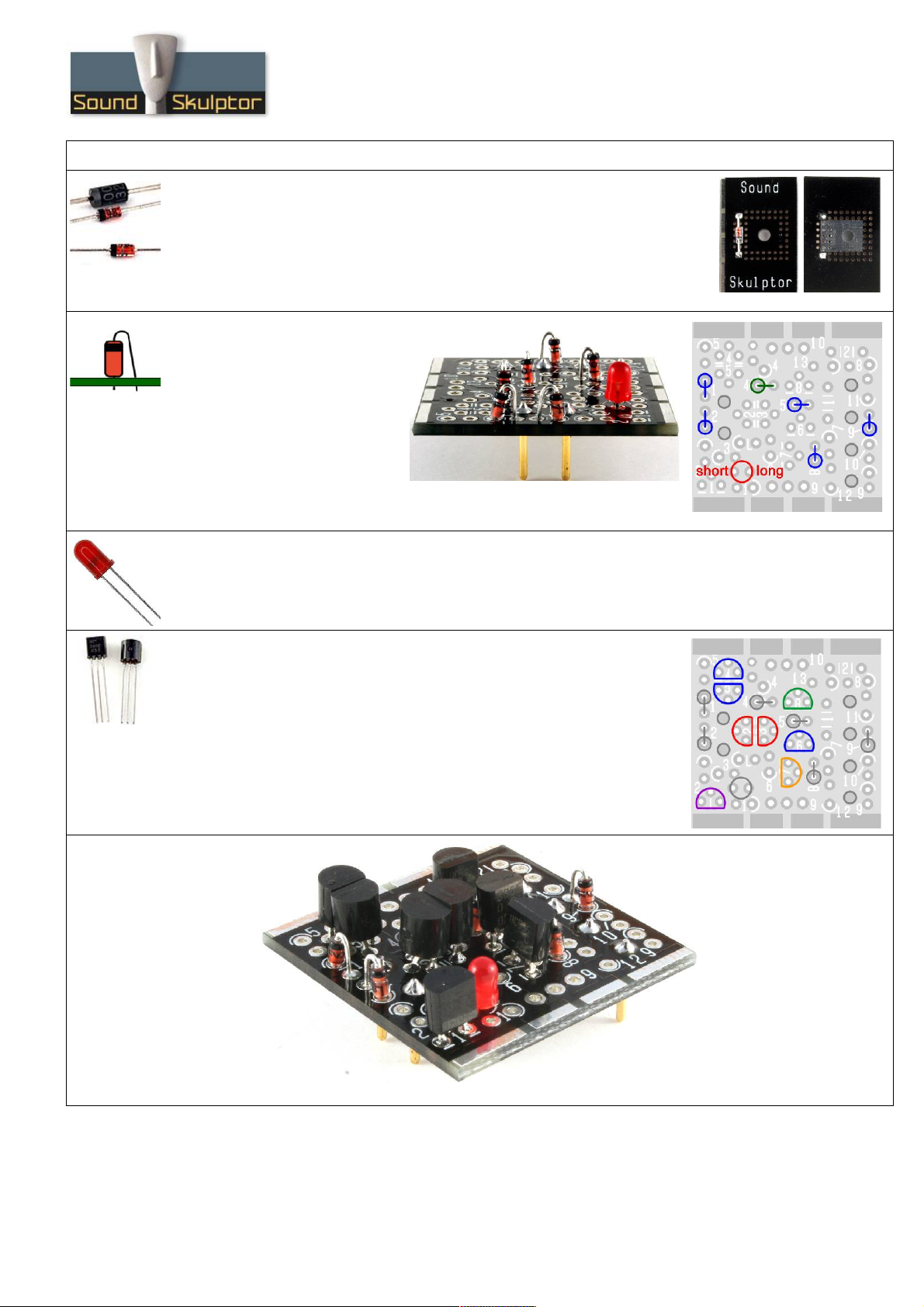
4. Diodes D5 & D6
Add D5 and D6 on the 2 heatsink PCB's.
When soldering, be careful not putting any solder on the power transistor
plane.
Warning: Make sure to respect the direction of the diodes which is marked by
a ring on the component and a double line on the PCB marking.
5. Other diodes
These diodes are mounted
vertically, cathode (black ring) up.
Add D1, D2, D7, D8, D :
1N4148, blue on the picture.
Add D4: zener 5.1V, green on
the picture.
Warning : Make sure to respect the direction of the diodes. D7, D8, D
are mis-labeled on the PCB, follow the layout document.
6. LED
Add the red LED D3, red on the picture.
Warning : Make sure to respect the long lead/short lead direction of the diode.
7. Transistors
Add Q1: BC560C (purple)
Add Q2, Q3: KSA 2 (red)
Add Q4, Q5, Q6: BC550C (blue)
Add Q7: BC556C (orange)
Add Q8: BC546C (green)
Press firmly the transistors against the PCB in order to keep the profile
low.
Copyright ©2014 to Today SoundSkulptor

www.soundskulptor.com
Document revision 1.1 – Last modification : 10/08/17
SK Assembly guide
8. Inductor
Add L1 (red).
Bend sharply one of the leads against the body of L1 for a vertical
insertion.
. Resistors
Bend sharply one of the leads against the body the resistor for a vertical
insertion.
Add R1 to R13.
Warning : It is very important to check the resistors value with a DMM
because the colour code can be ambiguous. For example 1K (brown-black-
black-brown-brown) can be confused with 110R (brown-brown-black-black-
brown).
10. Capacitors
Add C1 and C2.
11. Q & Q10 assembly
Attach Q (BD13 ) to the heatsink PCB marked “Sound Skulptor” with
a M3x12 mm screw and a M3x20 mm spacer. The transistor is placed
on the side with no writing.
Tighten softly, by hand for now.
Copyright ©2014 to Today SoundSkulptor
www.soundskulptor.com
Document revision 1.1 – Last modification : 10/08/17
SK Assembly guide
12. Q & Q10 assembly
Similarly, attach Q10 (BD140) to the heatsink PCB marked “SK ” with a
M3x12 mm screw and screw it into the other side of the spacer. The transistor
is placed on the side with no writing.
Tighten softly, by hand for now.
13. Q & Q10 assembly
Insert the 2 power transistor leads into the main PCB. The word “Sound” is
on the input side (2 golden pins). The word “Skulptor” is on the output side
(4 golden pins).
Turn upside down, press on a flat table, adjust the position, making sure that
the heatsinks are parallel to the main PCB edge then solder the transistor
pins. Cut the leads sharp.
Keeping the DOA pressed against the table, tighten the 2 screws with a
screwdriver.
14. Q & Q10 assembly
Solder the 4 pads at the bottom of both heatsinks
that connect to the main PCB. These solders improve
the mechanical stiffness of the DOA and make the
electrical connection of diodes D5 & D6.
15. R1
Pull R1 back a little in order to avoid its top touching the solder joint of D5. In several cases we
have seen failures caused by such a contact in spite of the paint covering the resistor body.
16. D5 & D6 thermal contact
Press the body of D5 and D6 against the heatsink and put a drop of instant glue between the two. This
will create a permanent thermal contact.
17. Congratulations!
Your SK is ready for test.
Copyright ©2014 to Today SoundSkulptor
Table of contents
Other Sound Skulptor Stereo System manuals


