Sound Skulptor Switcher-2 User manual
www.soundskulptor.com
Document revision 1.3 – Last modification : 09/10/14
Switc er-2 Assembly guide
Safety warning
T e kits are main powered and use potentially let al voltages. Under no circumstance s ould someone undertake t e
realisation of a kit unless e as full knowledge about safely andling main powered devices.
Please read t e “DIY guide” before beginning.
Print or open t e following documents :
• Switc er-2 Sc ematics
• Switc er-2 Components layout
• Switc er-2 Parts list
Follow t is guide from item number 1 till t e end, in t is order. T e assembly order is based on components eig t, from
low to ig profile, in order to ease t e soldering process : T e component you are soldering is always taller t an t e
previously assembled ones and it is pressing nicely against t e work area foam.
Switc er-2 Assembly guide – Main PCB
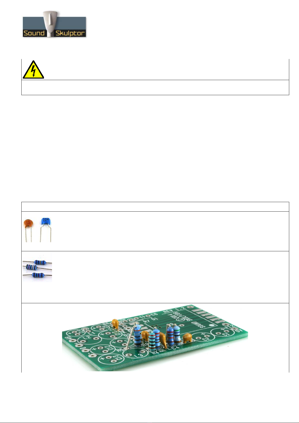
1. Ceramic capacitors
Add C4, C5, C7, C8.
C3 w ic is placed
under
t e PCB will be installed later.
2. Resistors
Add R1 to R5 and R8. R7 will be installed later in order to leave an easy access for soldering t e
transformer.
T e resistors are installed vertically.
Warning : It is very important to c eck t e resistors value wit a DMM because t e colour code can be
ambiguous. For example 1K (brown-black-black-brown-brown) can be confused wit 110R (brown-brewn-
black-black-brown).
Copyrig t ©2013 to Today SoundSkulptor
www.soundskulptor.com
Document revision 1.3 – Last modification : 09/10/14
Switc er-2 Assembly guide – Main PCB
3. Ceramic capacitor C3
Add C3
under
t e PCB.
Cut t e leads ultra s ort.
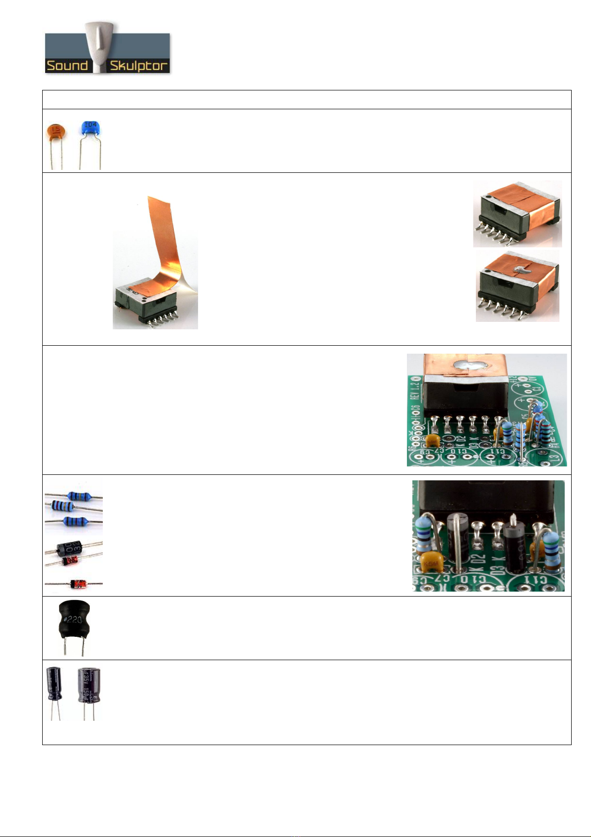
4. Copper s orted turn
In order to reduce t e transformer radiations we will add a
copper foil turn around t e outside of t e transformer.
Start by redrawing t e dot on t e top of t e transformer, a
little furt er in t e corner because t e original will be idden
by t e foil.
Partially remove t e backing tape from t e ad esive copper
foil and place it on t e top of t e transformer, as s own on
t e picture. Make a full w ile removing t e backing tape.
Solder t e two ends to electrically close t e loop.
5. Transformer soldering
Apply a small quantity of solder on one of t e transformer PCB
pads.
Position t e transformer, making sure t e dot is in t e correct
place and reflow t e pad solder to lock t e transformer. Adjust
until all t e transformer pins are all well centred on t eir respective
pad. Solder one pin on t e opposite row. W en t e position is
correct, solder all t e pins.
6. Resistor R7 & diodes D2, D3
Add R7 and diodes D2, D3.
T e R7 silk-screen writing is idden by t e transformer. It is
adjacent to C7 and D2.
T e diodes are also placed vertically, cat ode on top. Bend t e
cat ode lead (marked by a ring on t e diode body).
Warning : Make sure to respect t e direction of t e diodes. T e
cat ode side is marked by a K on t e PCB.
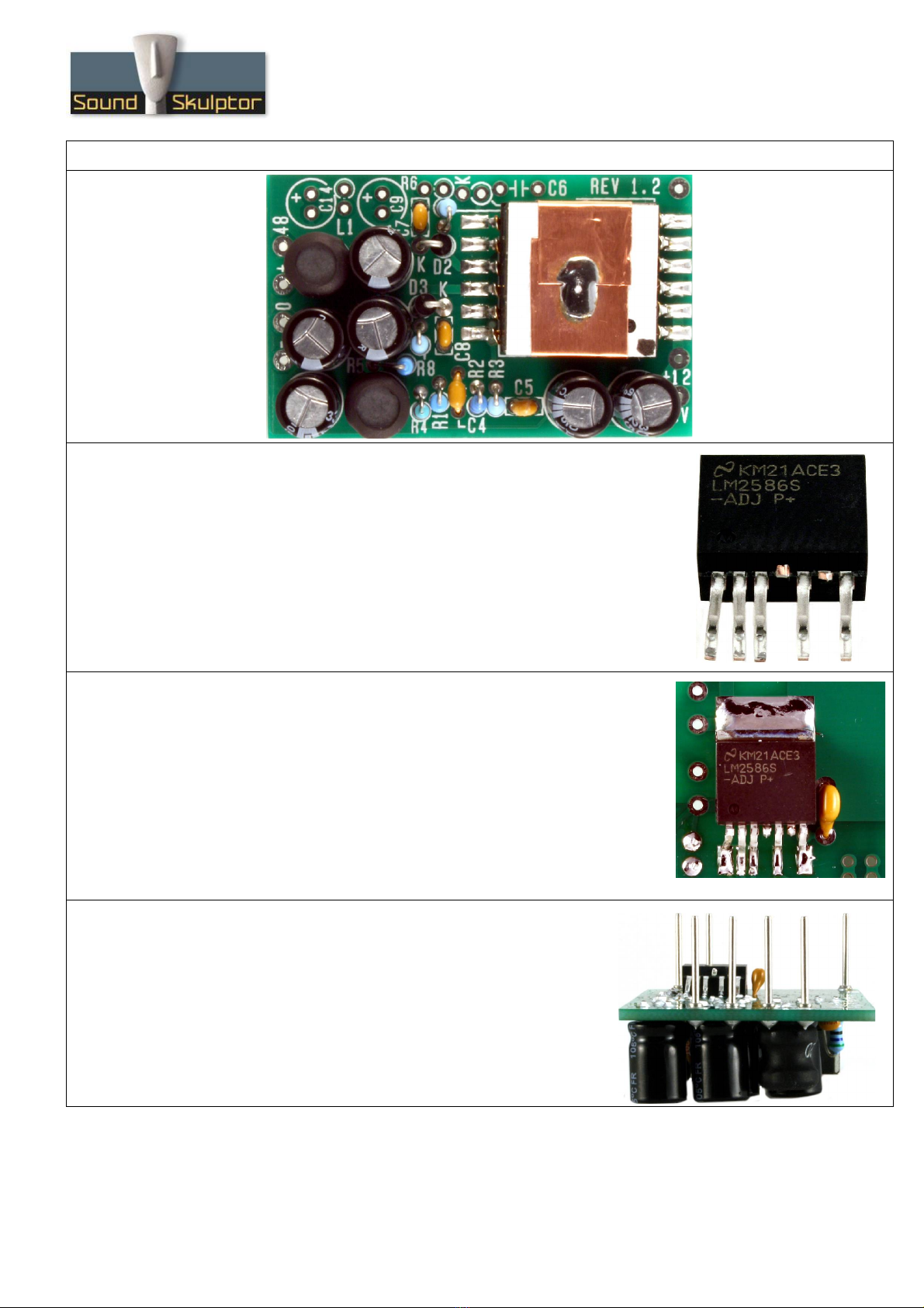
7. Radial inductors
Add L2, L3.
8. Electrolytic capacitors
Add C1, C2, C10 to C13.
Solder one lead first, adjust verticality t en solder t e second lead.
Warning : T e +lead must go into t e + ole. Do not reverse (t ey may explode !)
Warning : Make sure t e caps are inserted as low as possible because t ey define t e eig t of t e
module.
Copyrig t ©2013 to Today SoundSkulptor
www.soundskulptor.com
Document revision 1.3 – Last modification : 09/10/14
Switc er-2 Assembly guide – Main PCB
9. LM2586
T e LM2586 is soldered on t e back side of t e PCB.
It is a surface mount component wit relatively close pins. In order to make
t e soldering process easier, we are going to c eat a little:
Lift pins 4 and 6 (counting from t e left) and cut t em off.
And gently bend pin 1 towards t e left.
T is gives us a good iron access to eac pin.
10. Soldering t e LM2586
Put a small quantity of solder on t e rig tmost pad. Place t e IC and
reflow t e solder, adjusting t e position until all t e pins are centred on
t eir respective pad.
Once in position, solder t e ot er pins.
Do not forget t at a bad solder joint is almost always caused by too
muc solder.
Last t ing is to solder t e IC top tab to t e PCB. Start by eating t e
metal tab until t e solder flows and goes down to t e PCB.
11. Connecting pins
Insert t e 7 long pins from t e solder side and solder. It is
necessary to put a little pressure on t e pins to insert t em all
t e way down.
Copyrig t ©2013 to Today SoundSkulptor

www.soundskulptor.com
Document revision 1.3 – Last modification : 09/10/14
Switc er-2 Assembly guide – Main PCB
12. Spacer
Stick t e rubber spacer on t e Switc er3 PCB,
at t e position s own on t e picture, between
t e solder pads.
Switc er-2 Quick testing
T e switc er can be tested directly in t e SK501 module but it is a good idea to c eck it alone if you can. W at you
need is a 12V DC source and a voltmeter.
Connect t e 12V source between t e (+12)
and (0V) supply pins (near transformer) and
connect t e voltmeter between t e (0) and
(+) pins on t e output side.
After powering, you s ould read
+19 to 20Volts on t e (+) pin,
-19 to -20Volts on t e (-) pin,
T e full test requires pulling current and will be
done in t e MC624.
Switc er-2 Assembly guide – S ield
1. PCB split
Split t e s ield PCB into 6 pieces.
2. PCB split
Break t e 2 sides along t e ole line and smoot out t e jagged side by rubbing it on
a piece of sand paper.
Copyrig t ©2013 to Today SoundSkulptor

www.soundskulptor.com
Document revision 1.3 – Last modification : 09/10/14
Switc er-2 Assembly guide – S ield
3. Soldering side A
Use a tool wit a s arp rig t angle, like a ruler or an aluminium profile to elp
position t e sides. Place t e top side flat on t e table (“Sound Skulptor”
facing down) and t e (A) labelled side at a 90° angle. (A) edge against (A)
edge. T e vertical panel rests on t e table, not on t e top panel. Solder t e
centre pad. Reflow t e solder until t e 2 panels are perfectly lined and at 90°
t en solder t e next 2 pads.
4. Soldering side B
Repeat t e same operation for side B
5. Soldering sides C and D
Position t e C side against t e assembly and
solder t e centre pad.
Next solder t e 2 low corners. Do not solder t e
top angles yet.
Repeat for t e D side.
Copyrig t ©2013 to Today SoundSkulptor

www.soundskulptor.com
Document revision 1.3 – Last modification : 09/10/14
Switc er-2 Assembly guide – S ield
6. Switc er-S ield assembly
Warning: T is must be done after t e switc er as been fully tested in t e
MC624.
Insert t e switc er PCB into t e s ield, making sure t e pins position
follows t e s ield top writing.
C eck t at t e PCB is orizontal and solder t e connecting pad on t e
side.
7. Closing t e s ield
Place t e closing side over t e switc er PCB. C eck t at it is
orizontal and regularly recessed t en solder t e pads.
Copyrig t ©2013 to Today SoundSkulptor
Table of contents
Other Sound Skulptor Stereo System manuals


