Sound Tube WLL-TR-1p-II Configuration guide
© 2020 MSE Audio. All rights reserved. PN INS-WLL-TR-1p-II Rev 02.04.2020
1.855.663.5600 | mseaudio.com | soundtube.com
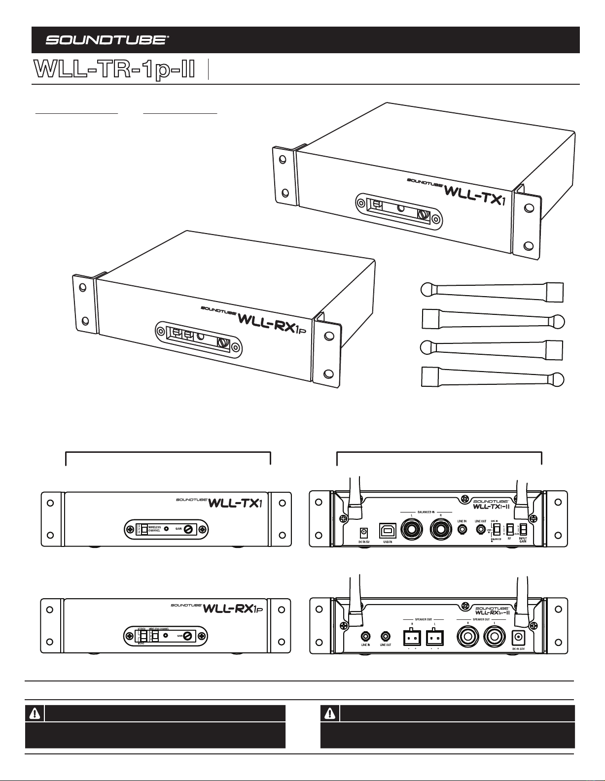
Front Rear
Transmitter BoxContents
1- WLL-TX1wirelesstransmitter
1- Powersupply
Output:5VDC1.2A
2- Halfrackmountadapters
2- Antenna
TXunit-Transmitter TXunit-Transmitter
RXunit- Receiver/Amp RXunit- Receiver/Amp
TXunit-Transmitter
RXunit- Receiver/Amp
Antenna (4)
Receiver BoxContents
1- WLL-RX1pwirelessreceiver/ampunit
1- Powersupply
Output:32VDC3.75A
2- Halfrackmountadapters
2- Antenna
2-Two-pinEuro-blockconnectors
FCC ID: XCO-HSWLLT IC:7756A-HSWLLT
Avis
Les produits SoundTube doit être installé par un installateur professionnel audio/contractuer.
Pour plus de sûreté et pour des performances audio optimales, l'installateur doit suivre toutes
les instructions émises par SoundTube.
Warning
SoundTube products must be installed by a professional audio installer/contractor. For safety
and for optimum audio performance, installer must follow all directions issued by SoundTube.
-II
-II
-II
-II
WLL-TR-1p-II
Install Instructions For:
WLL-TR-1p-II (WLL-TX1-II transmitter and WLL-RX1p-II receiver/amp).
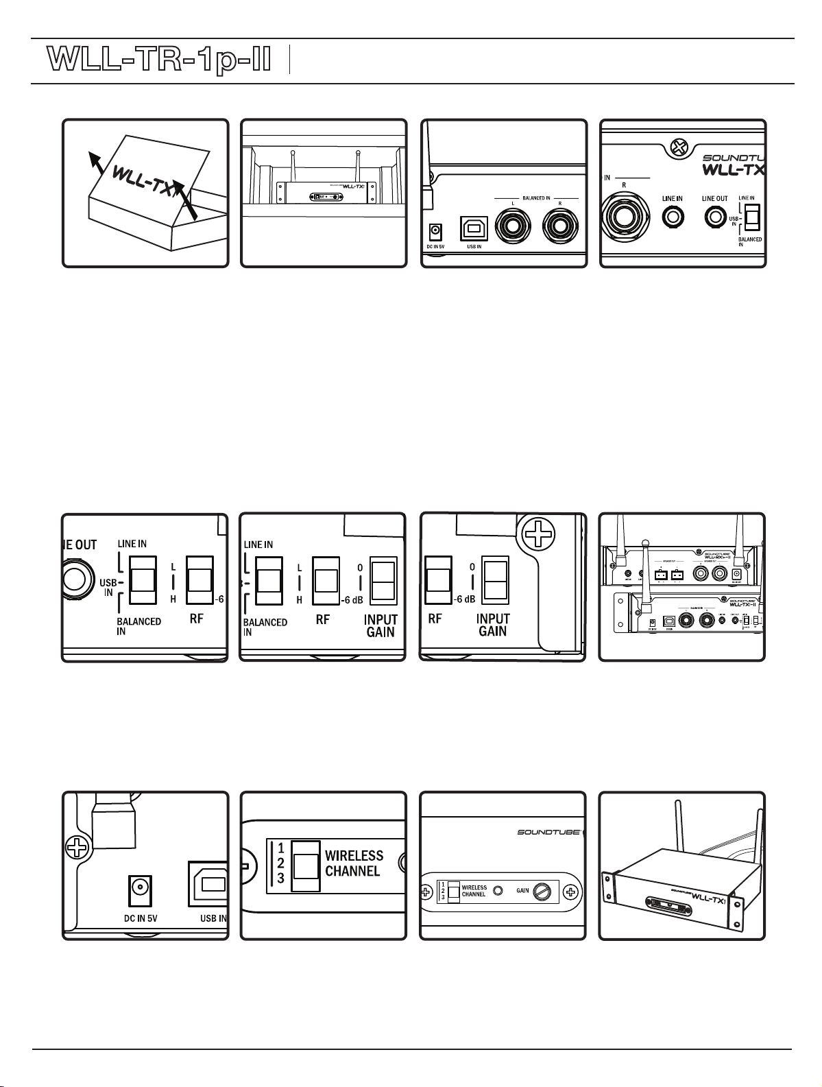
1. Remove unit from box.
8. For bestresults,Transmitterand
Receiverantennas should face the
samedirection(either vertically or
horizontally).
7. Set INPUT sensitivity switch at
0 dB for normal use. If using a
high output source, set the switch
to -6dB.
6. Set RF power switch. Two
options are available, High (H) and
Low (L). The High setting is
recommended for maximum
distance. The low setting is for
installations where 2 or more
TX-1’s are on the same channel
within 60-70 ft of each other.
5. Set input switch to match the
desired input source.
2. Determine location for
placement of WLL-TX1-II. The
WLL-TX1-II may be installed in an
equipment rack (half rack adapter
required) or on a shelf.
-II
4. If desired, the variable LINE
OUT mini jack can be connected
to an external device such as an
ADA hearing assistance system.
3. Connect desired input source to
rear panel. You may use balanced
(1/4” TRS) connectors, unbalanced
mini or USB. Multiple sources may
be connected but only the source
selected on the input switch (step
5) will be sent to the transmitter.
When connecting through the USB
input do not connect an input to
the balanced or line in.
11. After installation of
WLL-RX1p-II unit(s), apply power
to WLL-TX1-II. Adjust front panel
gain knob as needed. The gain
control will adjust the level of both
the input audio and the LINE OUT
feed.
10. On front panel, select transmit
channel 1, 2 or 3. NOTE: the
WLL-RX1p-II unit(s) must be set on
the same channel.
9. Connect power supply to DC IN
5V connector.
12. Done!
(The LED on the front panel will
be red when power is applied to
the TX unit. It will turn blue when
the TX unit is in communication
with the RX).
WLL-TX1-II Install Instructions
-II
Installation Notes: 2a: an installation that puts the WLL-TX1-II in line-of-sight with the WLL-RX1P-II will provide the best results. 2b: Do not install transmitter
more than 230 feet (70 meters line of site or 50 meters indoors) from the desired receiver location(s). 3a: If using the USB input, the WLL-TX1-II will appear as
an audio device on your computer’s control panel.
WLL-TR-1p-II
Install Instructions For:
WLL-TR-1p-II (WLL-TX1-II transmitter and WLL-RX1p-II receiver/amp).
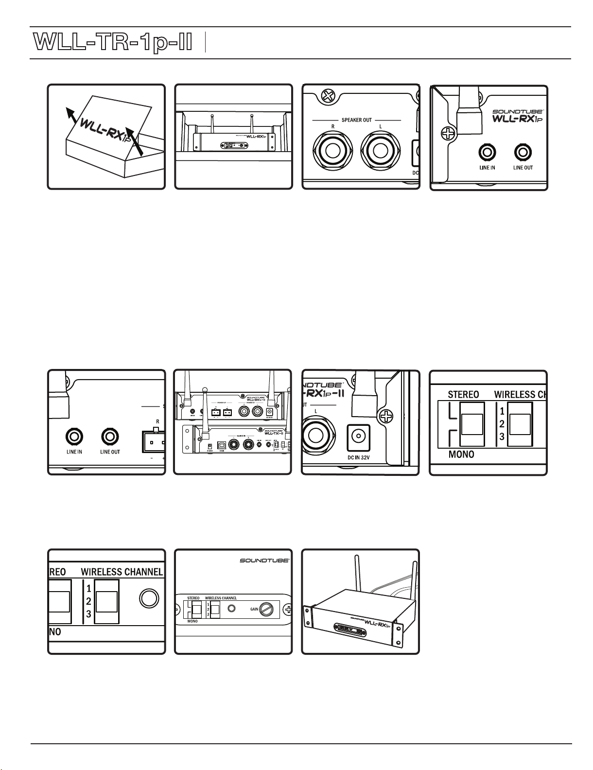
1. Remove unit from box.
8. Selecteither the Stereo or Mono
operationmode via the selector
switchon the front panel.
7. Connect the power supply to
the DC IN 32V power connector.
6. For best results, Transmitter
and Receiver antennas should
face the same direction (either
vertically or horizontally).
5. If desired, a xed LINE OUT audio
signal is provided by the stereo mini
jack for operating a device such as an
ADA hearing assistance system.
2. Determine location for
placement of WLL-RX1p-II. The
WLL-RX1p-II may be installed in
an equipment rack (half rack
adapter required) or on a shelf.
The antennas may be remoted
using a wi antenna cable (not
included; available through third
party vendors).
4. If desired, a direct audio source
can be connected to the
WLL-RX1p-II via the mini “LINE IN”
jack. Note: If an audio source is
connected to this input, it will
interrupt any RF feed being sent
via the WLL-TX1-II.
3. Connect 4 ohm or 8 ohm
speakers to the L and R channel
output leads using the Euroblock
connectors and push into place in
the appropriate SPEAKER OUT
locations. Alternatively, speakers
may be connected via ¼” plugs at
the L and R “SPEAKER OUT” jacks
to the right of the Euroblock
connectors. Do not connect both.
Be certain to check for the correct
connection polarity.
11. Done!
10. Apply power to unit. Adjust front
panel gain control as needed.
9. Select the receiving channel 1, 2
or 3 on the front panel. NOTE: the
WLL-TX1-II must be set on the
same channel.
Note: If the signal appearing at the receiver is intermittent or noisy, (a) make sure the transmitter’s RF Gain switch is on High; (b) change the location of the
transmitter and/or receiver for line-of-sight position with one another; (c) place the antennas in a line-of-sight position using an antenna extension cable
(available from third party vendors).
WLL-RX1p-II Install Instructions
-II
Installation Notes: 2a: an installation that puts the WLL-TX1-II in line-of-sight with the WLL-RX1p-II will provide the best results. 2b: Do not install transmitter
more than 230 feet (70 meters line of site or 50 meters indoors) from the desired receiver location(s). 3a: Unit output is 50 watts per channel.
WLL-TR-1p-II
Install Instructions For:
WLL-TR-1p-II (WLL-TX1-II transmitter and WLL-RX1p-II receiver/amp).

WLL-TR-1p-II
Install Instructions For:
Transmitter Interference: If the WLL-TX1-II causes interference with other wireless devices in the area, try the following: (a) select a different
channel setting on both the transmitter and receiver (step 10); (b) change RF Gain switch to Low setting (step 7); (c) alter antenna positions on
both transmitter and receiver (antenna positions should match each other).
If using two WLL-TX1-II units separate them by at least 2 ft. If using 3, separate them by at least 5 ft. When using more then 3 transmitters,
the RF switch should be set to low if the systems are within 60-70 ft. of each other. If they have problems establishing a link with the
WLL-RX1p-II move the WLL-TX1-II’s further apart. The transmitting signals can interfere with each other if they are too close together.
FCC Notice
This device complies with Part 15 of the FCC Rules. Operation is subject to the following two conditions: (1) this device may not cause
harmful interference, and (2) this device must accept any interference received, including interference that may cause undesired operation.
Le présent appareil est conforme aux CNR d'Industrie Canada applicables aux appareils radio exempts de licence. L'exploitation est
autorisée aux deux conditions suivantes : (1) l'appareil ne doit pas produire de brouillage, et (2) l'utilisateur de l'appareil doit accepter tout
brouillage radioélectrique subi, même si le brouillage est susceptible d'en compromettre le fonctionnement.
Changes or modications not expressly approved by the party responsible for compliance could void the user's authority to operate the
equipment.
This equipment has been tested and found to comply with the limits for a Class B digital device, pursuant to part 15 of the FCC Rules. These
limits are designed to provide reasonable protection against harmful interference in a residential installation. This equipment generates uses
and can radiate radio frequency energy and, if not installed and used in accordance with the instructions, may cause harmful interference to
radio communications. However, there is no guarantee that interference will not occur in a particular installation. If this equipment does cause
harmful interference to radio or television reception, which can be determined by turning the equipment off and on, the user is encouraged to
try to correct the interference by one or more of the following measures:
(1) Reorient or relocate the receiving antenna. (2) Increase the separation between the equipment and receiver. (3) Connect the equipment
into an outlet on a circuit different from that to which the receiver is connected. (4) Consult the dealer or an experienced radio/TV technician
for help.
Under Industry Canada regulations, this radio transmitter may only operate using an antenna of a type and maximum (or lesser) gain
approved for the transmitter by Industry Canada. To reduce potential radio interference to other users, the antenna type and its gain should
be so chosen that the equivalent isotropically radiated power (e.i.r.p.) is not more than that necessary for successful communication.
Conformément à la réglementation d'Industrie Canada, le présent émetteur radio peut fonctionner avec une antenne d'un type et d'un gain
maximal (ou inférieur) approuvé pour l'émetteur par Industrie Canada. Dans le but de réduire les risques de brouillage radioélectrique à
l'intention des autres utilisateurs, il faut choisir le type d'antenne et son gain de sorte que la puissance isotrope rayonnée équivalente (p.i.r.e.)
ne dépasse pas l'intensité nécessaire à l'établissement d'une communication satisfaisante.
MPE Notice
To satisfy FCC RF exposure requirements, a separation distance of 20 cm or more should be maintained between the antenna of this device
and persons during device operation. To ensure compliance, operations at closer than this distance are not recommended.
Les antennes installées doivent être situées de facon à ce que la population ne puisse y être exposée à une distance de moin de 20 cm.
Installer les antennes de facon à ce que le personnel ne puisse approcher à 20 cm ou moins de la position centrale de l’ antenne. La FCC
des États-Unis stipule que cet appareil doit être en tout temps éloigné d’au moins 20 cm des personnes pendant son functionnement.
IC Notice
This device complies with Industry Canada licence-exempt RSS standard(s). Operation is subject to the following two conditions: (1) this
device may not cause interference, and (2) this device must accept any interference, including interference that may cause undesired
operation of the device.
Le présent appareil est conforme aux CNR d'Industrie Canada applicables aux appareils radio exempts de licence. L'exploitation est
autorisée aux deux conditions suivantes : (1) l'appareil ne doit pas produire de brouillage, et (2) l'utilisateur de l'appareil doit accepter tout
brouillage radioélectrique subi, même si le brouillage est susceptible d'en compromettre le fonctionnement.
Only for detachable antennas: This radio transmitter (identify the device by certication number, or model number if Category II) has been
approved by Industry Canada to operate with the antenna types listed below with the maximum permissible gain and required antenna
impedance for each antenna type indicated. Antenna types not included in this list, having a gain greater than the maximum gain indicated for
that type, are strictly prohibited for use with this device.
Le présent émetteur radio (identier le dispositif par son numéro de certication ou son numéro de modèle s'il fait partie du matériel de
catégorie I) a été approuvé par Industrie Canada pour fonctionner avec les types d'antenne énumérés ci-dessous et ayant un gain admissible
maximal et l'impédance requise pour chaque type d'antenne. Les types d'antenne non inclus dans cette liste, ou dont le gain est supérieur
au gain maximal indiqué, sont strictement interdits pour l'exploitation de l'émetteur.
Gain d'antenne: 2.0dBi maximal
Type d'antenne: 50 Ω BNC, monopole antenne
For Module only:
Information for the OEMs and Integrators- This device is intended for OEM integrators only. Please see the full Grant of Equipment document
for restrictions. This device must be operated and used with a locally approved access point.
Label Information to the End User by the OEM or Integrator- If the FCC ID of this module is not visible when it is installed inside another
device, the the outside of the dvice into which the module is installed must be labeled with “Contains FCC ID: SU3RM2400A” in a visible area.
WLL-TR-1p-II (WLL-TX1-II transmitter and WLL-RX1p-II receiver/amp).
This manual suits for next models
2
Other Sound Tube Receiver manuals


