SoundArt Chromasonic User manual

USER’S MANUAL
revision 2 | 11.2003
soundskin version 1.11
www.soundart-hot.com

ii
Copyright © 2001-2003 Soundart
www.soundart-hot.com
Soundart makes no warranty of any kind, expressed or implied, with respect to the contents or use
of the material in this document or in the software and hardware it describes, and specifically
disclaims any responsibility for any damages derived from its use. Hardware and Software may
contain design defects or errors known as errata, which may cause the product to deviate from
published specifications. Soundart reserves the right to revise and modify the topics covered in this
book periodically, which are subject to change without notice. This document may be reproduced
and distributed freely, provided no alterations of any kind are made. Soundart software is subject to
the terms of the Soundart Tools Software license. Third party software is subject to the terms of their
respective owners license. Third party trademarks and registered trademarks are property of their
respective owners.

Chromasonic User’s Manual
iii
Table of Contents
1
11
1Overview
OverviewOverview
Overview ................................
................................................................
................................................................
................................................................
................................................................
................................................................
.........................................
..................
.........4
44
4
1.1 Main features.........................................................................................4
1.2 Sound Architecture................................................................................6
1.3 Getting Started ......................................................................................8
1.3.1 Making the connections ...........................................................8
1.3.2 Loading the soundskin..............................................................8
2
22
2Operating Modes
Operating ModesOperating Modes
Operating Modes................................
................................................................
................................................................
................................................................
...........................................................
......................................................
...........................10
1010
10
2.1 Preset Mode........................................................................................ 12
2.1.1 The Main Display.................................................................... 12
2.1.2 Working in Preset Mode........................................................ 14
2.1.3 Changing to other modes...................................................... 14
2.2 Edit Mode............................................................................................ 16
2.2.1 Working in Edit Mode ............................................................ 16
2.2.2 Activating/Deactivating an Effect Slot ................................. 30
2.2.3 The Real-Time Controllers ..................................................... 31
2.2.4 Potentiometer Groups ........................................................... 32
2.2.5 Comparing your Edits with the stored Preset ...................... 33
2.2.6 Finishing and Preparing to Save Edits .................................. 33
2.2.7 Naming and Numbering........................................................ 34
2.3 System Mode...................................................................................... 36
2.4 Assign Info Mode................................................................................ 39
A
AA
ALoading Soundskins
Loading SoundskinsLoading Soundskins
Loading Soundskins................................
................................................................
................................................................
................................................................
.......................................................
..............................................
.......................40
4040
40
B
BB
BMidi Implementation
Midi ImplementationMidi Implementation
Midi Implementation ................................
................................................................
................................................................
................................................................
....................................................
........................................
....................42
4242
42

4
Overview
1 Overview
Chromasonic
is a soundskin that turns your Soundart Chameleon multi-
purpose DSP hardware into a professional audio multi-effects processor. Once
Chromasonic is loaded by MIDI, the Chameleon behaves in exactly the same
way as any other multi-effects unit.
1.1 Main features
You can run up to three stereo effects at any one time, and chain them
together in a wide variety of ways. You can choose from:
Two Tap Delay
5 Band Parametric Equalizer
Compressor
Limiter
Noise Gate
Tremolo
Chorus
Flanger
Phaser
Reverb (here you are restricted to only one instance at any time
because it is the most sophisticated and DSP hungry of the effects)
Autopanner
WahWah
4-voice Pitch Shifter
1
Cha
p
ter

Chromasonic User’s Manual
5
You will also find the following features:
Extensive signal routing capabilities
Flexible system parameters configuration
Tempo Sync (internal, external and tap) for the time based effects
128 user presets to store effect combinations permanently
Factory bank with 64 presets included
Compare preset function for checking what the stored preset
sounds like in comparison to the one you have arrived at while
editing
Comprehensive MIDI implementation allowing you to modify
parameters using external MIDI controllers, record parameter
changes using a sequencer, and make/receive SYSEX dumps that
store your own presets and configurations
You can assign any of the Chameleon front panel Realtime
controller pots to control virtually any internal parameter for hands
on control and performance duties
You can assign the standard MIDI Expression Controller (number
11) to virtually any effect parameter
Signal meters - Input, Output and Gain Reduction (gain reduction
meters only show when you are using the relevant effects - a
Compressor, a Limiter, or a Gate - in one of the three FX Slots)

6
1.2 Sound Architecture
BASIC DESCRIPTION
BASIC DESCRIPTIONBASIC DESCRIPTION
BASIC DESCRIPTION
Chromasonic
ChromasonicChromasonic
Chromasonic can really be considered to consist of three separate effect units
that are linked together in order into a string of processors (FX1, FX2 and
FX3). They each receive mono signal inputs and generate stereo signal
outputs once they have done their thing. The exact configuration of these
three FX Slots is quite flexible and allows for a wide variety of routing
options, and you can mix the effects back with the original unprocessed
sound along the way.
As you work along the chain from FX1 > FX2 > FX3, you have more and more
input options for each FX Slot.
THE ROUTING WORKS LIKE THIS
THE ROUTING WORKS LIKE THISTHE ROUTING WORKS LIKE THIS
THE ROUTING WORKS LIKE THIS
At the start of this chain, the mono input for FX1 can only be selected from
the Chameleon physical audio inputs - either L, R or L+R (which means the
Left and Right signals are summed together). You can control the volume of
this input.
FX2 and FX 3 can receive their input in the same way. But they can also be
set to receive signals from the output of any preceding FX Slot in the chain
instead. That is to say, FX2 can also be set to receive processed signals from
FX1, while FX 3 can also receive processed signals from FX1 or from FX2.
Once each FX Slot has ‘done its thing’ you can mix the processed signal back
in with the input signal it receives, by adjusting the slots own ‘Dry/Wet mix’.
From here this stereo processed and mixed signal can then be sent on
towards the output.
MIXING FOR THE OUTPUT
MIXING FOR THE OUTPUTMIXING FOR THE OUTPUT
MIXING FOR THE OUTPUT
By adjusting the final Left and Right output levels that come from each FX
Slot you can balance the three signals together on their way to the main
output, both in terms of volume and stereo position.
But before the sounds leave the Chameleon, you have one last mixing
option. If you think again for a moment of the mix of the three FX Slots as
one whole processed signal, you can mix this back in with the original signal
(the ‘Dry Source’). This is the ‘Global Dry/Wet mix’.
EXAMPLES AND DIAGRAMS
EXAMPLES AND DIAGRAMSEXAMPLES AND DIAGRAMS
EXAMPLES AND DIAGRAMS
So as you can imagine it is possible to configure Chromasonic to run three
different FX side by side, each taking the input signal, processing it and
sending it to the output. Or you might configure it so that each FX Slot
receives its signals directly from the previous one, adding more and more
Chromasonic User’s Manual
7
layers of effects as it passes through the three FX Slots until FX3 sends it to
the output. (This would be achieved by turning down to zero the output
signals of FX1 and FX2 that are sent to the main output mix, but setting the
inputs of FX2 and FX3 to ‘listen’ to the previous effect in the chain).
You could even configure it so that Chromasonic runs two mono effects
totally independently - one type of effect over the left input signal and
another over the right signal. This is because you have separate control over
the left and right outputs for each FX Slot.
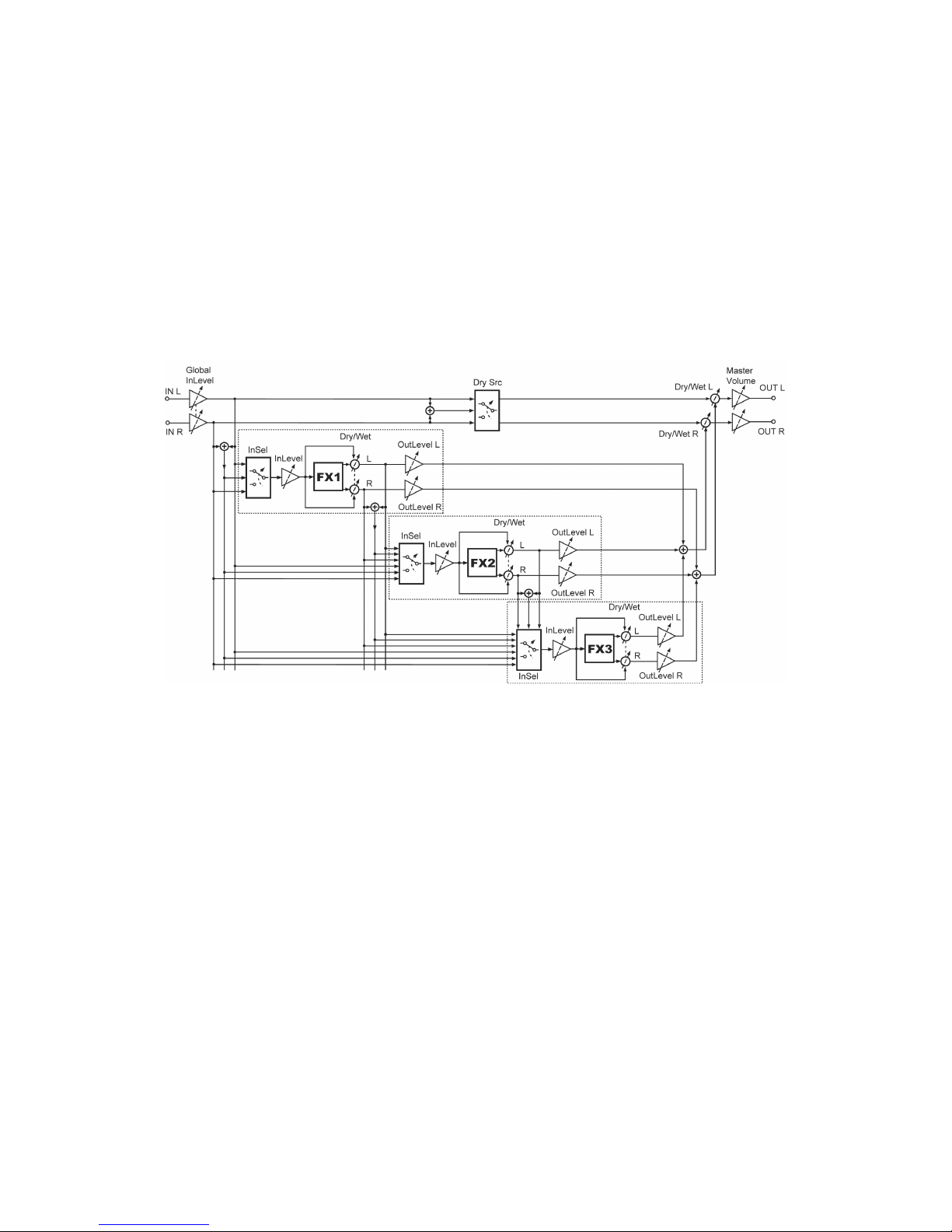
There is, of course, a whole world of mixing subtleties in between. The next
figure shows a block diagram of the audio signal path inside Chromasonic as
described above.
You can see that the three FX Slots are essentially identical, except that FX2
and FX3 have more and more input options.
On the right of the FX Slots you can see first the three signals being mixed
together, and then this mix being balanced with the original Dry Source by
the Global Dry/Wet mix just before the main output.
The very last thing in the chain, the Master Volume, is controlled directly
from the Volume knob on the front panel of the Chameleon, as you might
expect.

8
1.3 Getting Started
This section explains how to get started with Chromasonic for the first time.
1.3.1
1.3.11.3.1
1.3.1
Making the connections
Making the connectionsMaking the connections
Making the connections
In order to start using Chromasonic, you need first to have the Chameleon
unit properly connected if you haven’t already done so. Make sure that you
have the Chameleon power supply (9V DC/1.2A) plugged to the device and
connected to the AC mains. The following figure shows the Chameleon rear
panel connections.
Before connecting the Chameleon to other units in your system, for safety
ensure that the power to all units is off.
There are no real surprises here: to get sounds into Chromasonic connect
your sound source outputs (amplifier, mixer aux bus sends, etc.) to the
Chameleon audio inputs. To hear the results, now connect audio cables from
the left and right Chameleon outputs to a suitable amplifier or mixing desk
(line level inputs), or use your headphones using the front panel jack.
You also need to connect your MIDI sequencer to the Chameleon so that it
can send and receive MIDI data. The MIDI OUT of your sequencer should be
connected to the MIDI IN of the Chameleon, and the MIDI OUT of the
Chameleon should be connected to the MIDI IN of your sequencer.
Once all connections are made, turn on the power of the Chameleon and all
the other devices in your system.
1.3.2
1.3.21.3.2
1.3.2
Loading the soundskin
Loading the soundskinLoading the soundskin
Loading the soundskin
The Chromasonic soundskin is contained into a MIDI file called
‘Chromasonic_vX.X.mid’ (where ‘X.X’ is the current version number of the
soundskin). Like any other Chameleon soundskin, when you load
Chromasonic you will wipe clean the memory of the Chameleon and use it
for this new soundskin instead. So you have to first make sure you have
saved your personal settings and user data stored in the soundskin you are
about to replace with Chromasonic. You can save it by making a quick MIDI
SYSEX dump.

Chromasonic User’s Manual
9
Remember if you have an older version of Chromasonic or a different
Remember if you have an older version of Chromasonic or a differentRemember if you have an older version of Chromasonic or a different
Remember if you have an older version of Chromasonic or a different
soundskin
soundskinsoundskin
soundskin installed in your Chameleon you will lose your user data if you
installed in your Chameleon you will lose your user data if youinstalled in your Chameleon you will lose your user data if you
installed in your Chameleon you will lose your user data if you
don’t make a backup of it before updating the software version. Please read
don’t make a backup of it before updating the software version. Please readdon’t make a backup of it before updating the software version. Please read
don’t make a backup of it before updating the software version. Please read
the important notice in the Appendix A to check how to save your work and
the important notice in the Appendix A to check how to save your work andthe important notice in the Appendix A to check how to save your work and
the important notice in the Appendix A to check how to save your work and
load new soundskins into the Chameleon.
load new soundskins into the Chameleon.load new soundskins into the Chameleon.
load new soundskins into the Chameleon.
When you have loaded the latest Chromasonic, you can still reload again
your old Chromasonic presets previously backed up by MIDI. The new
software version will update the preset formatting of your presets if
necessary.
Once the soundskin is loaded, it is ready to use and you can treat the
Chameleon as if it was a regular multi-effects unit. By default, the soundskin
comes loaded with the Factory presets bank, which provide a range of ready-
to-use FX to choose from and are useful starting points for editing your own
presets. Play around with these to take a quick overview of Chromasonic.
Remember you can tweak many parameters straight away with the Realtime
controllers on the front panel.
NOTE:
NOTE:NOTE:
NOTE: Factory presets can be edited, modified and overwritten like any other
preset, so all 128 available presets are considered as “user” presets and
there are not the so called “ROM presets”. So be careful how and where you
save. However, don’t worry about overwriting the Factory presets
permanently. If you think you have made a total mess of everything the
factory bank can be reloaded at any time.
However, the factory bank reload command will reset ALL the factory
presets. So if you change one, and like it and save it, then change another,
save it, but don’t like it, if you want to return to the factory bank you will
lose both. So an idea might be that when you make an interesting preset by
adapting something from the factory bank, to always save it to an empty
slot if you have one free. That way you retain the flexibility of being able to
return to the factory bank at any time without too much pain…
Of course you could just as well overwrite the factory bank completely if you
create something better. You could even save a MIDI dump of your presets
and swap them with the other members of the Chameleon community via
the forum on our website - http://www.soundart-hot.com.

10
Operating Modes
2 Operating Modes
Chromasonic
can work in four different operating modes. These are:
Preset Mode
Preset ModePreset Mode
Preset Mode : Typical preset sound navigation, for choosing
between different FX set-ups stored in the memory.
Edit Mode
Edit ModeEdit Mode
Edit Mode : For adjusting the routing and FX parameters of a
particular preset.
System Mode
System ModeSystem Mode
System Mode : For adjusting global parameters and functions that
remain the same regardless of what preset you have loaded, e.g.
screensaver modes, MIDI SYSEX dump requests, etc.
Assign Info
Assign InfoAssign Info
Assign Info
Mode
ModeMode
Mode: This is specifically for displaying information
about the Realtime controllers (in the diagram below) - what they
are set to control and what their current value is, etc.
Each of these Modes is described in detail in their own chapter, below.
2
Cha
p
ter
Chromasonic User’s Manual
11
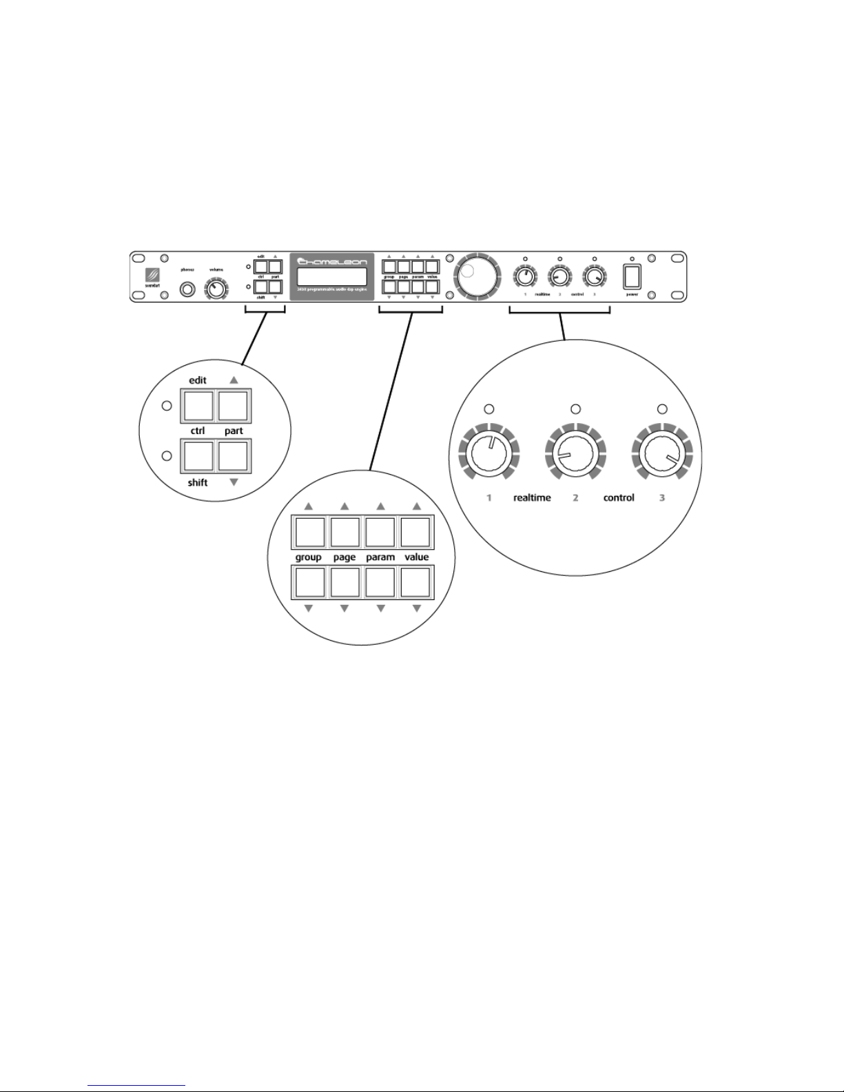
THE NAVIGATION AND CONTROL BUTTONS
THE NAVIGATION AND CONTROL BUTTONSTHE NAVIGATION AND CONTROL BUTTONS
THE NAVIGATION AND CONTROL BUTTONS
The following diagram highlights the main buttons and knobs used for
controlling Chromasonic. These are referred to throughout this manual. The
only controller not magnified here is the BIG DIAL on the left of the Realtime
controllers, in the centre.

12
Operating Modes
2.1 Preset Mode
Preset Mode is for selecting from the bank of 128 presets. A Chromasonic
preset is a combination of FX settings, routings and other such parameter
values stored in memory. When you switch on the Chameleon with
Chromasonic loaded, it automatically defaults to this Preset Mode. (the
default start-up preset number can be selected from the System Mode).
From here you can enter the other modes easily.
2.1.1
2.1.12.1.1
2.1.1
The Main Display
The Main DisplayThe Main Display
The Main Display
In Preset Mode, the LCD display will show information about the currently
loaded preset, as showed in the following picture.
Here’s a detailed list of what you see.
The upper line:
The upper line first displays the number of the currently selected
preset, which represents the memory location. This number will
blink if the preset is “dirtied” in any way - that is, the preset is
somehow changed in relation to what is stored in the memory and
it has not yet been saved. This can happen via MIDI, by moving an
assigned front panel Realtime controller, or by editing something
while in Edit Mode.
So if you change preset without first saving what you have edited,
you will lose all the changes you may have made. Equally, if you
have ended up with an effects set up you don’t like and want to
return to the saved preset, simply use VALUE UP/DOWN to change
to another a preset and back again to reload the original preset
from memory again.
You can then see the name of the selected preset beside the small
arrow in the upper line, which was assigned when the preset was
stored.
In between the name and number, the small animated arrow will
change its shape to a circular MIDI symbol whenever some MIDI
data is received through the Chameleon MIDI input.

Chromasonic User’s Manual
13
The lower line:
The lower line first shows all the active signal meters on the left.
The first meter is the stereo input signal. It shows the Input Level
after it has been attenuated by the Input Level control, a global
control you find in the System Menu. (You can also control the
global input using the Realtime controllers - see page 31).
Next to this there are the Gain Reduction meters. For each
dynamics effect loaded, there’s a small gain reduction meter,
which is displayed as a slim bar which expands downwards as gain
reduction increases. Up to three Gain Reduction meters can be
shown at a time side by side, one for each FX Slot. When no
dynamics effect is loaded into an FX Slot, its corresponding Gain
Reduction meter will remain blank.
Next is the Stereo Output signal meters, which display the stereo
output level before it goes through the Master Volume control on
the front panel. So if you turn down the Volume, the meters will
still show the output signal generated by the FX Slots.
Following the signal meters section, the name of the effect loaded
in each of the slots is displayed. Each effect is represented by its
slot number followed by a three-character abbreviation. The
different possibilities are listed below. Routing status is not
displayed here.
• OFF:
OFF:OFF:
OFF: The FX Slot is disabled
• DLY
DLYDLY
DLY: Delay
• EQ5
EQ5EQ5
EQ5: 5 band parametric EQ.
• COM
COMCOM
COM: Compressor
• LIM
LIMLIM
LIM:
Limiter
• GAT
GATGAT
GAT: Gate
• TRE
TRETRE
TRE: Tremolo
• CHO
CHOCHO
CHO: Chorus
• FLA
FLAFLA
FLA: Flanger
• PHA
PHAPHA
PHA: Phaser
• REV
REVREV
REV: Reverb
• PAN
PANPAN
PAN: Autopanner
• WAH
WAHWAH
WAH: Wah-Wah
• PIT
PITPIT
PIT: Pitch Shifter

14
Operating Modes
Finally, on the right of the lower line, the current potentiometer
group (Pot Group) number is indicated, from 1 to 4. You can
change this with the PART UP/DOWN buttons. To explain - there
are the three physical Realtime controller potentiometers (or
‘pots’) that you can assign to internal parameters, and you can
configure up to four sets of these pots, and cycle between them
controlling up to 12 parameters - hence Pot Groups.
So the Pot Group number helps you know what you are doing with
the Realtime controllers over on the right of the front panel. See
Sections 2.2.3 and 2.2.4 to know more about Realtime controllers
and Pot Groups.
SOFTWARE VERSION
SOFTWARE VERSIONSOFTWARE VERSION
SOFTWARE VERSION
In Preset Mode, by pressing the SHIFT key and holding it down you can see a
page that tells you the soundskin name and version number. As you let go of
the SHIFT key you return to Preset Mode.
2.1.2
2.1.22.1.2
2.1.2
Working in Preset Mode
Working in Preset ModeWorking in Preset Mode
Working in Preset Mode
By using the keys VALUE UP and VALUE DOWN or the BIG DIAL, you can
navigate through the bank of stored presets.
When you hold a key or move the BIG DIAL, the three character effects
abbreviations on the lower line of the display will blink indicating that you
are changing the current preset but that the new one has not been loaded
yet. When you release the key or the BIG DIAL, the word will stop blinking
indicating that the new preset has been loaded. This all takes place quite
quickly.
Note that it is possible to ‘lock’ the BIG DIAL in System Mode to avoid
accidental Preset changes in a live situation (see tables on section 2.3). You
would then only be able to change preset using VALUE UP or DOWN. (This
way you don’t worry about looking like a fool as you are tweaking the
Realtime controllers and the effect preset suddenly changes…!)
The LED lights above the Realtime controllers will be lit if they are assigned
to control anything. (Remember to note the active Pot Group).
2.1.3
2.1.32.1.3
2.1.3
Changing to other modes
Changing to other modesChanging to other modes
Changing to other modes
TO GO TO EDIT MODE
TO GO TO EDIT MODETO GO TO EDIT MODE
TO GO TO EDIT MODE
The EDIT key has two uses: when pressed and released immediately, the
operating mode will change to the Edit Mode. Here you can edit the settings
for the preset you are using. The second use is to go to System Mode…
TO GO TO SYSTEM MODE
TO GO TO SYSTEM MODETO GO TO SYSTEM MODE
TO GO TO SYSTEM MODE
If the EDIT key is pressed and held down for a moment, the operating mode
will change to System Mode. Here you can edit the global system
parameters.

Chromasonic User’s Manual
15
TO GO TO ASSIGN INFO MODE
TO GO TO ASSIGN INFO MODETO GO TO ASSIGN INFO MODE
TO GO TO ASSIGN INFO MODE
The combination of keys SHIFT+PAGE UP or SHIFT+PAGE DOWN in Preset Mode
puts the system into Assign Info Mode. Here you can see detailed info about
the status of all the Realtime controllers. To leave this mode press SHIFT. See
section 2.4 for more details on Assign Info mode.
16
Operating Modes
2.2 Edit Mode
This mode allows you to “go inside” the current preset and modify all the
parameters. As you leave Edit Mode by pressing EDIT again, you will be given
the option to save what you have been doing (see section 2.2.6 for more
information on saving your edits).
As in Preset Mode, (where the number blinks) you can easily see if the
preset has been modified from the original stored in memory. In Edit Mode
this is indicated by the LED next to the EDIT key blinking instead.
2.2.1
2.2.12.2.1
2.2.1
Working in Edit Mode
Working in Edit ModeWorking in Edit Mode
Working in Edit Mode
THE DISPLAY
THE DISPLAYTHE DISPLAY
THE DISPLAY
As well showing you the menus and parameters of the preset, the screen
also displays at all times the Input and Gain Reduction signal meters and the
Pot Group indicator. However in Edit Mode they have moved about a little
from where they were in Preset Mode:
The MIDI input activity icon has moved slightly to the left it is
shown at the very left side of the upper line.
the current Pot Group number is now shown on the right of the
upper line.
We have put the Gain Reduction meters next to this on the right
hand side of the upper line. Remember that they are active only if
you are using a dynamics effect in one of the three FX Slots.
The Stereo Input meter has not moved it is still displayed where it
was before, on the left side of the lower line. Note that the output
meter is not displayed in Edit Mode.

Chromasonic User’s Manual
17
NAVIGATION
NAVIGATIONNAVIGATION
NAVIGATION
Navigating this mode is quite easy, with parameters grouped together into
logical menus, which you can browse through to access and modify
parameters. The LCD display always tells you where you are as you navigate.
You move around with the three pairs of keys named GROUP UP/DOWN,
PAGE UP/DOWN, and PARAM UP/DOWN. You actually adjust things using the
final pair VALUE UP/DOWN and/or the BIG DIAL.
In Edit Mode, the menus have the following structure:
GROUP
GROUPGROUP
GROUP (GROUP UP and GROUP DOWN keys)
The group buttons move you between the three slots FX 1, FX 2, FX
3 and a small set of COMMON mixing parameters. The name of the
current group is shown in the upper left line of the Display.
PAGE
PAGEPAGE
PAGE (PAGE UP and PAGE DOWN keys)
For each of the Slots FX 1, FX 2 and FX 3 these keys move you
between two areas - the ‘routing’ configuration area (for choosing
how the signals flow through the FX Slot) or the effect ‘parameters’
editing area (for changing the set up of the effect itself).
In the COMMON ‘page’ these buttons do nothing as there is only
one ‘page’.
PARAMETER
PARAMETERPARAMETER
PARAMETER (PARAM UP and PARAM DOWN keys) The name of the
current parameter is shown in the lower line of the Display,
aligned to the left.
These controls will generally take you through the list of
parameters available for editing in the particular page you have
navigated to. There is only one subtle exception to this:
If you have chosen to enter the PARAMS page of an FX Slot, so that
you can set up the effect itself, the first parameter you can edit is
the type of effect you want to use for that slot. For instance this
might be REVERB.
Then, as you press PARAM UP, you will travel through the list of
REVERB parameters available.
The thing to note is: if you travel back down to the bottom of the
list (using PARAM DOWN) and change the effect type to something
else, e.g. DELAY, as you go back up the list again you will see a
different set of parameters that now correspond to the new effect
that you have loaded.
In this sense the PARAM list is dynamic here, as it changes
according to what effect type you select.

18
Operating Modes
For clarity, we have laid out all the menus that you navigate
through in the tables below, with additional descriptions. The first
table shows the whole structure of EDIT MODE, and the following
subtables show more specifically the different parameters you find
for each effect type once it is loaded, and a brief description for
each effect.
This is actually a lot of words to describe something that is quite
intuitive once you have used it even very briefly!
VALUE
VALUEVALUE
VALUE (VALUE UP and VALUE DOWN keys and/or BIG DIAL)
All the other buttons described above are for navigating around the
software. With VALUE UP/DOWN and/or the BIG DIAL you actually
change the value of something. The current state of the parameter
you have navigated to is shown between animated brackets on the
lower line of the Display.
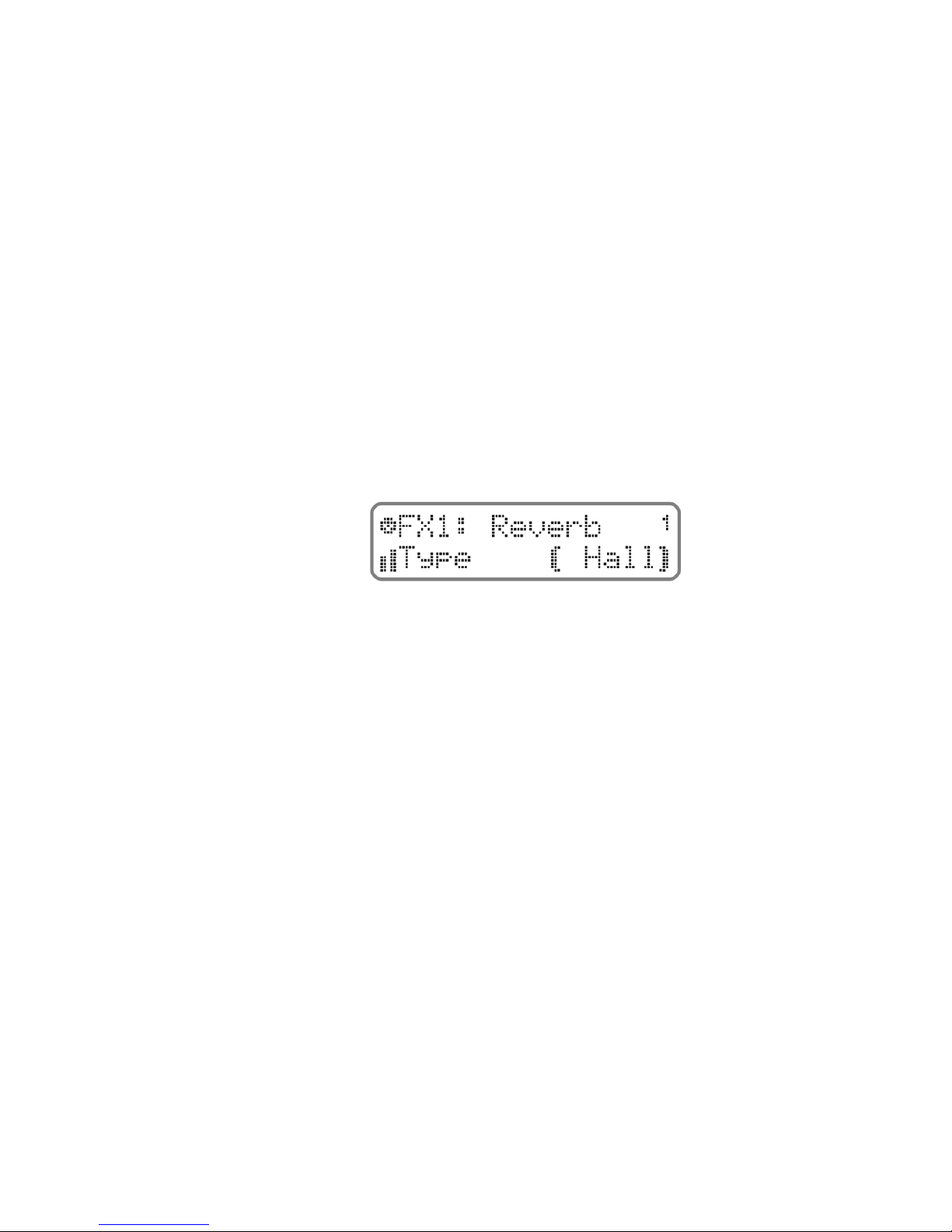
So for example, if we show you again the figure we showed at the start of
this section, you can see that:
the GROUP is “FX1”
the PAGE is “Reverb” (as we are in the effects editing area)
the reverb effect PARAMETER is “Type”
the VALUE is “Hall”, and with the VALUE UP/DOWN buttons and/or the
BIG DIAL you could choose between “Room”, “Stage”, “Plate”…
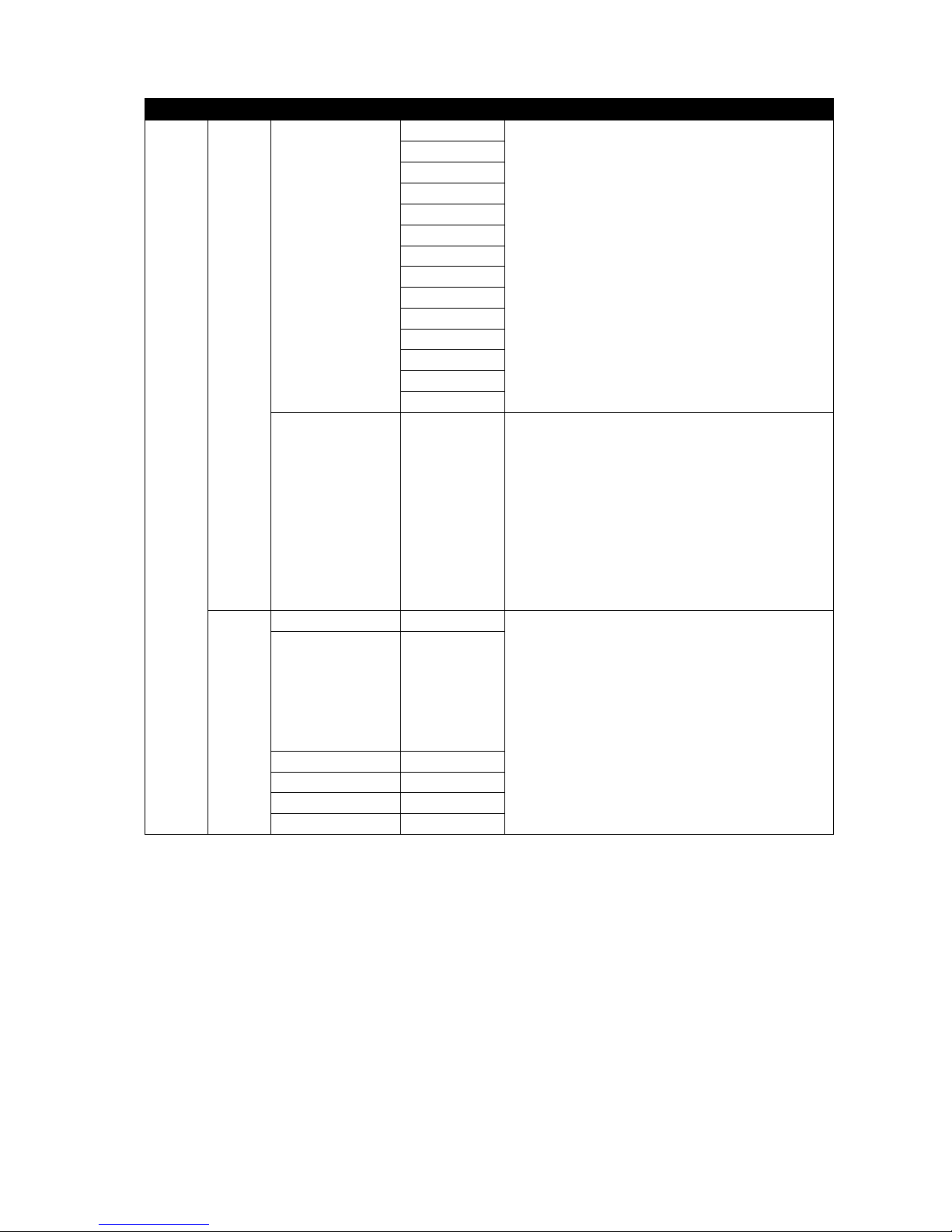
Over the following pages we have laid out all the parameters, which show
the menu structure clearly.

Chromasonic User’s Manual
19
Group Page Parameter Value Description
Off
The FX Slot is turned OFF. NOTE: To choose this state
you can press SHIFT + VALUE DOWN from anywhere
in the list. SHIFT + VALUE UP will reactivate the FX
Slot again. See section 2.2.2 for more details
Reverb Spatial effects such as Halls as Rooms
Delay Multiple echo type effects
ParamEQ For boosting and cutting certain frequencies
Compressor For controlling dynamics, commonly used for “pulling
down” the loudest part of a sound
Limiter A heavy for of compression for “flattening” a signal
and avoid its level to exceed a threshold
Gate
If the signal level falls below a certain point, the
signal is cut completely. Commonly used for making
the quietest passages completely silent to cut out
unwanted noise
Tremolo Modulates the signal volume at a specified speed
and depth, producing a “wobbling” sound
Chorus
Adds one or several voices each with a slight
variation of pitch and delay, creating a double voice
effect
Flanger
Similar to the Chorus, but with very short delays, and
feedback to create a sound with a swirling frequency
pattern
Phaser
It uses an allpass filter to shift the phase of the input
signal whose output is mixed with the original. It
also uses feedback, producing a “whooshing” sound
AutoPan Moves the sound around in the stereo field
WahWah Uses a controllable bandpass filter to create that
classic sound
FX Sel This is where
you select the FX
type to put into this
Slot (as listed on the
right - you pick the
effect using VALUE
UP/DOWN)
Pitch shifter
Up to 4 voices that change the pitch up or down.
They can be also placed individually within the
stereo field
PARAMS
From FX Sel above,
if you press PARAM
UP you will start to
navigate through
the list of
parameters for that
particular effect (See
Table 2)
With VALUE
UP/ DOWN you
can edit the
effect
parameter
values
See section “NAVIGATION” on section 2.2.1 for
details
Active On - Off
Turns the whole FX Slot On / Off. This is the same as
pressing SHIFT+VALUE DOWN from within the FX Sel
list. See section 2.2.2 below for more details
InSel
In L + R
In L
In R
Here you choose the input source for the FX Slot
InLevel 0 - 127 For adjusting the input source volume
OutLevelL 0 - 127 For adjusting the left output volume
OutLevelR 0 - 127 For adjusting the right output volume
FX1
ROUTING
Wet/Dry 0% - 100% Balances the FX Slots processed output with the
input signal it has processed
20
Operating Modes
Group Page Parameter Value Description
Off
Reverb
Delay
ParamEQ
Compressor
Limiter
Gate
Tremolo
Chorus
Flanger
Phaser
AutoPan
WahWah
FX Sel This is where
you select the FX
type to put into this
Slot (as listed on the
right - you pick the
effect using VALUE
UP/DOWN)
Pitch shifter
See above…
PARAMS
From FX Sel above,
if you press PARAM
UP you will start to
navigate through
the list of
parameters for that
particular effect. This
is shown in more
detail in Table 2
With VALUE UP/
DOWN you can
edit the effect
parameter
values
See section “NAVIGATION” on section 2.2.1 for
details
Active On - Off
InSel
In L + R
In L
In R
Exf1 L+R
Efx1 L
Efx1 R
InLevel 0 – 127
OutLevelL 0 – 127
OutLevelR 0 – 127
FX2
ROUTING
Wet/Dry 0% - 100%
See above…
Table of contents
Other SoundArt Recording Equipment manuals

Popular Recording Equipment manuals by other brands

Random*Source
Random*Source SERGE MODULAR AUDIO INTERFACE 2023 user manual

Yamaha
Yamaha DTR2 owner's manual

Innovative Technology
Innovative Technology ITRR-501 instructions

Teac
Teac HD-R1 Compatibility chart

NEXIQ Technologies
NEXIQ Technologies Blue-Link Installation and setup manual

MICRO-EPSILON
MICRO-EPSILON IF2035 Assembly instructions


