SoundGate Simple-fi VIDBMW1V4 User manual
Purpose...
The VIDBMW1V4
allows you to add
up to 2 video
signals (DVD,
VCR, rear-view
camera, game console, etc.) to the factory
navigation systems on the BMW vehicles listed
below.
Note: The VIDBMW1V4 provides video input only. To
input audio signals, you will need an additional
interface (sold separately - see below).
Features...
The VIDBMW1V4 utilizes microprocessor
control, ultra-reliable surface-mount
construction, and advanced firmware design, to
flawlessly match the video signal from the new
sources to the factory system.
The VIDBMW1V4 is also equipped with
brightness, color and contrast adjustments
to allow you to get the best quality picture
possible.
Be Sure To Ask Your Autosound Specialist About
These Other Exciting SoundGate Products...
• Competition-Grade Interfaces for adding amplifiers
• Remote audio control interfaces that let you control aftermarket receivers and CD players from your
factory rear seat, or steering-wheel-mounted audio controls.
• And many others!
wwwwww..ssoouunnddggaattee..ccoomm
Why SoundGate Dealers have the edge...
The technologies used in today’s vehicles are as sophisticated as any laptop computer. At
SoundGate we believe these new technologies are full of opportunities for mobile electronic
dealers across the nation. We make it a high priority to not only research these new systems, but
to understand them and their impact on the aftermarket car audio industry. Armed with this
knowledge, we are well equipped to help you integrate new components into these systems with
our innovative, high-performance interfaces and unparalleled technical support.
VIDBMW1V4
The SoundGate VIDBMW1V4 works in the following BMW vehicles when the vehicle is
equipped with the factory Navigation system:
1996 - 2005 3-Series including M & Z
1997 - 2003 5-Series
9/98 - 2001 7-Series (please see VIDUNIV for 7-series with “I-Drive”)
2004 - 2006 X3
2000 - 2005 X5
2003 - 2006 Z4
2001 - 2003 Z8
Audio input interfaces (one part required if you need to input audio signals also):
SDSBMW - Vehicles without factory DSP, with CD changer
AUXBMWV2 - Vehicles without factory DSP, without CD changer
SDSBMWDSP - Vehicles with factory DSP, with CD changer
AUXBMWDSP - Vehicles with factory DSP, without CD changer
Page 1
If you experience any problems, call SoundGate Technical Support at 800-256-0808
Liability Disclaimer: SoundGate®, Stillwater Designs, Inc., its subsidiaries, or Officers of the corporation
cannot be held liable for damages or injuries caused by, or resulting from the use of this instruction guide or product.
REPAIR OR REPLACEMENT IS THE EXCLUSIVE REMEDY OF THE PURCHASER. ANY IMPLIED WARRANTY ON THIS PRODUCT
INCLUDING MERCHANTABILITY OR FITNESS FOR A PARTICULAR PURPOSE IS LIMITED IN DURATION TO THE DURATION OF
THE WARRANTY(please see the enclosed Limited Warranty document for complete Warranty information). SOUNDGATE
NEITHER ASSUMES NOR AUTHORIZES ANY OTHER PERSON TO ASSUME FOR IT ANY OTHER LIABILITY IN CONNECTION
WITH THE SALE AND USE OF THIS PRODUCT. SOUNDGATE PROHIBITS ANY RETAILER FROM EXTENDING ANY WARRANTY
OR WARRANTIES ON BEHALF OF SOUNDGATE TO ANY PERSON. SOUNDGATE IS NOT RESPONSIBLE FOR ANY INDIRECT,
INCIDENTAL, OR CONSEQUENTIAL DAMAGES.
Strictly adhere to all car manufacturer warnings that pertain to the disassembly, maintenance, or servicing of the vehicle and
any of its associated parts or systems.
SoundGate cannot be held responsible for discrepancies, or inconsistencies that may occur due to vehicle
manufacturing changes.
If you feel that you cannot agree with the above limitations, please return this product to the dealer you
purchased it from, or call SoundGate Customer service at 800-256-0808 for a Return Authorization number, and return the
product to SoundGate for a credit or refund.
Copyright©2004-2008 SoundGate®. All Rights Reserved. SoundGate®is a registered
trademark of Stillwater Designs, Inc. All other trademarks are the property of their
respective owners.
Rev 20080520
Disconnect factory navigation
connector at Nav unit located bhind
amplifier
A. You will be connecting the SoundGate VIDBMW1V4 at
the factory Navigation unit in the trunk, or rear, of
vehicle. Gain access to this location.
B. Disconnect the blue connector at the factory Nav unit,
coming from the navigation system (similar to male
connector on VIDBMW1V4
harness - shown at right). Press the locking tab on the
blue housing adjacent to the black
locking arm, and rotate the locking arm 90° to release
the connector.
Preliminary:
A. Please consult a factory service manual for exact location and disassembly instructions if
you are unsure of the procedure. Pay close attention to any warnings or instructions
regarding working with or around airbags.
B. Turn the ignition key to the “Off” position.
C. Make sure the car’s factory radio is turned to the “Off” position.
Step
3
Install the video source unit(s)
Referencing the instructions provided with your video source units, install the
components in the desired locations. Route the video cables and any required
power, ground, and trigger wires to the
factory amplifier location for connection to the VIDBMW1V4.
Step
2
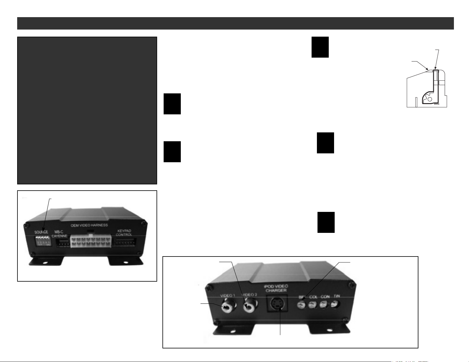
Verify DIP switch settings on VIDBMW1V4 module
On the end of the module as shown in the diagram at left below, you will see
a red 5-position DIP switch. Verify that the switches are set
as follows (On = down, Off = up):
2, 4 = on 1, 3 and 5 = off.
Step
1
VIDBMW1V4 INSTALLATION INSTRUCTIONS
Connect VIDBMW1V4 harness to Nav unit behind amplifier
A. Check the position of the black locking arm on the blue male connector of the
VIDBMW1V4 harness and make certain it is in the unlocked position.
B. Plug the blue male connector on the VIDBMW1V4 harness into the connector port
vacated in Step 3 above. Rotate the locking arm to secure the connector. Do not force
the locking arm or it may break.
C. Plug the blue male connector disconnected in Step 3 above, into the blue and black
female connector on the VIDBMW1V4 harness. Rotate the locking arm to secure the
connector.
Step
4
Locking
Tab
Locking Arm
(locked position)
Navigation Connector
Figure 1
IMPORTANT WARNING!
It is illegal in all 50 U.S. states, and in most Canadian provinces,
to have real time video (TV broadcast, VHS, DVD video, etc.) in
view of the driver.
IF YOU ARE GOING TO USE THE SOUNDGATE VIDEO INTERFACE
FOR ANYTHING OTHER THAN INTERFACING A REARVIEW
CAMERA SYSTEM, THE BLUE INTERLOCK WIRE ON THE
SOUNDGATE VIDEO MODULE MUST BE PROPERLY CONNECTED TO
PREVENT THE DRIVER VIEWING REAL TIME VIDEO WHILE THE
VEHICLE IS IN MOTION.
We do not want to put our dealers in a position of liability, nor
our customers in danger in the event of an accident due to
driver distraction.
If you do not intend to comply with applicable law, please return
the SoundGate video module to the dealer it was
purchased from, or to SoundGate if it was purchased direct. Call
SoundGate Customer Service at 800-256-0808 for a Return
Authorization.
Connect remaining wires
Referencing Figure 2 and 3 on page 3, connect the remaining wires on the
VIDBMW1V4 harness. One of the options shown will cover most installations.
Consult the documentation that came with your video component to
determine which of these is appropriate for your installation.
Step
5
DIP switches
Inputs and Controls
Video Input 2
Video iPod Input
Video Input 1
Brightness/Color/Contrast/Ti
nt Adjustments
Inputs and Controls

Rearview camera: If you have installed a rearview camera system, and have the
camera video signal connected to
Video 1, with the grey Source 1 trigger wire fed from the back up light circuit, when you
put the vehicle in reverse, the VIDBMW1V4 will automatically switch the screen display
to the rearview camera.
Adjusting picture quality: VIDBMW1V4 module is equipped with brightness, color and
contrast adjustments. Note: Adjustments affect both Video 1 and 2 equally (cannot be
set individually).
VIDBMW1V4 OPERATION
30
86 85
87a
87
+12 Volt ACC “trigger”
from Source 2 (if present)
Bosch Relay
(not included)
Ground
Ground
Ground “trigger” from
Source 2 (if present)
Black - trigger wire
to activare Source 2
White 7-pin connector
with single black wire
Manual Latching-type
single pole, single throw
switch (not included) Chassis ground
30
86 85
87a
87
Ground “trigger” from
Source 1 (if equipped)
Bosch Relay
(not included)
+12 Volt ACC (switched)
Manual Latching-type
single pole, single throw
switch (not included)
+12 Volt from back up
light circuit (hot when
vehicle is in reverse)
OR
+12 Volt “trigger” from
Source 1 (if equipped)
White 16-pin
connector
Red
Black
Blue
+12 Volt ACC (switched)
Chassis Ground
Interlock - ground from
hand brake (video
interlock)
Grey trigger wire
to activate Source 1
+12 Volt ACC (switched)
Figure 3 - Source 2 Activation Wiring
Figure 2 - Source 1 Activation, Power, and Ground Wiring
Page 3
VIDBMW1V4 INSTALLATION INSTRUCTIONS
Finish installation
Once testing is done and the system is functioning properly, reinstall all trim
panels removed during installation. Installation is complete!
Step
7
Reinstall radio and test operation
A. If you have installed a rearview camera, start the vehicle, turn on the radio and
navigation system and put the vehicle in reverse. The navigation display should change
to show the view from the camera. Shifting the vehicle out of park should return you to
the navigation display. If necessary, adjust the brightness, color and contrast with the
controls on the VIDBMW1V4.
B. If you have installed a video system, with the vehicle in park gear, and the
parking brake on, activate the video source. The navigation display will change to show
the video source.
C. With the video source active and playing, test the video interlock by taking off the
parking brake. The navigation display should return.
Step
6
Other SoundGate Car Stereo System manuals

Popular Car Stereo System manuals by other brands


Sony
Sony CDXGT530UI - CD Receiver MP3/WMA/AAC Player Specifications

Metra Electronics
Metra Electronics 95-9607B installation instructions

Kenwood
Kenwood KDC-W6031 instruction manual

JVC
JVC KD-SH909R instructions

Parrot
Parrot CD/MP3 Hands-free Receiver user manual

Sony
Sony MEX-BT3700U operating instructions