Southwest Microwave 385 User manual
Southwest Microwave Model 385
Outdoor Microwave Transceiver System
100 to 400 ft (30 to 122 m) Detection Range
Features:
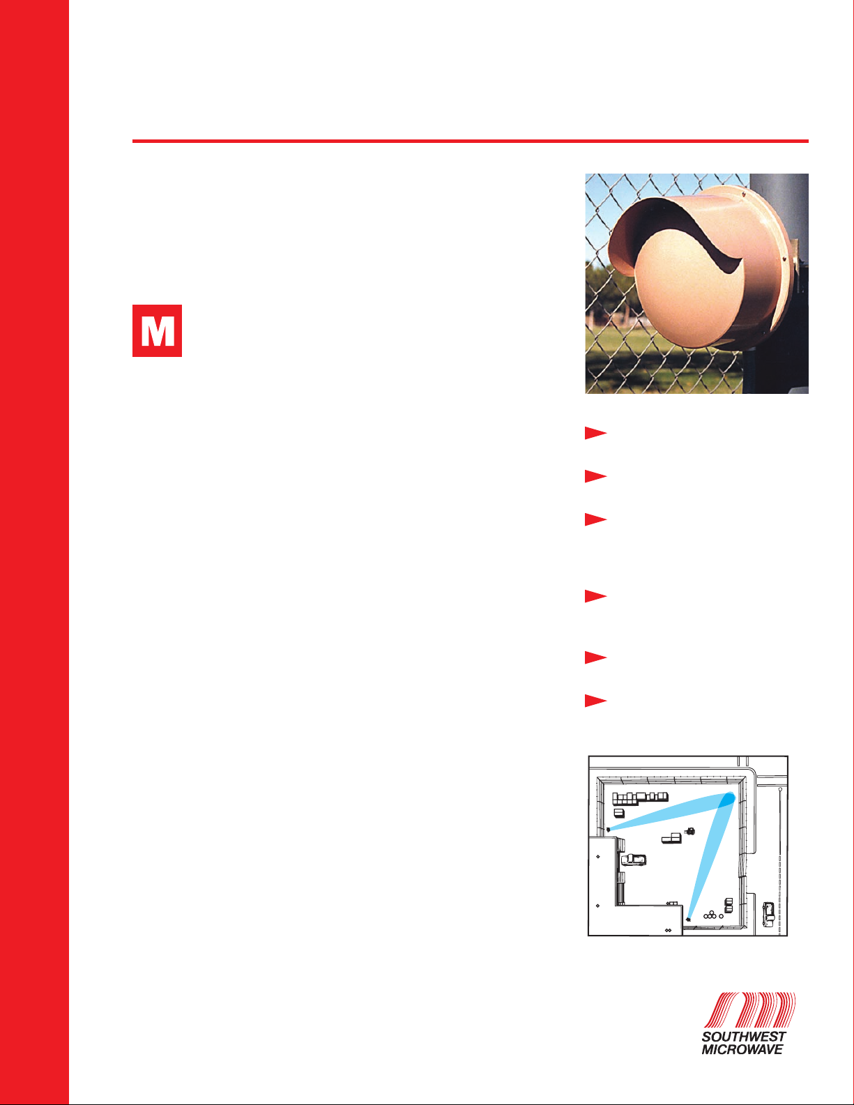
odel 385 K-Band Outdoor Microwave Transceiver provides
reliable three dimensional protection in outdoor environments.
Sensitive, field-adjustable detection circuitry is capable of
detecting the human intruder while walking running, or crawling on hands
and knees at a distance up to 400 feet (122 m) from the transceiver.
A patented* Range Cutoff (RCO) Circuit positively rejects all microwave
targets beyond a preselected range. This unique capability makes Model
385 immune to alarms from any object outside the RCO distance, even very
large microwave targets such as semitrailers, trees, trains or aircraft.
Operating at K-band, which is much less crowded than X-band, Model 385
is inherently less susceptible to outside interference form airport landing
systems, aircraft radar, and other microwave intrusion systems. Because its
K-band microwave frequency is 2.5 times higher than the X-band, the mul-
tipath signal generated by an intruder is also 2.5 times higher and detection
of slow-moving intruders is correspondingly better.
Model 385 is also equipped with a patented Zero-Range Suppression (ZRS)
Circuit which reduces the amplitude of any microwave target which is at very
close range. This circuit dramatically reduces nuisance alarms from rain,
vibration, birds and windblown objects. Neither the RCO nor the ZRS circuit
affects detection pattern.
A Built-In Multiplex System allows the Model 385 to operate in close proximity
with other Southwest Microwave Transceivers and T/R Links without mutual
interference. For multiplexed operation, a synchronizer wire (twisted pair) is
connected to each sensor. Any sensor or external clock is connected as
“master” and all other sensors are connected as “slaves.” For a group of
up to sixteen sensors, only one sensor will operate at a given time.
Setup and adjustment of Model 385 is easily accomplished. Aim the trans-
ceiver into the area to be protected, apply power and allow a few minutes
to establish a reference level for reflected signals from the illuminated area.
Select the desired RCO distance 100 to 400 ft. (30 to 122 m) and perform
a walk test to determine optimum setting for sensitivity control.
Model 385 may be mounted to any solid surface by means of a lock down
swivel mounting bracket supplied with each unit. This swivel mount allows
circular rotation of up to 20
o
in any direction. Mounting bracket will also
mount to solidly based 3.5 or 4 inch (8.9 or 10.2 cm) O.D. post.
Model 385 is designed for use with Southwest Microwave T/R Links which
establish three-dimensional detection patterns, up to 1500 feet (450 m)
long, between transmitter and receiver.
Model 385
Outdoor Microwave Transceiver
Outdoor K-Band Volumetric
Detection to 400 Feet (122
m)
Resistant to Aircraft Radar and
Airport Radar Interference
Continuously Variable Range
Cut-Off Circuit Prevents Alarms
from Moving Objects Beyond a
Preselected Range
Zero-Range Suppression Circuit
Reduces Effects of Rain, Vibra-
tion, and Windblown Objects
Built-In Multiplex System for
Multiple Sensor Operation
Plug-In Test Meter Provides
Quick Set-up

Pattern
Model 385 provides a detection pattern with a maxi-
mum range of 400 feet (122 m) and a maximum width
of 20 feet (6 m). Adjustment of the sensitivity control
can reduce the pattern to approximately 100 feet (30 m)
in length by 3 feet (.9 m) in width. Horizontal and vertical
antenna beamwidth is approximately 3.8 degrees. These
distances are for a mounting height of 3-4 feet (.9-1.2 m);
other mounting heights will reduce the maximum range.
Detection pattern and RCO distances are shown below.
Typical Horizontal Pattern
Dimensions
Operation
Model 385 transmitter radiates a controlled pattern of
microwave energy into the protected area. Under normal
conditions (no intrusion), the receiver establishes a refer-
ence level based on signals reflected from the protected
area. Motion by an intruder causes the received signal to
change relative to the established reference level and an
alarm is generated.
The unique Range Cut-Off Circuit positively limits detection
beyond a field-selected distance
of
100
to
400
feet (30-122
m).
The RCO distance remains fixed and is not affected by the
sensor’s sensitivity adjustment for desired area of coverage.
Model 385 will alarm on a human-sized target running, walking
or crawling on hands and knees through the pattern, and is
relatively insensitive to rain, snow, vibration, and small wind-
blown objects. Area of coverage may be reduced in extreme
environments for additional reliability.
For detailed information on application, installation, and
adjustment consult the Model 385 Technical Manual. Care-
ful installation and alignment is required for trouble-free
operation.
10.6 in.
(270 mm)
DIA.
6.0 in. (152 mm)
4 in. (102 mm) U-bolt standard
(Post should be 4 in. (102mm) O.D.)
3.5 in. (89 mm)
10.125 in.
(257 mm)
20
o
MAX TILT
ANY DIRECTION
MOUNTING HOLES
4.5 in. (114 mm)
4.0 in. (102 mm)
2.81 in. (71 mm)
Cut-offActive
(top view)
100 ft. (30 m) min. 400 ft. (122 m) max.
RCO Point Continuously Variable
Model 385
Outdoor Microwave Transceiver
Specifications
Equipment supplied
Model 385 K-Band Outdoor Microwave
Transceiver and Universal Swivel Ball Mounting Bracket.
Detection range Variable from 100 feet (30.5 m) to
400 feet (122 m). Varies somewhat with site reflectivity.
Detection width Varies with range, 3 feet (0.91 m)
to 20 feet (6.1 m). Varies somewhat with site reflectivity.
Target size
77 pound (35 kg) human walking, running,
hands and knees crawling or jumping. Prone crawling or rolling
77 pound (35 kg) human or 30 cm metal sphere may be de-
tected at shorter ranges with special site preparation.
Target velocity 0.2 ft/sec to 26 ft/sec (0.6 m/sec
to 8.0 m/sec).
Probability of detection 0.99 minimum on 0.8 m
square meter target, based on equipment S/N ratio.
Self-supervision
1) Antenna blockage causes constant alarm.
2) Remote test checks entire transceiver circuit.
3) No loss of detection upon loss of sync.
Range cutoff Targets will not be detected beyond
a field-selected range (100 to 400 feet).
Radiated output 32 milliwatts peak at 24.125 GHz.
Spurious emissions Conforms to F.C.C. Regulation
Part 15 (USA). FCC Identifier CA6385
Sync selection Internal or external.
DC input 11.0 to 14.5 VDC, 160 mA nominal,
220 mA synchronized.
Alarm relay contacts SPDT-Form C, 2 amps at 28 VDC.
Tamper switch SPDT-Form C, 2 amps at 28 VDC.
LED indicators
1) Power “ON” 2) Alarm 3) SYNC lock.
Remote monitor External MS connector for connection
of RM83 Performance Test Set.
Operating environment
- 30
o
F to + 150
o
F (- 35
o
C to + 66
o
C)
0
-
100% relative humidity. (Heater recommended below 0
o
F.)
Shipping weight 10 lbs (4.5 kg) total.
How to Order
Specify Model 385. Order
optional accessories by model
number and description.
Specifications subject to
change without notice.
Southwest Microwave, Inc.
www.southwestmicrowave.com
9055 South McKemy Street - Tempe, Arizona 85284-2946 USA • Telephone 480
-
783
-
0201
•
FAX 480
-
783
-
0401
European Offices:
Southwest Microwave Ltd.
•
Suite 1, Deer
Park Business Centre
•
Woollas Hill,
Eckington,
Pershore,
Worcestershire
•
WR10 3DN, UK
•
TEL: +44 (0) 1386 75 15 11
•
FAX: +44 (0) 1386 75
07
05
7/06
Other Southwest Microwave Transceiver manuals


