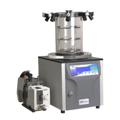
SP Scientific Freezemobile Series User manual

F
REEZE
D
RYER
O
PERATOR
’
S
M
ANUAL
V
IR
T
IS
F
REEZEMOBILE
25L
AND
35L
F
REEZE
D
RYERS


Rev 005, 02/12 i
© SP Scientific 2012
Copyright © 2012 SP Scientific. All marks herein are used under license.
All brand or product names mentioned may be trademarks or registered trademarks of their respective
companies.
Part Number 386142
Rev 005, 02/12
SP Scientific 815 State Route 208 3538 Main Street
Gardiner, NY 12525 USA Stone Ridge, NY 12484
USA
(800) 431-8232
(845) 255-5000
SP Scientific Service (877) 548-4666
SP Scientific Service Fax (845) 687-0024
Website http://www.spscientific.com/
This Freeze Dryer Operator’s Manual contains confidential and proprietary information of SP Scientific
and may be used only by a recipient designated by and for purposes specified by SP Scientific.
Reproduction of, dissemination of, modifications to, or the creation of derivative works from this Freeze
Dryer Operator’s Manual, by any means and in any form or manner, is expressly prohibited, except with
the prior written permission of SP Scientific. Permitted copies of this document must retain all proprietary
notices contained in the original.
The information in this document is subject to change without prior notice. Always confirm with SP
Scientific that you are using the most current version of this document. SP Scientific is free to modify any
of its products and services, in any manner and at any time, notwithstanding the information contained in
this document.
THE CONTENTS OF THIS DOCUMENT SHALL NOT CONSTITUTE ANY WARRANTY OF ANY KIND,
EITHER EXPRESSED OR IMPLIED, INCLUDING BUT NOT LIMITED TO THE IMPLIED WARRANTIES
OF MERCHANTABILITY AND/OR FITNESS FOR A PARTICULAR PURPOSE OR GIVE RISE TO ANY
LIABILITY OF SP SCIENTIFIC, ITS AFFILIATES OR ITS SUPPLIERS.
The terms and conditions governing the use of this Freeze Dryer Operator’s Manual shall consist of those
set forth in written agreements with SP Scientific.

ii Rev 005, 02/12
© SP Scientific 2012
Important Symbols
WARNING!
INJURY OR EVEN DEATH
MAY RESULT IF A
RECOMMENDATION MARKED
WITH THIS SYMBOL IS NOT
HEEDED.
CRUSH HAZARD. KEEP HANDS
CLEAR WHEN OPERATING DOOR.
ELECTRIC SHOCK DANGER!
USE APPROPRIATE CAUTION
TO AVOID INJURY OR DEATH.
CORROSIVE CHEMICAL. WEAR
SUITABLE GLOVES, SAFETY
GLASSES, AND PROTECTIVE
CLOTHING.
BURN DANGER! POTENTIALLY
HOT SURFACE. USE
APPROPRIATE CAUTION.
PROPERTY CAUTION! TO PREVENT
DAMAGE TO CHAMBER EQUIP-
MENT AND/OR LOAD, ADHERE TO
PROCEDURES MARKED BY THIS
SYMBOL.
DO NOT STORE FLAMMABLE
MATERIALS IN CHAMBER.
PRACTICAL OPERATING TIP.
THESE RECOMMENDATIONS
STREAMLINE UNIT OPERATION
AND PREVENT COMMON
OPERATOR ERRORS.
WEAR SAFETY GLASSES. EXPLOSIVE MATERIALS HAZARD!
KEEP OBJECTS AWAY FROM HEAT.
Freeze Dryer Safety Warnings
Always assume that shelf, condenser and internal parts may be very cold or very hot. Wear protective equipment
to avoid burns.
Always ensure that only an authorized technician services the refrigeration, heat transfer, vacuum and electrical
systems.
Always ensure that refrigeration air intake is clear and clean.
Always ensure vacuum pump exhaust is properly ventilated and/or contained.
Always practice team lifting when moving heavy equipment.
Always use a maximum one pound regulator if backfilling from an inert gas source.
Always wear safety glasses when using glass flasks.
Do carefully read the entire instruction manual before attempting to operate the freeze dryer.
Do verify that the electric service and other utilities match the unit’s requirements before connecting to power.
Never allow hand or body contact with open vacuum ports.
Never clean with solvents. Use mild detergent and water only.
Never operate the unit without all covers in place.
Never pressurize chambers. Laboratory freeze-drying systems are designed for vacuum only.
Never stopper vials unless the chamber door is tightly closed.
Never use acrylic closures if they are cracked or crazed.
Never use with toxic, corrosive, flammable or organic materials unless special precautions are in place to
prevent injury to personnel or damage to equipment.

Rev 005, 02/12 iii
© SP Scientific 2012
Warranty Information (VirTis Lyophilizers)
VirTis Freezemobile 25L and 35L Lyophilizers are is warranted by SP Scientific to be free of defects in
material and workmanship when operated under normal conditions as specified in the instructions
provided in this manual. Please take this opportunity to locate the serial tag on your new VirTis
Freezemobile 25L and 35L and record the information below for future reference. SP Scientific also
recommends that you complete and return your unit’s warranty registration card.
Model Number
Serial Number
Part Number
Limited Warranty
SP Scientific (the “Company”) warrants each of its products against any defects in material or
workmanship, provided that the product is used in a reasonable manner under appropriate conditions and
consistent with the applicable operating instructions, for a period of 12 months from the date of installation
or 15 months from the date of shipment (whichever comes first).
The obligation of the Company shall be, at its option, to repair or replace, without charge any parts that
prove to be defective within the warranty period, if the purchaser notifies the Company promptly in writing
of such defect. The Company shall not be responsible for labor charges payable with respect to persons
other than Company employees. Replacement or repair of parts pursuant to this warranty shall not in any
way extend the original warranty period. The Company will not be responsible for any unauthorized
repairs, replacements or product modifications, nor will it be responsible for any product failures resulting
from such unauthorized repairs, replacements or product modifications negligently or otherwise made by
persons other than Company employees or authorized representatives of the Company.
THE COMPANY DOES NOT MAKE AND EXPRESSLY DISCLAIMS ANY WARRANTY OF
MERCHANTABILITY OR FITNESS FOR A PARTICULAR PURPOSE OR ANY OTHER WARRANTY,
EXPRESSED OR IMPLIED, WITH RESPECT TO THE SALE, INSTALLATION, DESIGN OR USE OF ITS
PRODUCTS. ADDITIONALLY, THE COMPANY SHALL NOT BE LIABLE FOR ANY CONSEQUENTIAL
DAMAGES RESULTING FROM THE USE OF OR ANY DEFECTS IN ITS PRODUCTS.
The Company’s employees are available to provide general advice to customers concerning the use of
the Company’s products; however, oral representations are not warranties with respect to particular
products or their uses and may not be relied upon if they are inconsistent with the relevant product
specifications for the items set forth herein.
Notwithstanding the above, the terms and conditions set forth in the Company’s formal sales contracts
shall be controlling and supersede any inconsistent terms contained herein, and any changes to such
contracts must be made in writing and signed by an authorized executive of the Company.

iv Rev 005, 02/12
© SP Scientific 2012

Rev 005, 02/12 v
© SP Scientific 2012
Contents
Important Symbols ............................................................................................................................................... ii
Freeze Dryer Safety Warnings............................................................................................................................. ii
Warranty Information (VirTis Lyophilizers) .......................................................................................................... iii
Introduction .................................................................................................................1
Overview..............................................................................................................................................................1
Key Features........................................................................................................................................................1
Installation and Startup ............................................................................................... 3
Initial Inspection ...................................................................................................................................................3
Service Connections ............................................................................................................................................3
Freezemobile Setup.............................................................................................................................................4
Sentry 2.0 Controls ..................................................................................................... 7
Overview..............................................................................................................................................................7
LED Wave Display (Qualitative Reference) .........................................................................................................7
Button Functions ..................................................................................................................................................8
Up/Down (±) Buttons .......................................................................................................................................8
MENU Button ..................................................................................................................................................8
COND Button ..................................................................................................................................................8
VAC Button......................................................................................................................................................8
AUTO Button ...................................................................................................................................................8
DEFR Button ...................................................................................................................................................8
LCD Display Functions ........................................................................................................................................9
Main Menu ...........................................................................................................................................................9
Vacuum Control...............................................................................................................................................9
Bath (Optional) ..............................................................................................................................................10
Purge (Optional) ............................................................................................................................................10
Heat (Optional) ..............................................................................................................................................10
User Options ......................................................................................................................................................10
Vacuum Control.............................................................................................................................................10
Temperature Units.........................................................................................................................................11
Vacuum Units ................................................................................................................................................11
Relay Test .....................................................................................................................................................11
Vacuum Pump Maintenance .........................................................................................................................11
Alarms................................................................................................................................................................12
Setpoints ............................................................................................................................................................12

Contents
V
irTis Freezemobile 25L and 35L
vi Rev 005, 02/12
© SP Scientific 2012
Condenser Temperature ...............................................................................................................................13
Maintenance Menu ............................................................................................................................................13
Factory Options .............................................................................................................................................14
Interstage Control..........................................................................................................................................14
Calibration .....................................................................................................................................................15
Basic Operation......................................................................................................... 17
Getting Started...................................................................................................................................................17
Product Preparation: Flask / Manifold Drying.....................................................................................................17
Product Preparation: Manifold Shelf Drying .......................................................................................................17
Quickseal Valves ...............................................................................................................................................18
Operation Instructions........................................................................................................................................19
Meltback.............................................................................................................................................................20
Preventing Glassware Breakage........................................................................................................................20
Product Dryness End Point ................................................................................................................................21
Stoppering (Optional) .........................................................................................................................................21
Optional Components ............................................................................................... 23
Overview............................................................................................................................................................23
Manifolds............................................................................................................................................................23
Shelf Racks........................................................................................................................................................24
Electric Purge.....................................................................................................................................................25
Shell Bath...........................................................................................................................................................25
Liquid Nitrogen Trap ..........................................................................................................................................26
Defrost...........................................................................................................................................................27
Filter Trap...........................................................................................................................................................28
Degassing Filter Trap Cartridges...................................................................................................................28
Glass Condenser Door ......................................................................................................................................29
General Maintenance................................................................................................ 31
Overview............................................................................................................................................................31
Vacuum System.................................................................................................................................................31
Vacuum Pump...............................................................................................................................................31
Changing Vacuum Pump Oil .........................................................................................................................31
Gas Ballast Valve on the Vacuum Pump.......................................................................................................32
Vacuum Tubing and Gaskets ........................................................................................................................32
Quickseal Valves...........................................................................................................................................33
Refrigeration System .........................................................................................................................................34
Air-Cooled Condenser...................................................................................................................................34
Condenser Chamber .....................................................................................................................................34
Acrylic Parts .......................................................................................................................................................35
Chemical Resistance Chart ...........................................................................................................................35
Appendix A: Troubleshooting .................................................................................... 37

V
irTis Freezemobile 25L and 35L Introduction
Rev 005, 02/12 vii
© SP Scientific 2012
Vacuum Leak Testing on Research Units..........................................................................................................37
Testing the Vacuum Pump and Gage ...........................................................................................................37
Testing the Base Unit ....................................................................................................................................38
Testing the Manifold ......................................................................................................................................38
Testing the Condenser ..................................................................................................................................38
Product Melting ..................................................................................................................................................39
Appendix B: Stainless Steel Cleaners....................................................................... 41


Rev 005, 02/12 1
© SP Scientific 2012
Chapter
1
Introduction
Overview
The Freezemobile Series Freeze Dryers have been carefully designed to provide
years of dependable, trouble-free service. In keeping with our traditions of quality,
reliability and technical innovation, your new Freezemobile offers a wide variety of
features for convenient, flexible and efficient operation.
Key Features
Sentry 2.0 controller with single button auto-start, full function control and
precise vacuum regulation.
Stainless steel, smooth-walled condenser with clear acrylic door for full
visibility.
Intuitive graphic display with points representing condenser temperature and
vacuum levels.
Audible and lighted display alarms to notify you when the system has not
reached required setpoints in the configuration.
Vacuum brake solenoid (VBS) valve maintains system vacuum pressure and
prevents oil from backstreaming into the system in the event of a power
failure or improper shutdown.
Removable front and side panels for easy access to the refrigeration system
and components.
Hot gas defrost for easy ice removal and rapid turnaround time.
High-efficiency CFC-free refrigeration system capable of reaching condenser
temperatures as low as -85 °C.
Note: SP Scientific builds each unit according to the options purchased. Review the standard
selections, as well as the relevant optional sections of this manual.
The Freezemobile Series is also designed to operate with a wide variety of product
manifold chambers. For more information, refer to Chapter 5: Optional Components.

Introduction
V
irTis Freezemobile 25L and 35L
2 Rev 005, 02/12
© SP Scientific 2012

Rev 005, 02/12 3
© SP Scientific 2012
Chapter
2
Installation and Startup
Initial Inspection
Inspect the contents of your shipment immediately upon arrival. Check packing
material for possible small accessory items. DO NOT ACCEPT damaged shipments
from a carrier without a signed notification of damages.
If concealed damage and/or loss is discovered, contact the freight carrier immediately.
Keep the contents, packing material and related paperwork intact until the written
report is obtained.
If your shipment is “FOB Destination” file your claim with SP Scientific and
include the inspection report and any other supporting documents.
If your shipment is “FOB Shipping Point” file your claim with the freight carrier
and include the inspection report and any other supporting documents.
Note: SP Scientific will cooperate in the matter of collecting your claim, but is not responsible
for the collection or free replacement of the material. When possible, replacement parts will be
shipped and invoiced to you, making them a part of your claim.
Service Connections
Ensure that the outlet you intend to use meets the service requirements listed on the
serial tag of your unit. The serial tag is typically located on the front and rear of the
lyophilizer.
CAUTION! ONLY A QUALIFIED ELECTRICIAN SHOULD CONNECT THE UNIT TO THE AVAILABLE
ELECTRICAL SUPPLY.
SP Scientific ships Freezemobile units without a plug to locations where electrical
connections vary from standard U.S. requirements. The line cord has three individual
conductors inside the outer jacket.
To make the appropriate plug connection:
1. Trim back enough of the jacket to facilitate installation of the plug.
Serial Tag Example

Installation and Startup
V
irTis Freezemobile 25L and 35L
4 Rev 005, 02/12
© SP Scientific 2012
2. The three individual conductors now exposed are BROWN, BLUE, and
GREEN with a YELLOW tracer.
3. Connect the BROWN wire to the line (hot) terminal on the plug.
4. Connect the BLUE wire to the neutral terminal.
5. Connect the GREEN/YELLOW wire to the ground terminal.
Freezemobile Setup
1. Position the Freezemobile unit so that it rests firmly and level on the floor.
Allow yourself sufficient space to easily connect the unit and ensure that the
area around the unit provides for adequate air circulation. The back of the
Freezemobile should be at least four inches away from the wall.
Note: For efficient operation, maintain room temperature at 20 °C (68 °F). Warmer
ambient temperatures may negatively affect system performance.
2. The refrigeration system compressors may be mounted on shock absorbent
springs. Check to see if you have compressor spring mounts. If so, use a ½-
inch wrench to loosen the shipping hex nuts on the spring mount bolts. These
are tightened prior to shipment. Turn each shipping hex nut counterclockwise
until the top of the nut is flush with the top of its bolt. This will float the
compressor on the springs and prevent vibration from extending to the
cabinet. To reach all spring mount bolts, you may need to work through the
back, front grille and/or side panels.
3. If you purchased a vacuum pump with your unit, it will ship pre-installed inside
the cabinet. Remove the shipping plug in the exhaust port and ensure that the
vacuum pump is plugged into the IEC receptacle marked VACUUM.
4. Check the vacuum pump oil level. The oil should read between the center and
top of the sight glass when the pump is off and near the top line while the
pump is in use. Add oil only if necessary.
Note: The vacuum pump is shipped with oil in it. Do not overfill.
Pump vapors can be dangerous in the laboratory and are typically not
tolerated in a cleanroom. SP Scientific suggests that you use an adequate
vacuum pump exhaust system. You can use an exhaust fume hood or vent
the pump to the outside of the building. Exhaust lines should travel
horizontally from the pump to a “T” with a drainable trap, and then 90 degrees
vertically to an outside vent. Place trap as close to the pump as possible.
Note: Oil mist eliminators are available from SP Scientific.

V
irTis Freezemobile 25L and 35L Installation and Startup
Rev 005, 02/12 5
© SP Scientific 2012
5. Open the condenser door. A very light film of high-vacuum grease has been
applied to the front contact surface of the condenser gasket prior to factory
testing. Only a light sheen should be visible on the surface. Check often to
ensure that this film is present.
Note: Never grease the inside of the gasket where it grips the condenser lip.
6. Ensure that the voltage, phase, frequency and amperage listed on the
Freezemobile serial tag match the available power supply.
7. Switch the main power switch to the On position. The Sentry 2.0 display will
illuminate.

Installation and Startup
V
irTis Freezemobile 25L and 35L
6 Rev 005, 02/12
© SP Scientific 2012

Rev 005, 02/12 7
© SP Scientific 2012
Chapter
3
Sentry 2.0 Controls
Overview
The Sentry 2.0 is the control center for the Freezemobile Series. Driven by a powerful
microprocessor, the Sentry 2.0 allows for custom programming, includes a detailed
display, and offers flexibility with a wealth of configurable features, as well as
intuitively easy operation.
The Sentry 2.0 front panel consists of the following:
An LED wave display, which allows you to assess the status of the system
quickly and easily.
Tactile buttons located on the membrane, which allow you to activate specific
functions and navigate through the menus within the LCD display.
An LCD display, which shows the status of the unit and allows you to adjust
the alarm and control parameters, as well as modify system configurations.
LED Wave Display (Qualitative Reference)
1. Condenser Temperature
The LEDs on the bottom wave represent the following temperatures:
LED Temperature (°C) Color
1 10 Red
2 0 Red
3 -10 Red
4 -20 Amber
5 -30 Amber
6 -40 Green
7 ≤-50 Green

Sentry 2.0 Controls
V
irTis Freezemobile 25L and 35L
8 Rev 005, 02/12
© SP Scientific 2012
2. Vacuum
The LEDs on the top wave represent the following vacuum setpoints:
LED Vacuum (mT) Color
1 2000 Red
2 1000 Red
3 500 Amber
4 200 Amber
5 100 Green
6 50 Green
7 ≤20 Green
Button Functions
Up/Down (±) Buttons
The Up/Down (±) buttons allow you to navigate the menus and increase or decrease
setpoint values contained within those menus.
MENU Button
The MENU button performs a number of functions. During an alarm condition,
pressing MENU will temporarily silence (but not clear) the alarm. When viewing the
Synoptic screen, the MENU button will display the Main Menu.
The MENU button also acts as an enter key, activating the selected option. To return
to a previous menu, highlight the carat (^) at the top left corner of the LCD screen and
press the MENU button.
COND Button
The COND button activates the refrigeration system. This provides system cooling for
vapor condensing.
VAC Button
The VAC button enables the vacuum pump and opens the vacuum brake solenoid
(VBS) valve, allowing the system to be evacuated. Vacuum level control options can
be programmed from the User Options screen.
Note: If your vacuum pump is not connected to the IEC plug on the rear of the Freezemobile
unit, the VAC button will not control your pump. See your pump manual for operation
instructions.
AUTO Button
The AUTO button will start the refrigeration and vacuum systems in a set sequence.
The condenser will first cool to the condenser setpoint. Once the setpoint is achieved,
the vacuum pump will energize and begin evacuating the system.
DEFR Button
The DEFR button activates the condenser defrost function. Hot gas is directed toward
the condenser walls to quickly loosen ice.
Note: If any other function is enabled, defrost mode is disabled.

V
irTis Freezemobile 25L and 35L Sentry 2.0 Controls
Rev 005, 02/12 9
© SP Scientific 2012
LCD Display Functions
By default, the LCD display shows the system Synoptic screen. The synoptic screen
gives a visual representation of the current operation and status of the unit. Alarm
messages, run time and system status are displayed.
Main Menu
Pressing the MENU button while on the Synoptic screen displays the Main Menu. If
the unit goes idle (i.e., no input after three minutes), the system will default back to the
Synoptic screen.
Main Menu
User Options
Alarms
Setpoints
Vacuum Control 0000
Purge Off
Bath Off
Heat Off
Note: Temperature and vacuum control functions are disabled except when the Synoptic
screen is displayed. Bath and Heat functions are not available simultaneously.
Navigation through menu screens is accomplished using the Up/Down (±) arrow
buttons, as well as the MENU button. The Up/Down (±) buttons allow you to scroll the
cursor to the desired function. Setpoints are also modified using these buttons. The
MENU button is used to select the highlighted item. The ^ symbol located in the upper
left corner of the screen returns you to the previous screen. The > symbol signifies a
submenu which can be accessed with the MENU button.
Vacuum Control
The Vacuum Control field displays the current vacuum level control setpoint. To
change the setpoint, use the Up/Down (±) buttons and navigate to the Vacuum
Control field. Press and hold the MENU button. Use the Up/Down (±) buttons to adjust
the vacuum control. Press MENU to enter the new setpoint.
Vac OFF
30mT
Condenser
-67.8 °C
ON
00:32Status
Cooling
Ambient 19.8 °C
X
VBS STATUS:
X = OFF
> = ON
P
PURGE OPTION:
FLASHES WHEN ON
UNIT STATUS:
COOLING
VACUUM
OFF
FLASHING ALARMS:
VACUUM ALARM
COND. ALARM
POWER OUTAGE
AMBIENT TEMPERATURE
CURRENT CONDENSER TEMP
CONDENSER STATUS:
OFF
ON
AUTO
DEFROST
VACUUM STATUS:
OFF
ON
CURRENT SYSTEM VACUUM
RUN TIMER
BATH TEMPERATURE
Bath
-50 °C

Sentry 2.0 Controls
V
irTis Freezemobile 25L and 35L
10 Rev 005, 02/12
© SP Scientific 2012
Bath (Optional)
Enabling the Bath function directs cooling to the optional Shell Bath module for
freezing products prior to freeze-drying. The temperature of the bath will be displayed
on the Synoptic screen.
Note: This feature will only be displayed if a factory-installed Shell Bath module was purchased
with your unit.
Purge (Optional)
Enabling the Purge function closes the purge valve located between the vacuum
pump and the suction port of the unit. This allows a high vacuum to be pulled within
the volume between the pump and the valve without the entire unit being under
vacuum. The gas ballast within the pump can then be opened to cleanse the pump oil.
Note: This feature will only be displayed if the purge option was purchased with your unit.
Heat (Optional)
The Heat function gives the ability to add controlled heat to product shelves for
enhanced drying. If installed, you can set the temperature of the manifold shelves up
to 50 °C.
Note: This feature will only be displayed if the shelf heat option was purchased with your unit.
User Options
To access the User Options, select User Options from the Main Menu and press the
Menu button.
User Options
Vacuum Control VLC
Temperature Units C
Vacuum Units Torr
Relay Test
Vacuum Pump Maintenance
Vacuum Control
The Vacuum Control field sets the method used for vacuum level control: None, VLC
or Power Save.
Setting Vacuum Control to None disables vacuum level control.
Setting Vacuum Control to VLC allows gas to bleed into the system through a
control valve to maintain the vacuum setpoint.
Setting Vacuum Control to Power Save isolates the system and maintains
pressure by shutting off power to the vacuum pump and VBS valve. As the
system pressure rises, the vacuum pump is re-energized and the system is
pulled back down. To avoid rapid cycling of the vacuum pump, the Power
Save Deadband should be set to 20 or more.
This manual suits for next models
2
Table of contents
Other SP Scientific Dryer manuals
