Whirlpool® and Maytag® Dryer niii
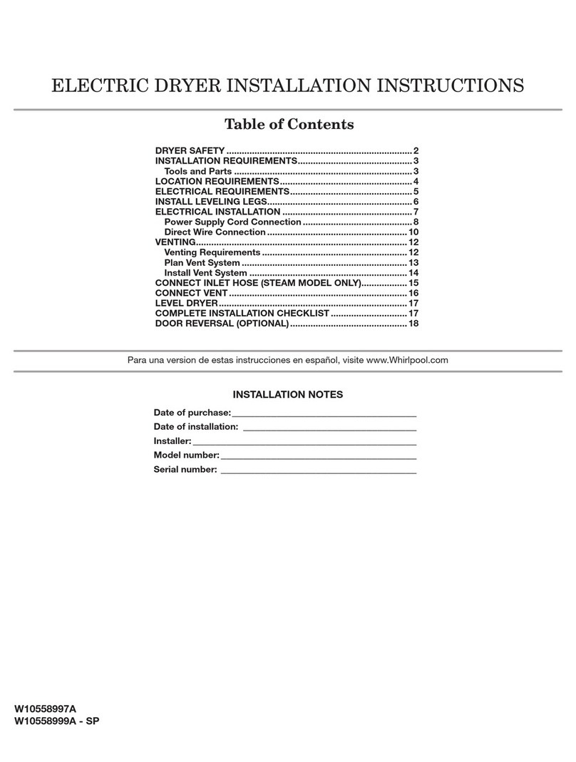
TABLE OF CONTENTS
Whirlpool® and Maytag® Dryer
SECTION 1: GENERAL INFORMATION........................................................................
DRYER SAFETY ..................................................................................................................................
PRODUCT SPECIFICATIONS...............................................................................................................
MODEL AND SERIAL NUMBER LOCATION........................................................................................
MODEL NOMENCLATURE .................................................................................................................
TECH SHEET LOCATION.....................................................................................................................
...............................................
SAFETY ..............................................................................................................................................
SERVICE GUIDE .................................................................................................................................
ACTIVATING SERVICE MODE ............................................................................................................
SERVICE MODE FUNCTION...............................................................................................................
SENSOR FEEDBACK FUNCTION CHART ............................................................................................
SERVICE DIAGNOSTICS CHART.........................................................................................................
FAULTS AND ERROR CODES..............................................................................................................
TROUBLESHOOTING GUIDE .............................................................................................................
...........................................................................
SAFETY ..............................................................................................................................................
......................................................................
TROUBLESHOOTING TESTS...............................................................................................................
TROUBLESHOOTING GUIDE FOR CONNECTED DRYER.....................................................................
STRIP CIRCUITS.................................................................................................................................
WIRING DIAGRAMS..........................................................................................................................
COMPONENT LOCATIONS.................................................................................................................
SECTION 4: COMPONENT ACCESS .............................................................................
REMOVING THE DOOR ASSEMBLY ...................................................................................................
....................................................
........................................................................
REMOVING THE FRONT PANEL AND DOOR SWITCH .......................................................................
REMOVING THE DRUM LIGHT AND MOISTURE SENSOR.................................................................
REMOVING THE BELT, DRUM, AND ROLLERS...................................................................................
REMOVING THE DRIVE MOTOR........................................................................................................
REMOVING THE THERMAL FUSE AND OUTLET THERMISTOR.........................................................
REMOVING THE HEATER, HIGH LIMIT THERMOSTAT, AND THERMAL CUTOFF
................................................................................................................
..........................................................................................
..........................................
......................................................................
