SP Scientific VIRTIS 2K User manual
FREEZE DRYER OPERATOR’S MANUAL
VIRTIS BENCHTOP 2K, 4K AND 6K
FREEZE DRYERS


Rev 007, 10/11 i
© SP Scientific 2011
Copyright © 2011 SP Scientific. All marks herein are used under license.
All brand or product names mentioned may be trademarks or registered trademarks of their respective
companies.
Part Number 414258
Rev 007, 10/11
SP Scientific 815 State Route 208 3538 Main Street
Gardiner, NY 12525 USA Stone Ridge, NY 12484 USA
(800) 431-8232
(845) 255-5000
SP Service (800) 722-7721
SP Service Fax (845) 687-0024
Website http://www.spscientific.com/
This Freeze Dryer Operator’s Manual contains confidential and proprietary information of SP Scientific
and may be used only by a recipient designated by and for purposes specified by SP Scientific.
Reproduction of, dissemination of, modifications to, or the creation of derivative works from this Freeze
Dryer Operator’s Manual, by any means and in any form or manner, is expressly prohibited, except with
the prior written permission of SP Scientific. Permitted copies of this document must retain all proprietary
notices contained in the original.
The information in this document is subject to change without prior notice. Always confirm with SP
Scientific that you are using the most current version of this document. SP Scientific is free to modify any
of its products and services, in any manner and at any time, notwithstanding the information contained in
this document.
THE CONTENTS OF THIS DOCUMENT SHALL NOT CONSTITUTE ANY WARRANTY OF ANY KIND,
EITHER EXPRESSED OR IMPLIED, INCLUDING BUT NOT LIMITED TO THE IMPLIED WARRANTIES
OF MERCHANTABILITY AND/OR FITNESS FOR A PARTICULAR PURPOSE OR GIVE RISE TO ANY
LIABILITY OF SP SCIENTIFIC, ITS AFFILIATES OR ITS SUPPLIERS.
The terms and conditions governing the use of this Freeze Dryer Operator’s Manual shall consist of those
set forth in written agreements with SP Scientific.

ii Rev 007, 10/11
© SP Scientific 2011
Important Symbols
WARNING!
INJURY OR EVEN DEATH
MAY RESULT IF A
RECOMMENDATION
MARKED WITH THIS
SYMBOL IS NOT HEEDED.
CRUSH HAZARD. KEEP HANDS
CLEAR WHEN OPERATING
DOOR.
ELECTRIC SHOCK DANGER!
USE APPROPRIATE
CAUTION TO AVOID INJURY
OR DEATH.
CORROSIVE CHEMICAL. WEAR
SUITABLE GLOVES, SAFETY
GLASSES, AND PROTECTIVE
CLOTHING.
BURN DANGER!
POTENTIALLY HOT
SURFACE. USE
APPROPRIATE CAUTION.
PROPERTY CAUTION! TO
PREVENT DAMAGE TO
CHAMBER EQUIPMENT
AND/OR LOAD, ADHERE TO
PROCEDURES MARKED BY
THIS SYMBOL.
DO NOT STORE
FLAMMABLE MATERIALS IN
CHAMBER.
PRACTICAL OPERATING TIP.
THESE RECOMMENDATIONS
STREAMLINE UNIT OPERATION
AND PREVENT COMMON
OPERATOR ERRORS.
WEAR SAFETY GLASSES. EXPLOSIVE MATERIALS
HAZARD! KEEP OBJECTS
AWAY FROM HEAT.
Freeze Dryer Safety Warnings
Always assume that shelf, condenser and internal parts may be very cold or very hot. Wear protective
equipment to avoid burns.
Always ensure that only an authorized technician services the refrigeration, heat transfer, vacuum and electrical
systems.
Always ensure that refrigeration air intake is clear and clean.
Always ensure vacuum pump exhaust is properly ventilated and/or contained.
Always practice team lifting when moving heavy equipment.
Always use a maximum one pound regulator if backfilling from an inert gas source.
Always wear safety glasses when using glass flasks.
Do carefully read the entire instruction manual before attempting to operate the freeze dryer.
Do verify that the electric service and other utilities match the unit’s requirements before connecting to power.
Never allow hand or body contact with open vacuum ports.
Never clean with solvents. Use mild detergent and water only.
Never operate the unit without all covers in place.
Never pressurize chambers. Laboratory freeze-drying systems are designed for vacuum only.
Never use acrylic closures if they are cracked or crazed.
Never use with toxic, corrosive, flammable or organic materials unless special precautions are in place to
prevent injury to personnel or damage to equipment.

Rev 007, 10/11 iii
© SP Scientific 2011
Warranty Information (VirTis Lyophilizers)
VirTis BenchTop 2K, 4K and 6K Lyophilizers are warranted by SP Scientific to be free of defects in
material and workmanship when operated under normal conditions as specified in the instructions
provided in this manual. Please take this opportunity to locate the serial tag on your new VirTis BenchTop
2K, 4K and 6K and record the information below for future reference. SP Scientific also recommends that
you complete and return your unit’s warranty registration card.
Model Number
Serial Number
Part Number
Limited Warranty
SP Scientific (the “Company”) warrants each of its products against any defects in material or
workmanship, provided that the product is used in a reasonable manner under appropriate conditions and
consistent with the applicable operating instructions, for a period of 12 months from the date of installation
or 15 months from the date of shipment (whichever comes first).
The obligation of the Company shall be, at its option, to repair or replace, without charge any parts that
prove to be defective within the warranty period, if the purchaser notifies the Company promptly in writing
of such defect. The Company shall not be responsible for labor charges payable with respect to persons
other than Company employees. Replacement or repair of parts pursuant to this warranty shall not in any
way extend the original warranty period. The Company will not be responsible for any unauthorized
repairs, replacements or product modifications, nor will it be responsible for any product failures resulting
from such unauthorized repairs, replacements or product modifications negligently or otherwise made by
persons other than Company employees or authorized representatives of the Company.
THE COMPANY DOES NOT MAKE AND EXPRESSLY DISCLAIMS ANY WARRANTY OF
MERCHANTABILITY OR FITNESS FOR A PARTICULAR PURPOSE OR ANY OTHER WARRANTY,
EXPRESSED OR IMPLIED, WITH RESPECT TO THE SALE, INSTALLATION, DESIGN OR USE OF ITS
PRODUCTS. ADDITIONALLY, THE COMPANY SHALL NOT BE LIABLE FOR ANY CONSEQUENTIAL
DAMAGES RESULTING FROM THE USE OF OR ANY DEFECTS IN ITS PRODUCTS.
The Company’s employees are available to provide general advice to customers concerning the use of
the Company’s products; however, oral representations are not warranties with respect to particular
products or their uses and may not be relied upon if they are inconsistent with the relevant product
specifications for the items set forth herein.
Notwithstanding the above, the terms and conditions set forth in the Company’s formal sales contracts
shall be controlling and supersede any inconsistent terms contained herein, and any changes to such
contracts must be made in writing and signed by an authorized executive of the Company.

iv Rev 007, 10/11
© SP Scientific 2011

Rev 007, 10/11 v
© SP Scientific 2011
Contents
Important Symbols ............................................................................................................................................... ii
Freeze Dryer Safety Warnings............................................................................................................................. ii
Warranty Information (VirTis Lyophilizers) .......................................................................................................... iii
Introduction .................................................................................................................1
Features...............................................................................................................................................................1
BenchTop Usage .................................................................................................................................................1
Cold Trap Condenser Module ..............................................................................................................................1
Available Configurations ......................................................................................................................................2
Installation and Startup ............................................................................................... 3
Initial Inspection ...................................................................................................................................................3
Service Connections ............................................................................................................................................3
Vacuum Pump Installation ...................................................................................................................................4
Installing the Vacuum Pump............................................................................................................................4
Oil Mist Eliminators..........................................................................................................................................5
BenchTop Setup ..................................................................................................................................................5
Vacuum Baffle Plate ............................................................................................................................................6
Freeze-Drying Concepts ............................................................................................. 7
Overview..............................................................................................................................................................7
Elements of Freeze-Drying ..................................................................................................................................7
Freeze .............................................................................................................................................................7
Vacuum ...........................................................................................................................................................7
Heat.................................................................................................................................................................8
Condenser.......................................................................................................................................................8
Product Dependencies.........................................................................................................................................8
Sentry 2.0 Controls ..................................................................................................... 9
LED Wave Display (Qualitative Reference) .........................................................................................................9
Button Functions ................................................................................................................................................10
Up/Down (+/-) Buttons...................................................................................................................................10
MENU Button ................................................................................................................................................10
COND Button ................................................................................................................................................10
VAC Button....................................................................................................................................................10
AUTO Button .................................................................................................................................................10
DEFR Button .................................................................................................................................................10
LCD Display Functions ......................................................................................................................................11
Main Menu .........................................................................................................................................................11
Vacuum Control.............................................................................................................................................12
Purge.............................................................................................................................................................12
Bath...............................................................................................................................................................12
Heat (Optional) ..............................................................................................................................................12
User Options Menu ............................................................................................................................................12
Vacuum Control.............................................................................................................................................12

Contents
V
irTis BenchTop 2K, 4K and 6
K
vi Rev 007, 10/11
© SP Scientific 2011
Temperature Units.........................................................................................................................................12
Vacuum Units ................................................................................................................................................13
Relay Test .....................................................................................................................................................13
Vacuum Pump Maintenance .........................................................................................................................13
Alarms Menu......................................................................................................................................................14
Setpoints Menu ..................................................................................................................................................14
Condenser Temperature ...............................................................................................................................14
Vacuum OK ...................................................................................................................................................14
Power Save Deadband .................................................................................................................................14
Maintenance Menu and Factory Options ...........................................................................................................15
Factory Options .............................................................................................................................................15
Interstage Control..........................................................................................................................................16
Calibration .....................................................................................................................................................16
Basic Operation......................................................................................................... 19
Getting Started...................................................................................................................................................19
Product Preparation: Flask/Manifold Drying.......................................................................................................19
Product Preparation: Drum Manifold Shelf Drying .............................................................................................19
Product Preparation: Chamber Drying ...............................................................................................................20
Quickseal Valves ...............................................................................................................................................20
Operation Instructions........................................................................................................................................21
Meltback.............................................................................................................................................................22
Preventing Glassware Breakage........................................................................................................................23
Product Dryness End Point ................................................................................................................................23
Stoppering (Optional) .........................................................................................................................................23
Cold Trap Condenser................................................................................................ 25
Overview............................................................................................................................................................25
Product Requirements .......................................................................................................................................25
Cold Trap Setup.................................................................................................................................................26
Optional Components ............................................................................................... 27
Manifolds............................................................................................................................................................27
Shelf Racks........................................................................................................................................................28
Liquid Nitrogen Trap ..........................................................................................................................................29
Filter Trap...........................................................................................................................................................30
Degassing Filter Trap Cartridges...................................................................................................................30
BenchTop Cold Plate .........................................................................................................................................31
Initial Setup of the BenchTop Cold Plate .......................................................................................................31
Cold Plate Operation .....................................................................................................................................31
General Maintenance................................................................................................ 33
Vacuum System.................................................................................................................................................33
Vacuum Pump...............................................................................................................................................33
Changing Vacuum Pump Oil .........................................................................................................................33
Vacuum Tubing and Gaskets ........................................................................................................................34
Condenser Gasket ........................................................................................................................................34
Vacuum Pump Gas Ballast Valve..................................................................................................................35
Quickseal Valves...........................................................................................................................................36
Refrigeration System .........................................................................................................................................36
The Air-Cooled Condenser............................................................................................................................36
Condenser Chamber .....................................................................................................................................36
Acrylic Parts .......................................................................................................................................................37
Appendix A: Troubleshooting .................................................................................... 39

V
irTis BenchTop 2K, 4K and 6
K
Contents
Rev 007, 10/11 vii
© SP Scientific 2011
Vacuum Problems..............................................................................................................................................39
Product Melting ..................................................................................................................................................40
Appendix B: Serum Vial Capacities........................................................................... 41
Appendix C: Stainless Steel Cleaners....................................................................... 43

Contents
V
irTis BenchTop 2K, 4K and 6
K
viii Rev 007, 10/11
© SP Scientific 2011

Rev 007, 10/11 1
© SP Scientific 2011
Chapter
1
Introduction
VirTis BenchTop 2K, 4K and 6K freeze dryers offer a solution for laboratories with
space constraints. Featuring condenser temperatures of -55 °C to -105 °C, BenchTop
freeze dryers can handle a wide range of processing requirements.
Features
Compact design.
Direct chamber, flask and/or shelf drying capabilities.
Versatile Sentry 2.0 control panel with digital display of temperatures and
setpoints.
Three- to nine-liter condenser capacity.
Variety of refrigeration system options.
Quickseal valves for processing flasks.1
Manual shelf stoppering (optional).
BenchTop Usage
BenchTop units are mechanically refrigerated condenser modules that can be utilized
as both freeze dryers and cold traps. These units can also be used for initial product
freezing. When used in freeze-drying mode, a BenchTop unit can effectively remove
up to 99% of product moisture.
Cold Trap Condenser Module
When using a vacuum concentrator or gel dryer with your BenchTop unit, the
condenser module can be used as a cold trap, trapping vapors driven off the product
before they reach the vacuum pump. To configure the BenchTop for cold trap
application, replace the condenser cover plate or adapter plate with a cold trap
adapter plate with a ¾-inch stainless steel port. For more information, refer to Chapter
6: Cold Trap Condenser.
Note: A low temperature condenser is required when trying to trap organic solvents.
1Requires optional manifold.
Introduction
V
irTis BenchTop 2K, 4K and 6
K
2 Rev 007, 10/11
© SP Scientific 2011
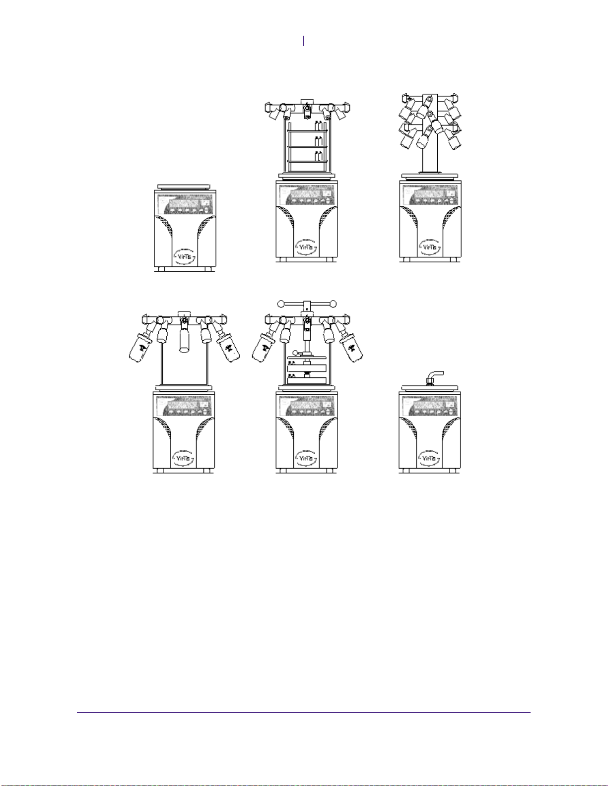
Available Configurations
Freeze-drying in
the condenser Shelf unit in
drum manifold Vertical manifold
Flask drying on
drum manifold Flask drying on drum
manifold with stoppered
shelves
Fitted for cold
trap application

Rev 007, 10/11 3
© SP Scientific 2011
Chapter
2
Installation and Startup
Initial Inspection
Inspect the contents of your shipment immediately upon arrival. Check packing
material for possible small accessory items. DO NOT ACCEPT damaged shipments
from a carrier without a signed notification of damages.
If concealed damage and/or loss is discovered, contact the freight carrier immediately.
Keep the contents, packing material and related paperwork intact until the written
report is obtained.
If your shipment is “FOB Destination” file your claim with SP Scientific and
include the inspection report and any other supporting documents.
If your shipment is “FOB Shipping Point” file your claim with the freight carrier
and include the inspection report and any other supporting documents.
Note: SP Scientific will cooperate in the matter of collecting your claim, but is not responsible
for the collection or free replacement of the material. When possible, replacement parts will be
shipped and invoiced to you, making them a part of your claim.
Service Connections
Make sure that the outlet you intend to use meets the voltage and amperage
requirements listed on the serial tag of your unit.
CAUTION! ONLY A QUALIFIED ELECTRICIAN SHOULD CONNECT THE UNIT TO
THE AVAILABLE ELECTRICAL SUPPLY.
The line cord has three individual conductors inside the outer jacket.2To make the
appropriate plug connection:
1. Trim back enough of the jacket to facilitate installation of the plug.
2. The three individual conductors are BROWN, BLUE, and GREEN with a
YELLOW tracer.
3. Connect the BROWN wire to the line (hot) terminal on the plug.
4. Connect the BLUE wire to the neutral terminal.
5. Connect the GREEN/YELLOW wire to the ground terminal.
2Consult SP Scientific and a qualified electrician if electrical configurations vary from standard, specified service requirements.

Installation and Startup
V
irTis BenchTop 2K, 4K and 6
K
4 Rev 007, 10/11
© SP Scientific 2011
Vacuum Pump Installation
A remotely mounted vacuum pump is required for the operation of your BenchTop
freeze dryer. The vacuum pump must be a two-stage, high-vacuum pump that does
not exceed the maximum allowable amperage listed on the unit’s serial tag and back
panel label.
The following parts are included with your BenchTop unit for connection to the
vacuum pump:
Four (4) feet of ¾-inch ID (Inside Diameter) rubber vacuum tubing.
One (1) 90° rubber elbow
One (1) plastic connector
Installing the Vacuum Pump
Notes: If you are installing a previously used vacuum pump, refer to the vacuum pump manual
and the General Maintenance section of this manual. Ensure that the pump was properly
maintained prior to installation.
A vacuum pump inlet port adapter and sufficient tubing are required for connection to the
vacuum pump. If you need assistance, please contact SP Scientific.
1. Position the vacuum pump in a convenient location
near the freeze dryer. Ensure that the pump will be
easily accessible during routine maintenance.
2. Cut the supplied vacuum tubing as short as possible.
Allow enough length between the vacuum pump and
the BenchTop unit.
Note: Clamp and cut the ¾-inch ID vacuum hose. If you do
not wish to cut the hose, it may be used at its full length,
but might take up more space than necessary.
3. Locate the inlet port on your vacuum pump. Refer to
the vacuum pump manual.
4. Remove any material with the exception of the inlet
filter screen and gasket.
5. Place the adapter on the inlet port and secure with a
fitting. If an adapter is not present, contact SP
Scientific.
6. Remove all objects from the vacuum pump outlet
port, but retain for future use.
7. Connect the BenchTop unit to the vacuum pump
using the ¾-inch vacuum tubing. If connecting to a
vacuum pump purchased from SP Scientific, attach
the ¾-inch tubing from the BenchTop to the vacuum
pump intake nipple, add a tubing clamp and tighten
securely.
8. Check the vacuum pump oil level. The oil level should read half way up the
sight glass. Add oil only if necessary. DO NOT OVERFILL!
Note: Refer to your vacuum pump manual for more information.
Vacuum pump

V
irTis BenchTop 2K, 4K and 6
K
Installation and Startup
Rev 007, 10/11 5
© SP Scientific 2011
9. Verify that the power switch on the vacuum is off. The LED next to the VAC
button on the unit’s front panel must be off.
10. Plug the vacuum pump into the receptacle marked VACUUM PUMP on the
back of the unit. The receptacle is an IEC universal outlet. This allows you to
control the pump using the Sentry 2.0 controller. The voltage, phase and
frequency of the vacuum pump must match the voltage, phase and frequency
specified on the rear panel of the freeze dryer.
Note: You can power your vacuum pump from a wall socket if it does not have an IEC
connector, but you will not be able to control the pump from the Sentry 2.0 Controller.
Only a qualified electrician should perform installation of an IEC connector. The pump
used should not exceed the amperage listed on the BenchTop serial tag.
11. Enable power to the vacuum pump by switching the pump’s circuit breaker to
the on position.
Oil Mist Eliminators
To reduce fumes from the vacuum pump and/or vent the vacuum exhaust externally,
SP Scientific recommends the installation of an Oil Mist Eliminator (OME).
BenchTop Setup
To set up your BenchTop unit:
Note: Refer to Chapter 5: Basic Operation for complete equipment operation instructions.
1. Install the condenser gasket (black rubber ring with a slit in it) on the top of
the unit. It should have a light film of vacuum grease on the outer surface.
2. Prepare the unit for your intended use.
a. If the unit is to be used as a standalone freezer, cover the condenser
with a plain cover plate to prevent air circulation from warming the
samples. Skip to step 5.
b. If the unit is to be used as a manifold dryer, place a manifold adapter
plate (clear acrylic or stainless steel circular disk with a hole) over the
gasket.
c. If you are using an acrylic drum manifold, place a second condenser
gasket around the bottom lip of the manifold.
d. If you are using a stainless steel manifold, place the supplied O-ring
in the groove of the manifold adapter plate.

Installation and Startup
V
irTis BenchTop 2K, 4K and 6
K
6 Rev 007, 10/11
© SP Scientific 2011
BenchTop with acrylic manifold.
3. If using a manifold, attach Quickseal valves to each port on the manifold and
ensure that each is in the closed position. For more information, refer to the
Quickseal valve section in Chapter 5.
Note: Quickseal valves are siliconized at the factory. Vacuum grease is not required.
4. If using an acrylic drum manifold, apply a thin coating of vacuum grease to the
tapered surface and place the tapered plug in the top center of the manifold.
Slowly turn the plug 360° clockwise and then 360° counterclockwise. This will
ensure a good seal between the surface of the plug and the manifold.
5. Plug the unit into an appropriate outlet and switch on the circuit breaker
located on the rear of the unit. The control panel display will illuminate.
Vacuum Baffle Plate
The BenchTop 2K and 4K models include a two-position vacuum baffle plate.
Baffle Plate on Chamber Bottom (Position 1).
By raising the baffle plate handle, the plate can be
dropped to the bottom of the chamber. This allows you
to pre-freeze items on the baffle plate. In some cases, it
may be more convenient to remove the baffle plate
completely and freeze items directly on the bottom of
the chamber.
Note: Freeze-drying cannot be performed with the baffle on the chamber bottom
(position1) as the product will remain too cold for water vapor transfer.
Baffle Plate in Raised Position (Position 2).
Lower the baffle plate handle to raise the baffle plate
when freeze-drying products directly on the baffle.
This allows ice to build up on the condenser below
and provides more room for the materials to be dried.

Rev 007, 10/11 7
© SP Scientific 2011
Chapter
3
Freeze-Drying Concepts
Overview
During the first phase of lyophilization (freeze-drying), the product is typically frozen to
a temperature below its eutectic point (i.e., at least -40 °C). After the product is frozen,
moisture is extracted through a process called sublimation. The sublimation process
takes a solid (i.e., ice) and converts it to a gas (i.e., vapor), bypassing the liquid stage.
The moisture is converted to a gas, while maintaining the material’s crystalline
structure.
The second step involves the migration of moisture from the product. This migration of
moisture is facilitated by using a vacuum to extract the non-condensable vapors in the
chamber. The freeze dryer creates a pressure-free zone to allow moisture to flow
easily from the product. Since vapor naturally travels toward cooler surfaces, the
condenser chamber must be cooled to at least 15 °C below that of the product to
attract product moisture.
Many products require a secondary drying process to remove moisture that did not
convert to vapor during the first process. During secondary drying, BenchTop units
remove the remaining bound moisture by slightly warming the product.
Note: To prevent meltback, the product should not be warmed above its eutectic temperature
until all free ice has sublimated.
Elements of Freeze-Drying
VirTis-brand freeze dryers create the optimal environment for sublimation to occur by
combining the four elements of freeze-drying:
Freeze
The product must be completely frozen before freeze-drying can begin. Product
freezing can be accomplished directly in the 2K and 4K condenser chamber. The
product’s frozen temperature should be at least -40 °C. To minimize freeze-drying
time and protect the product against meltback, the product should be frozen in the
thinnest cross section possible.
Vacuum
Adding vacuum assists in removing air and other non-condensable vapors from the
chamber to facilitate vapor migration. The vacuum system creates a nearly pressure-
free environment to allow the vapor from the frozen product to flow toward the cold
condenser surface easily.

Freeze-Drying Concepts
V
irTis BenchTop 2K, 4K and 6
K
8 Rev 007, 10/11
© SP Scientific 2011
Heat
Adding heat to the frozen product speeds the drying process. The BenchTop unit is
designed to be used as either a manifold freeze dryer or a tray dryer. Exposing
glassware containing frozen product to ambient room temperature helps drive the
drying process by adding heat. This causes the frozen solvents in the product to
sublimate and then migrate to the colder surface of the condenser wall.
Several heated and unheated racks and stoppering accessories are available for
freeze-drying in drum manifolds.
In its simplest configuration, a BenchTop unit will freeze-dry products on the partially
raised vacuum baffle in the center of the condenser. Heat will be added by radiation
through the acrylic cover.
Condenser
Trapping water vapor molecules in the form of ice on the condenser surface
effectively removes moisture from the product. The refrigeration system cools the
internal condenser at the bottom of the chamber to attract and trap vapors migrating
off the product.
The condenser is located under the manifold to provide the shortest vapor path to
achieve the maximum drying rate. The condenser capacity ranges from 3 to 9 liters,
which indicates the maximum volume that can be condensed from the product before
defrosting is necessary.
Product Dependencies
The freeze-drying process is completely dependent upon, and will therefore change
with, each specific product. In all cases, the condenser temperature must be cold
enough to trap the vapors migrating from the product effectively. If the condenser is
not cold enough, excess vapors may be pulled into the vacuum pump inadvertently.
To compensate for this issue, SP Scientific offers optional filter and liquid nitrogen
(N2(liq)) traps.

Rev 007, 10/11 9
© SP Scientific 2011
Chapter
4
Sentry 2.0 Controls
The Sentry 2.0 is the control center for the BenchTop K series. Driven by a powerful
microprocessor, the Sentry 2.0 provides extreme versatility while remaining intuitively
easy to use. The controller allows for custom programming, includes a detailed LCD
display and offers flexibility with a wealth of configurable features.
The Sentry 2.0 front panel consists of the following:
An LED wave display, which allows you to assess the status of the system
quickly and easily.
Tactile buttons located on the membrane, which allow you to activate specific
functions and navigate through the menus within the LCD display.
An LCD display, which shows the status of the unit and allows you to adjust
the alarm and control parameters, as well as modify system configurations.
LED Wave Display (Qualitative Reference)
1. Condenser Temperature
The LEDs on the bottom wave represent the following temperatures:
LED Temperature (°C) Color
1 10 Red
2 0 Red
3 -10 Red
4 -20 Amber
5 -30 Amber
6 -40 Green
7 ≤-50 Green

Sentry 2.0 Controls
V
irTis BenchTop 2K, 4K and 6
K
10 Rev 007, 10/11
© SP Scientific 2011
2. Vacuum
The LEDs on the top wave represent the following vacuum setpoints:
LED Vacuum (mT) Color
1 2000 Red
2 1000 Red
3 500 Amber
4 200 Amber
5 100 Green
6 50 Green
7 ≤20 Green
Button Functions
Up/Down (+/-) Buttons
The Up/Down (+/-) buttons allow you to navigate the menus and increase or decrease
setpoint values displayed on the LCD display.
MENU Button
The MENU button performs a number of functions. During an alarm condition,
pressing MENU will temporarily silence (but not clear) the alarm. When viewing the
Synoptic screen, the MENU button will display the Main Menu.
The MENU button also acts as an enter key, activating the selected option. To return
to a previous menu, highlight the carat (^) at the top left corner of the LCD screen and
press the MENU button.
COND Button
The COND button activates the refrigeration system. This provides system cooling for
vapor condensing.
VAC Button
The VAC button enables the vacuum pump and opens the vacuum brake solenoid
(VBS) valve, allowing the system to be evacuated. Vacuum level control options can
be programmed from the User Options screen.
Note: If your vacuum pump is not connected to the IEC plug on the rear of the BenchTop unit,
the VAC button will not control your pump. See your pump manual for operation instructions.
AUTO Button
The AUTO button will start the refrigeration and vacuum systems in a set sequence.
The condenser will first cool to the condenser setpoint. Once the setpoint is achieved,
the vacuum pump will energize and begin evacuating the system.
DEFR Button
The DEFR button activates the condenser defrost function. Hot gas defrost is directed
toward the condenser walls to quickly loosen ice.
Note: Defrost mode is disabled while any other function is on.
This manual suits for next models
2
Table of contents
Other SP Scientific Dryer manuals


Popular Dryer manuals by other brands


Drieaz
Drieaz Ace TurboDryer owner's manual

Hotpoint
Hotpoint TVFM 60C Futura Instruction booklet

Miele
Miele Touchtronic T 8019 C Operating and installation instructions

LG
LG DLE2601R specification

Hoover
Hoover VTC 680C Instruction book

American Dryer Corp.
American Dryer Corp. Heat Reclaimer AD-170HR parts manual


