Shini SHD Series User manual

SHD
Standard”HopperDryer
Date: Dec, 2018
Version:Ver.E


3(28)
Content
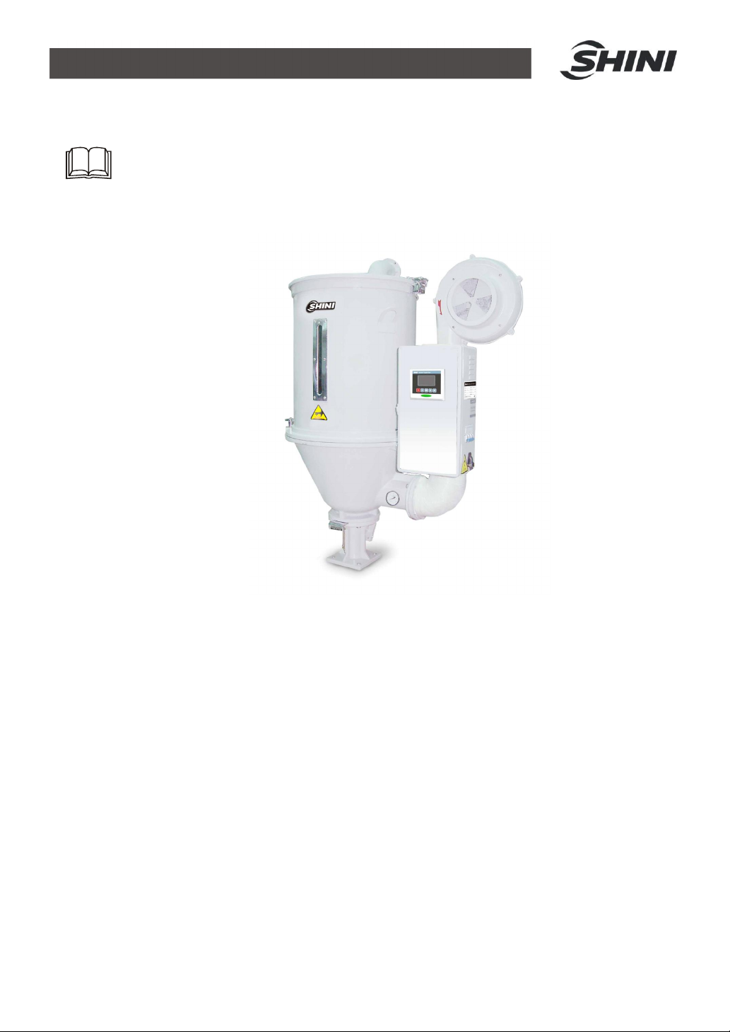
1. General Description..................................................................................... 5
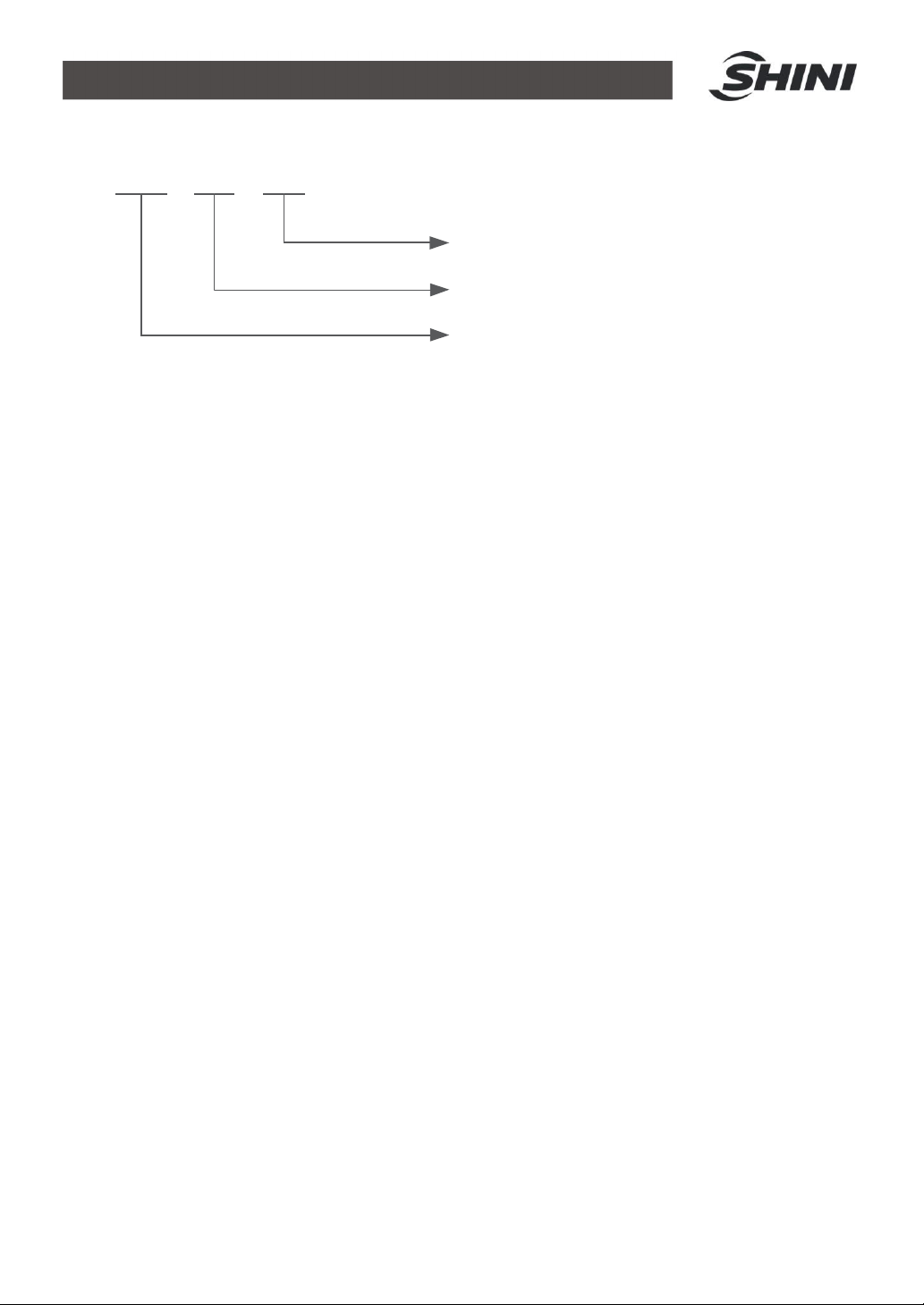
1.1 CodingPrinciple......................................................................................6
1.2 Feature....................................................................................................6
1.3 TechnicalSpecifications..........................................................................8
1.3.1 ExternalDimensions......................................................................8
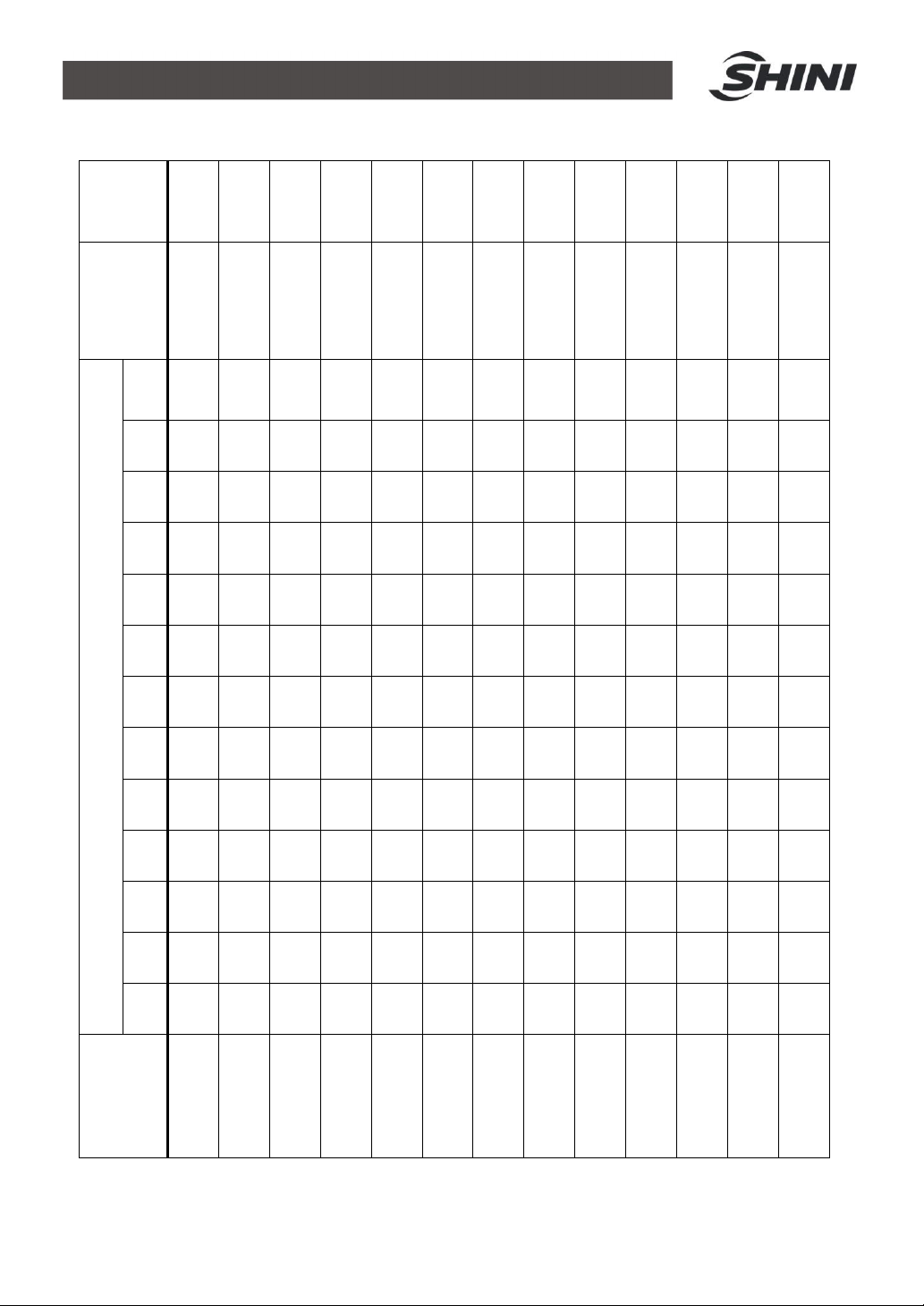
1.3.2 Specification..................................................................................9
1.4 SafetyRegulations................................................................................ 11
1.4.1 SafetySignsand Labels.............................................................. 11
1.4.2 Signsand Labels......................................................................... 12
1.5 ExemptionClause................................................................................. 12
2. StructureCharacteristics and WorkingPrinciple.................................... 13
2.1 WorkingPrinciple.................................................................................. 13
2.2 Options.................................................................................................. 14
2.2.1 Air Filter....................................................................................... 14
2.2.2 BlowerInlet Filter......................................................................... 14
2.2.3 MagneticBase............................................................................. 14
2.2.4 Hot Air Recycler........................................................................... 15
2.2.5 HopperMagnet............................................................................ 15
2.2.6 MaterialSuction Box/Shut-off Suction Box.................................. 16
2.2.7 N-Type FloorStand..................................................................... 16
3. Installation and Debugging........................................................................ 17
3.1 Direct Installation................................................................................... 17
3.2 FloorStand Installation......................................................................... 18
3.3 Connectingthe PowerSource.............................................................. 18
3.4 TheHopperDryerTest......................................................................... 18
3.5 Installation of the Options...................................................................... 19
3.5.1 Installation of Air-Exhaust Filter................................................... 19
3.5.2 SuctionBoxInstallation............................................................... 19
3.5.3 BlowerInlet FilterInstallation....................................................... 20
3.5.4 Hot Air RecyclerInstallation......................................................... 20
4. Operation Guide......................................................................................... 22

4(28)
4.1 ControlPanel........................................................................................ 22
4.1.1 PanelOperation........................................................................... 22
4.1.2 TemperatureSetting.................................................................... 22
4.1.3 TemperatureLock....................................................................... 22
4.1.4 PIDSetting.................................................................................. 23
4.1.5 Intermittent OperationSetting...................................................... 24
4.1.6 One-weekTimingSetting............................................................ 24
4.1.7 Communication Setting (optionalfunctions)................................ 24
4.1.8 OperationFlow............................................................................ 26
4.1.9 WrongCodesRemark................................................................. 27
5. Maintenance and Repair............................................................................ 28
5.1 Blower................................................................................................... 28
6. Troubleshooting ......................................................................................... 28
TableIndex
Table1-1: Specification...................................................................................... 9
Table1-2: Dryerdryingcapacity(kg/hr)(Selection guide).................................. 10
PictureIndex
Picture1-1: Externaldimensions........................................................................ 8
Picture2-1:Workingprinciple........................................................................... 13
Picture3-1: Direct installation........................................................................... 17
Picture3-2: Floorstandinstallation................................................................... 18
Picture3-3: Blower........................................................................................... 19
Picture3-4: Left: Air-exhaustelbowofdryer Right: Air-exhaustfilter............. 19
Picture3-5: European suction box.................................................................... 19
Picture3-6: Shut-off suction box....................................................................... 20
Picture3-7: AIFblowerinletfilter...................................................................... 20
Picture3-8: Hotair recycler.............................................................................. 21
Picture4-1: ControlPanel................................................................................. 22

5(28)
1. General Description
Pleaseread throughthisoperation manualbeforeusingthe machine to
prevent damagesofthemachineorpersonalinjuries.
SHD-50

6(28)
1.1CodingPrinciple
Hopper Capacity(kg)
"Standard"Hopper Dryer
Option
S
HD -
xxx -
xxx
1.2Feature
lAdopt hot air diffusertogainaneven hotair flowtoimprovedrying
efficiency.
lHot air inletelbowdesigncan preventdust pilingup atbottomof thepipe
heaterssoastoavoidburning.
lAll materialcontact surfacesaremadeof stainless steeltoeliminate
materialcontamination.
lHopperseparatedfromitsbase,ensuringconvenient cleaning.
lAll seriesareequipped withexposed powerswitch.
lForSHD-25~150,heaterpipesareconnected byaluminumsheetsand
othermodelsareequipped withtemperatureprotectiontoprevent heater
pipe fromdamagingbyblowerfaults.
lOverheat trippingcanautomaticallycut offpowerwhen drying
temperatureexceedsset deviation value.
lAdoptsheat-insulatedblowertoprolongblowerlifespan.
lAll seriesofmodelsstandardequipped with7-daytimingandintermittent
operation function.
lAll seriesofmodelsadoptmicrocomputercontrolandRS485
communicationport.

7(28)
All serviceworkshouldbe carried outbyaperson withtechnicaltrainingor
correspondingprofessionalexperience. The manualcontainsinstructionsforboth
handlingandservicing.Chapter5,whichcontainsserviceinstructionsintendedfor
serviceengineers. Otherchapterscontaininstructionsforthedailyoperator.
Anymodificationsofthe machine mustbeapproved bySHINIinordertoavoid
personalinjuryand damagetomachine.Weshall notbe liableforanydamage
causedbyunauthorized changeof themachine.
Ourcompanyprovidesexcellentafter-salesservice.Shouldyou haveany
problemduringusingthe machine,pleasecontactthecompanyorthe local
vendor.
Headquarterand Taipeifactory
Tel:(886)226809119
ShiniPlastics Technologies(Dongguan), Inc
Tel:(86)769 81116600
ShiniPlastics TechnologiesIndiaPvt.Ltd.
Tel:(91)250 3021166

8(28)
1.3Technical Specifications
1.3.1ExternalDimensions
SHD-12 SHD-25~150
SHD-200~600 SHD-800/1000
Picture1-1: Externaldimensions

9(28)
1.3.2Specification
Table1-1: Specification
SHD- 12 25 50 75 100 150
200
300
400
500
600
800
1000
Ver. D C C C C C D D E D D D D
HeaterPower
(kW)
2.2
/3*
3
/3.3*
3.9
/4.2*
4.2
/4.8*
6
/6.6*
6.6
/7.2*
8.4
/9.6*
9.6 18 19.2
21 24 32
Blower Power
(kW)
0.05
0.12
0.12
0.12
0.12
0.12
0.18
0.18
0.55
0.55
0.55
1.1
1.1
Loading
Capacity(kg)
12 25 50 75 100 150
200
300
400
500
600
800
1000
H(mm) 790
1015
1145
1240
1340
1620
1580
1980
2170
2350
2570
2760
3060
H1(mm) 690
925
1045
1150
1340
1605
1332
1432
1900
1900
2075
2300
2530
H2(mm) 317
410
380
475 470 470
550
550
838
838
838
1010
1010
H3(mm) 370
460
520
620 725 970
975
1220
1220
1400
1545
540
540
H4(mm) 106
194
206
208 233 233
184
184
334
334
334
1550
1845
H5(mm) 115
150
150
150 158 158
158
158
283
283
283
283
283
W(mm) 660
725
840
900 955 955
1230
1230
1365
1365
1365
1420
1420
D(mm) 360
405
490
550 605 605
770
770
915
915
950
600
600
D1(mm) 130
158
158
158 238 238
238
238
345
345
345
345
345
W1(mm) 130
148
148
148 238 238
238
238
345
345
345
345
345
A(mm) 325
385
470
530 595 595
750
750
910
910
910
960
960
B(mm) 55 55 55 55 90 90 90 90 105
105
105
105
105
Weight (kg) 35 40 45 55 70 75 100
120
165
170
240
280
300
Note: 1)Aboveloadingcapacityisbasedonpelletmaterialof 0.65kg/Linbulkdensityand3~5mm indiameter.
2) “*”Standsforhigh-temp.model,add"H" attheendof model code.
3) MaximumdryingtemperatureofSHD-EHis 150°C.
4) Power: 3 ,230/400/460/575VAC,50/60Hz.

10(28)
Table1-2: Dryerdryingcapacity(kg/hr)(Selection guide)
Drying
Temp.
80
80
80
80
80
75
75
75
80
75
-
120
70
Drying Time
0.75hrs
0.75hrs
0.75hrs
1hrs
1hrs
4hrs
5hrs
7hrs
2.5hrs
2.25hrs
1.5hrs
3hrs
1.25hrs
ModelSHD
1000
1000
1000
1000
750
400
200
165
110
330
375
430
200
510
800
800
800
800
600
320
160
130
90
365
300
380
160
445
600
600
600
600
440
240
120
100
70
200
220
330
120
380
500
500
500
500
375
200
100
80
60
165
180
275
105
305
400
400
400
400
300
160
80
65
50
140
150
220
90
250
300
300
300
300
225
120
60
45
35
100
110
160
75
185
200
200
200
200
150
80
35
30
20
60
70
100
40
120
150
150
150
150
115
60
27
22
15
45
52
75
30
90
100
100
100
100
80
40
20
16
10
30
35
50
20
60
75
75
75
75
57
30
13
11
7
22
26
37
15
45
50
50
50
50
38
20
10
8
5
12
17
25
10
30
25
20
20
20
14
8
4
3.2
2
6
6
10
4
12
12
8
8
8
6
4
2
1.5
1
2.5
2.5
4
1.5
5
Material
Polystyre
Polyethylen
Poly propyrene
Poly styrence
H
·
D
ABS
Nylon11,12
Nylon6/6,6/10
Nylon6
Acrylicfiber
Cellulose
acetate
Butyrate
Polycarbonate
RigidPVC
Notes:Basedonrelativehumidity65%withambienttemperatureof20 ,moisurecontentafterdryingcanbe
0.2% roless.

11(28)
1.4SafetyRegulations
1.4.1SafetySignsand Labels
Note!
Electricalinstallationshouldbe done byqualifiedelectrician only.
BeforeconnectingtoACPowerSource,turnpowerswitchtoOFF position.
WhileACpowersourceisconnected,makesurespecificationsand
overload protectionratingofthepowerswitcharesuitableandreliable.
When themachineisundercareormaintenance,turnoffbothpower
switchand automaticoperationswitch.
Danger!
Highpresscure!
It isattachedtothecontrolbox.
Warning!
Hightemperaturesurfacemayburnhands!
It isattachedonthecoverofpipe heater.
Attention!
Thismarkremindsyoutobemorecareful!
Warning!
Hightemperaturesurfacemayburnhands!
Thislabelshouldbestick tothe shell of electricheatingbox.

12(28)
1.4.2Signsand Labels
Protectiondeviceactivateswhen overheat
occurs;afterfaultsaredischarged,press
blue keytoresetandturnontheswitchto
Restart operation.
Push-and-pull switchforshut-off plate:
I: Means"Pull"
O: Means"Push"
Regularlyclean the filterscreen toavoid
insufficient dryingcaused byblocking
Communication interfaceRS485
1.5 Exemption Clause
Thefollowingstatementsclarifythe responsibilitiesandregulationsbornbyany
buyeroruserwho purchasesproductsandaccessoriesfromShini(including
employeesandagents).
Shiniisexemptedfromliabilityforanycosts,fees,claimsandlossescausedby
reasonsbelow:
1.Anycareless orman-madeinstallations, operation and maintenances
uponmachineswithoutreferringtotheManualpriortomachine using.
2.Anyincidentsbeyondhuman reasonablecontrols, whichinclude
man-made viciousordeliberatedamagesorabnormalpower, and
machine faultscaused byirresistiblenaturaldisastersincludingfire,flood,
stormandearthquake.
3.Anyoperationalactionsthatarenotauthorized byShiniuponmachine,
includingaddingorreplacingaccessories,dismantling, deliveringor
repairing.
4.Employingconsumablesoroil mediathatarenotappointed byShini.

13(28)
2. Structure Characteristics andWorkingPrinciple
2.1 WorkingPrinciple
Picture2-1:Workingprinciple
Inthedryingprocess,hotair withconstanttemperatureisblownbythe drying
blower2ofSHD intothe dryinghopper7todrythe materials.Moisturewill be
separatedout and takenawaybyhot air, thustogainasatisfieddryingeffect.
Air blownout ofblowerviahot air pipe 4becamehightemperaturedryingair after
beingheated.Through shade separator5andscreen protector6,hotair can be
equablydispersed tothe materialinstoragetank(seepicture).Hotair recycleris
optionalsotheair entered dryinghopper7afterbeingfilteredbyreturnair will get
intothe dryingblower2toform aclosed loopcircle, whichsaveselectricity.

14(28)
2.2Options
2.2.1Air Filter
Effectivelyfilter99%ofdust-containair discharged fromdryertoavoidair
pollution.
2.2.2BlowerInlet Filter
Notes: refill air inputofthe blowerisadjustable.
2.2.3MagneticBase
Made ofaluminumwithbuilt-inhoppermagnet, caneffectivelyseparatemetal
scrapsout toavoidmaterialcontamination. (MB-400 isstandardconfiguration)
Model Applied to
ADC-1 SHD-12
ADC-2 SHD-25~150
ADC-3 SHD-200~1000
Model Applied to
AIF-12 SHD-12
AIF-25 SHD-25
AIF-50 SHD-50/75
AIF-100 SHD-100/150
AIF-200 SHD-200~500
AIF-600 SHD-600
AIF-800 SHD-800~1000
ModelApplied to Magnetic
Frame Aluminum Holder×2
MB-12 SHD-12
MR-3
88.5 ×78 ×2.3
MB-50 SHD-25~75
MB-100
SHD-100~300 118.5 ×105 ×2.3
MB-400
SHD-400 andabove 147 ×130 ×2.3

15(28)
2.2.4Hot Air Recycler
Workwithhopperdryertomakethehotair formasemi-closedcirculatedloop
and hasfeaturesasfollows
1)Hot air recyclingand circulatingavoidsindoortemperaturerisingup.
2)Keepair infactorycleanandensuregood product quality.
3)Heatingbyfasthotair circulation canlowerenergyconsumption by40%.
2.2.5HopperMagnet
ModelApplied to Aluminum Holder×2(mm)
MR-5 SHD-12 (148 x80 x2.3)
MR-7 SHD-25~75 (190 x80 x2.3)
MR-9 SHD-100~400 (240 x80 x2.3)
MR-11 SHD-600 andabove (298 x80 x2.3)
Model
Filtering
Barrel
Dia. (mm)
Inlet Air
Pipe Dia.
(inch)
Flange of
AirOutlet
(inch)
Applied to
HAR-12 157 2 SHD-12
HAR-25 157 2.5 SHD-15
HAR-50 175 3 SHD-50/75
HAR-100
217 3 SHD-100/150
HAR-200
245 4 SHD-200~500
HAR-600
245 4 SHD-600
HAR-800
245 4 SHD-800~1000
Absorbmetalscrapsinthe materialto
avoidthe damageofmoldingscrew.

16(28)
2.2.6MaterialSuction Box/Shut-off Suction Box
Europeanstyleinappearancedesign, workwithdryerthathasafloorstandand
vacuumloader, suitableformaterialsuctionand discharging.
Applied to
Model
SHD-12~75 SHD-100 and above
SBU -20-38S -160-38S
SBU -20-50S -160-50S
SBU -20-38D -160-38D
SBU -20-50D -160-50D
Notes:1) Install pneumatic shut off valve(add "V "at the endofthemodelcode).
2) Changeintostainless steel material (add "S"at theendofthe modelcode).
3) Stainless steel polishing (add"P"at theendofthe model code).
4) “S”standsforsingletubesuctionboxand “D”standsfor doubletubessuctionbox.
2.2.7N-Type FloorStand
Model Applied to Dimension(mm)H×W×D A / B / C (mm)
FSN-50 SHD-12~75 600 ×700 ×640 140/54/ 9
FSN-100 SHD-100/150 615 ×800 ×710 210/90/11
FSN-200 SHD-200/300 680 ×1000 ×840 210/90/11
FSN-400 SHD-400~600 700 ×1200 ×1010 260/116 /13
FSN-800 SHD-800/1000 700 ×1600 ×1180 260/116/13
Withwhichmachinescan be easilymoved outofworkplacewhichissuitablefor
the factorieswithheightlimitedworkshops,alsoitcanmakeoperationsmore
convenient.

17(28)
3. InstallationandDebugging
NotesforInstallationand Positioning
1)Machine just canbemounted inverticalposition. Makesurethere’sno
pipe,fixed structureorotherobjectsabovetheinstallinglocation and
aroundthemachine whichmayblock machine’sinstallation,hit objectsor
injurehumanperson.
2)Inordertomaintainconvenient operation,it’ssuggested tokeep1m
spacearoundthemachine.Pleasekeepatleast 2mdistancebetween the
deviceand theinflammablegoods.
3)Thisseriesof modelsonlycouldbeappliedinworkingenvironmentwith
good ventilation.
3.1Direct Installation
Picture3-1: Direct installation
Directinstallationtype istomountthe hopperdryerdirectlyon the molding
machine viaastandardbase.SHD-12~300issuitableforthismountingmethod
aswell asfloorstandinstallation type;SHD-400 and modelsaboveshouldadopt
floorstandinstallationtype.
When usingthemethod tomountthe dryer,the equippedstandardbasemust
accordingtomaterialinletdiameterofthe moldingmachinemountingdrill holes.
Then usethe screwtofastenthebaseandthemoldingmachineinlet.

18(28)
3.2Floor StandInstallation
Picture3-2: Floorstandinstallation
Floorstand installationtype istomountdryeron afloorstand,thenviaa
photo-sensorhopperreceivertoconveythe materialtothefeed portofamolding
machine.SHD-400 andabovemodelsshouldadopt floorstand installation type.
Machineshouldbeplacedonwater-levelfloortokeepbalance.If itistobe
mountedonahighsurface(e.g.on ascaffoldorainterlayer),shouldensureits
structureandsizescan beartheweight and sizeofthe machine.
3.3Connectingthe Power Source
Accordingtocircuitdiagramofeachmachine toconnectthe powersource.Notice
shouldbe takenconcerningifthepowervoltageisincompliancewiththe required
specifications, alsoifthe switchandloadareproperandsafe.
Notes: Beforeconnecting, the mainswitchshouldbe off.
3.4The Hopper DryerTest
Afterensuringall the circuitshavebeenconnected firmly,turnon themainswitch
to"ON"statusandpressingthe "RUN/STOP"button on controlpanel.Then blower
runs,observewhetherthe rotatingderection oftheblowerissameasthearrow
indicateddirection.Ifitisnot, randomlyexchangetwoofthethreepowerfiring
linesandconnect themfirmly.

19(28)
Picture3-3: Blower
3.5InstallationoftheOptions
3.5.1Installation of Air-Exhaust Filter
If thematerialscontaindustortoavoidthedust-containair exhaustedbydryer
pollutingtheworkshop’senvironment.Option withair-exhaustfilterADC can filter
the exhaustedair fromthe dryer.ADC can reachfilterefficiencyof99%.
ADC isinstalled on air-exhaustelbowofthedryer.Pointittotheinstalled holes
thentightenup thescrews, userubberringtosealthe combinedplace.
Picture3-4: Left: Air-exhaustelbowofdryer Right: Air-exhaustfilter
3.5.2SuctionBoxInstallation
Picture3-5: European suction box

20(28)
When SHD ismountedon thefloorstandsuction boxshouldbeequipped.To
conveythe dried plasticmaterialconveniently.The installation ofsuction boxis
simple.Installthematbottomofthehopper,pointtotheholesandtighten upthe
screws.
Picture3-6: Shut-offsuction box
3.5.3BlowerInlet FilterInstallation
When dryersinthedust-containenvironmentorhotair requireshighcleanliness,
it can optionwithAIFblowerinlet filter.
Picture3-7: AIFblowerinletfilter
InstallingAIFatblowerinletportwhen installingit, firstlyloosen screwsofthe
blowerinletscreen ,takedownthe screen;then install the AIFatblowerinlet
port, pointtothe holesand tighten up the screws.
3.5.4Hot Air RecyclerInstallation
BasedonAIFblowerinletfilter,usingahear-resistancepipetoconnectthe
hopperexhaustingair toAIF.Thustoformahotair recycler.Byrecyclingthe hot
air can atmost saveenergyconsumption by40%.
Other manuals for SHD Series
1
This manual suits for next models
13
Table of contents
Other Shini Dryer manuals

Shini
Shini SHD Series User manual

Shini
Shini SHD-EB User manual

Shini
Shini SCD-80Ux2/100H User manual

Shini
Shini SCD Series User manual

Shini
Shini CD SERIES User manual

Shini
Shini CD SERIES User manual

Shini
Shini SHD-EB Series User manual

Shini
Shini SDL-U-HD Series User manual

Shini
Shini SHD U-HD Series User manual

Shini
Shini SHD-E User manual