SP tools SP62015 User manual
USER MANUAL
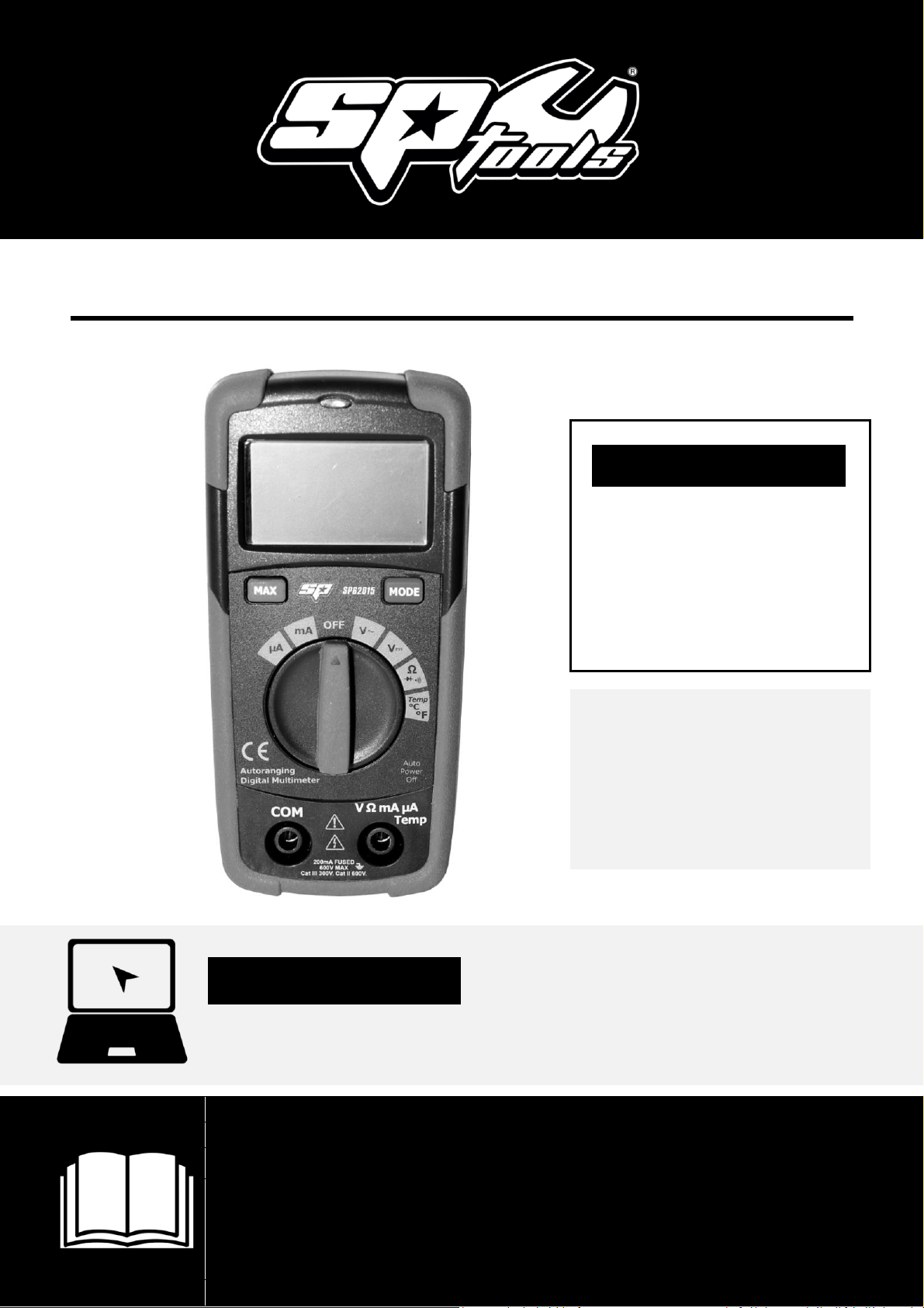
IMPORTANT
ALL PERSONS WHO ARE TO USE THIS EQUIPMENT MUST THOROUGHLY READ
AND UNDERSTAND THIS INSTRUCTION MANUAL PRIOR TO OPERATION.
SP62015
DIGITAL
MULTIMETER
WITH
TEMPERATURE
GAUGE
RETAIN THESE INSTRUCTIONS
AND ATTACH RECEIPT TO
MANUAL FOR FUTURE
REFERENCE
NOTE: Proof of purchase must be retained by
the customer as it will be required in the
event of a claim under warranty.
AFTER SALES SUPPORT:
AUSTRALIA: Visit the website’s contact page to get in
touch with your local service department.
WWW.SPTOOLS.COM
INTERNATIONAL: Use the county selector to get in touch
with your service department in your country or region.

2
CONTENTS
Safety Information 3
Safety Symbols 3
Controls and Jacks 4
Symbols and Annunciators 4
Specifications 5
DC Voltage (Auto-ranging) 5
AC Voltage (Auto-ranging) 6
DC Current (Auto-ranging for uA and mA) 6
Resistance (Auto-ranging) 6
Diode Test 7
Temperature 7
Audible continuity 7
0peration 7
DC Voltage Measurements 8
AC Voltage Measurements 8
DC Current Measurements 8
AC Current Measurements 9
Resistance Measurements 10
Continuity Check 10
Diode Test 10
Temperature Measurements 11
Non-contact Voltage (NCV) 11
Replacing the Battery 11
Battery Installation 12
Replacing the Fuses 12
Warranty Details 13

3
SAFETY INFORMATION
The following safety information must be observed to insure maximum
personal safety during
the operation at this meter:
•Do not use the meter if the unit or test leads look damaged, or if you suspect that the
meter is not operating properly
.
•Never ground yourself when taking electrical measurements. Do not touch exposed metal
pipes, outlets, fixtures, etc. Keep your body isolated from ground by using dry clothing,
rubber shoes, rubber mats or any approved insulating material.
•
Turn the power to off before testing circuit, cutting, unsoldering or breaking the
circuit. Small amounts of current can be dangerous.
•Use caution when working above 60V de or 30V ac rms. Such voltages pose a shock hazard.
•
When using the probes, keep your fingers behind the finger guards on the probes.
•
Measuring voltage which exceeds the limits of the multimeter maydamage the meter
and expose the operator to a shock hazard.Always recognize the meter voltage limit
as stated on the front of the meter.
•Never apply voltage or current to the meter that exceeds the specified
maximum.
SAFETY INFORMATION
This symbol adjacent to another symbol, terminalor operating
device indicates that the operator must refer to an explanation in
the Operating
Instructions to avoid personal injury or damage to
the
meter.
This
WARNING
symbol indicates a potentially hazardous situation,
which if not avoided, could result in death or serious injury.
This
CAUTION
symbol indicates a potentially hazardous situation,
which if not avoided, may result damage to the product.
This symbol advises that the terminal(s) so marked must not be
connected to a circuit point
at which the voltage with respect to
earth ground exceeds (in this case) 600 VAC or VDC.
This symbol adjacent to one or more terminals identifies them as being
associated with ranges that may, in normal use, be subjected to
particularly hazardous voltages. For maximum safety, the meter and its
test leads should not be handled when these terminals are energised.

4
CONTROLS AND JACKS
1)
2000 count Liquid Crystal Display with symbolic signs
2)
MAX. Hold push button
3)
Function switch
4)
COM (negative) input jack
5)
Positive input jack
6)
Mode push button: selection Continuity /Diode, AC/DC, Temperature(C/F)
7)
Non-contact voltage
SYMBOLS AND ANNUNCIATIONS
•Continuity •BAT Low Battery
•Diode • AUTO Auto Ranging
• AC Alternating Current or Voltage •DC Direct Current or Voltage
Input Limits
Function
Maximum Input
V DC or V AC
600V DC /AC
mA DCJAC
200mA DCJAC
Resistance, Diode test, Continuity Temperature
250V DCJAC
1
3
2
7
6
5
4

5
SPECIFICATIONS
The instrument complies with: EN61010-1 .
Insulation: Class2, Double insulation.
Overvoltage category: CATIII 300V CATII 600V
Display: 2000 counts LCD display with function indication.
Polarity: Automatic, (-) negative polarity indication.
Over range: "OL" mark indication.
Low battery indication: The "BAT" is displayed when the battery voltage drops
below the operating level.
Measurement rate: 2 times per second, nominal.
Auto power off: Meter automatically shuts down after approx. 15
minutes of inactivity.
Operating environment: 0°C to S0 °C (32 °F to 122 °F) at < 70% relative
humidity.
Storage temperature: -20 °C to 60°C (-4°F to 140 °F) at < 80% relative
humidity.
For inside use, max height: 2000m
Pollution degree: 2
Power: One12V battery
Dimensions: 108(H) x 53(W) x 32(D) mm
Weight: Approx.: 102g.
Accuracy is given at 18° to 28° - 65°F to 83°F, less than 70% RH.
DC Voltage (Auto-ranging)
Input Impedance: 10M
Ω
.
Maximum Input: 600V AC/DC rms
Range
Resolution
Accuracy
200.0mV
0.1mV
±0.5% of rdg ±4 dgts
2.000V
1mV
± 1.2% of rdg ± 2 dgts
20.00V
10mV
200.0V
100mV
600V
1V
±1.5% of rdg ± 2 dgts

6
AC Voltage (Auto-ranging)
Range
Resolution
Accuracy
2.000V
1mV
±1.2% of rdg ± 4 dgts
20.00V
10mV
±1.5% of rdg ± 3 dgts
200.0V
100mV
± 2.0% of rdg ± 4 dgts
600V
1V
Input Impedance: 10MΩ
Frequency Range: 50 to 60Hz
Maximum Input: 600V AC/DC rms.
DC Current (Auto-ranging for uA and mA)
Overload Protection: 0.2A/600V
Maximum Input: 200mA DC or 200mA AC rms on µA/mA ranges
Resistance (Auto-ranging)
Input Protection: 250V DC or 500V AC rms
Range
Resolution
Accuracy
200 .0µA
0.1µA
± 1.0% of rdg ± 3 dgts
2000µA
1µA
± 1.5% of rdg ± 3 dgts
20.00mA
10µA
200 .0mA
100µA
Range
Resolution
Accuracy
200.0
Ω
0.1
Ω
±1.5% of rdg ± 4 dgts
2.000k
Ω
1
Ω
±1.2% of rdg ± 2 dgts
20.00k
Ω
10
Ω
±1.5% of rdg ± 2 dgts
200.0kΩ
100
Ω
2.000 MΩ
1k
Ω
20.00M
Ω
10k
Ω
±2.0% of rdg ± 3 dgts

7
Diode Test
Open circuit voltage: 1.5V DC typical
Overload protection: 250V AC/DC rms.
Temperature
Sensor: K Thermocouple
Audible continuity
Audible threshold: Less than 100 Test current: <0.3mA
Overload protection: 250V AC/DC rms
OPERTATION
RISK OF ELECTRICAL SHOCK
Could result in fatal electrical shock
Risk of electrocution. High-voltage circuits, both AC and DC, are very dangerous and should
be measured with great care.
•
ALWAYS
turn the function switch to the OFF position when the meter is not in use.
This meter has Auto OFF that automatically shuts the meter OFF if 15 minutes elapse
between uses.
• If "OL" appears in the display during a measurement, the value
exceeds the
range you have selected. Change to a higher range.
Note:
On some low AC and DC voltage ranges, with the test leads not connected to a
device, the display may show a random, changing
reading. This is normal and is caused by
the high-input sensitivity. The reading will stabilize and give a proper measurement
when connected to a circuit.
Test current
Resolution
Accuracy
0.3mA typical
1 mV
±10% of rdg ± 5 dgts
Range
Resolution
Accuracy
-50°C- + 760 °C
1°c
±3% of rdg ± 5°C
-58°F- + 140
0°F
1°F
±3%
of
rdg
± 9°F

8
Mode Button
To select Diode/Continuity or DC/AC current, Temperature (C/ F).
Max Hold Button
The max Hold position is used to measure the maximum value.
The maximum measured value is up dated continuously. Press onceagain the button, will release
the hold and allow a further measurement.
DC Voltage Measurements
CAUTION
Do not measure DC voltages if a motor on the circuit is being switched ON or OFF.
Large voltage surges may occur that candamage the meter.
•
Set the function switch to the V DC position ("mV" will appear in the display).
•
Insert the black test lead, banana plug into the negative (COM) jack and the red test
lead, banana plug into the positive (V) jack.
•
Touch the test probe tips to the circuit under test. Be sure to observethe correct
polarity (red lead to positive, black lead to negative).
•
Read the voltage in the display. The display will indicate the properdecimal point
and value. If the polarity is reversed, the display will show (-) minus before the
value.
AC Voltage Measurements
RISK OF ELECTRICAL SHOCK
Could result in fatal electrical shock
•
Risk of Electrocution. The probe tips may not be long enough to contact the live parts
inside some 240V outlets for appliances because the contacts are recessed deep in the
outlets.As a result, the reading may show 0 volts when the outlet actually has voltage
on it. Make sure the probe tips are touching the metal contacts inside the outlet
before assuming that no voltage is present.
CAUTION
Do not measure AC voltages if a motor on the circuit is being switched ON or
OFF.
Large voltage surges may occur that candamage the meter.
•
Set the function switch to the V AC position.
•
Insert the black test lead, banana plug into the negative (COM) jack and the red test
lead, banana plug into the positive (V) jack.
•
Touch the test probe tips to the circuit under test.
Read the voltage in the display.
The display will indicate the properdecimal point, value and symbol (AC, V, etc).

9
DC Current Measurements
For current measurements up to 2000uA DC, set the function switchto the uA position and
insert the red test lead, banana plug into the(µA) jack.
•
For current measurements up to 200mA DC, set the function switch to the mA range
and insert the red test lead, banana plug into the (mA) jack.
•
Press the MODE button until "DC" appears in the display.
•
Remove power from the circuit under test, then open up the circuit
at the point
where you wish to measure current.
•
Touch the black test probe tip to the negative side of the circuit.Touch the red test
probe tip to the positive side of the circuit.
•
Apply power to the circuit.
•
Read the current in the display. The display will indicate the proper decimal point,
value and symbol.
AC Current Measurements
RISK OF ELECTRICAL SHOCK
To avoid electric shock, do not measure AC current on anycircuit whose
voltage exceeds 250V AC.
•
Insert the black test lead banana plug into the negative (COM) jack.
•
For current measurements up to 2000µA AC, set the function switchto the µA position
and insert the red test lead, banana plug into the (µA) jack.
•
For current measurements up to 200mA AC, set the function switchto the mA range
and insert the red test lead, banana plug into the (mA) jack.
•
Press the MODE button until "AC" appears in the display.
•
Remove power from the circuit under test, then open up the circuitat the point
where you wish to measure current.
•
Touch the black test probe tip to the negative side of the circuit. And touch the red
test probe tip to the positive side of the circuit.
•
Apply power to the circuit.
•
Read the current in the display. The display will indicate the properdecimal point,
value and symbol.

10
Resistance Measurements
RISK OF ELECTRICAL SHOCK
To avoid electric shock, disconnect power to the unit under test and discharge all
capacitors before taking any resistance measurements.
Remove the batteries and unplug the line cords.
•
Set the function switch to the position.
•
Insert the black test lead, banana plug into the negative (COM) jack
and the red test
lead, banana plug into the positive jack.
•
Touch the test probe tips across the circuit or part under test. It isbest to disconnect
one side of the part under test so the rest of thecircuit will not interfere with the
resistance reading.
•Read the resistance in the display. The display will indicate the proper
decimal point,
value and symbol.
Continuity Check
RISK OF ELECTRICAL SHOCK
To avoid electric shock, never measure continuity on circuitsor wires that have
voltage in them.
•
Set the function switch to the. position.
•
Insert the black lead, banana plug into the negative (-) jack (COM)
and the red test
lead, banana plug into the positive (+) jack
•
Press
the MODE button until the
symbol appears in the display.
•
Touch the test probe tips to the circuit or wire you wish to check.
•
If the resistance is less than approximately 30
Ω
, the audible signal will sound. The
display will also show the actual resistance.
Diode Test
RISK OF ELECTRICAL SHOCK
To avoid electric shock, do not test any diode that hasvoltage in it.
•
Set the function switch to
position
.
•Press the MODE button until the symbol appears in the display.
I
nsert the black test lead, banana plug into the negative (-) jack (COM) and the red
test lead, banana plug into the positive (+) jack.
•
Touch the test probe tips to the diode or semiconductor junctionyou wish to test.
Note
the meter reading.
•
Reverse the probe polarity by switching probe position.
Note
this
reading.
•
The
diode or junction can be evaluated as follows:

11
1.
If one reading shows a value and the other reading shows OL,the diode is good.
2.
If both readings show OL, the device is open.
3.
If both readings are very small or 0, the device is shorted.
Note
: The value indicated in the display during the diode check isthe forward voltage.
Temperature Measurements
RISK OF ELECTRICAL SHOCK
To avoid electric shock, disconnect both test probes from any source of voltage before
making a temperature measurement.
•If you wish to measure temperature in °F, set the function switch to the °F range. If you
wish to measure temperature in °C, set the function switch to the 0c range.
•Insert the black test lead, banana plug into the negative (COM) jack and the red test lead,
banana plug into the positive (V) jack, making sure to observe the correct polarity.
•Touch the Temperature Probe head to the part whose temperature you wish to measure.
Keep the probe touching the part under test until the reading stabilizes (about 30 seconds).
•Read the temperature in the display. The digital reading will indicate the proper decimal
point and value.
Warning: To avoid electric shock, be sure the thermocouple has been removed before
changing to another measurement function.
Non-contact Voltage (NCV)
The NCV function works on any rotary switch position.
•Test the detector on a known live circuit before use.
•Hold the top of the meter very close to the voltage source as shown.
•If voltage is present, the rim of the LCD display will flash a bright red.
Replacing the Battery
Warning: To avoid electric shock, disconnect the test leads from any source of voltage
before removing the battery door.
•When the batteries become exhausted or drop below the operating voltage, "BAT" will
appear in the right-hand side of the LCD display. The battery should be replaced.
•Follow instructions for installing battery
Dispose of the old battery properly.
Warning: To avoid electric shock, do not operate your meter until the battery door is in
place and fastened securely.

12
BATTERY INSTALLATION
RISK OF ELECTRICAL SHOCK
To avoid electric shock, disconnect the test leads from any source of voltage
before removing the battery door.
•Disconnect the test leads from the meter.
•Open the battery door by loosening the screw using a Phillips head screwdriver.
•Insert the battery into battery holder, observing the correct polarity.
•Put the battery door back in place. Secure with the two screws.
Warning: To avoid electric shock, do not operate the meter until the battery door is
in place and fastened securely.
Note: If your meter does not work properly, check the fuses and battery to make sure that
they are still good and that they are properly inserted.
REPLACING THE FUSES
RISK OF ELECTRICAL SHOCK
To avoid electric shock, disconnect the test leads from any source of voltage before
removing the fuse door.
•Disconnect the test leads from the meter and any item under test.
•Open the fuse door by loosening the screw on the door using a Phillips head screwdriver.
•Remove the old fuse from its holder by gently pulling it out.
•Install the new fuse into the holder.
•Always use a fuse of the proper size and value (0.2N 250V fast blow for the 200mA range),
•Put the fuse door back in place. Insert the screw and tighten it securely.
Warning: To avoid electric shock, do not operate your meter until the fuse door is in place
and fastened securely.

13
LIMITED WARRANTY
This Limited Warranty applies only to new products* distributed by SP Tools Pty Ltd (“SP Tools”). It is a condition of this Limited
Warranty Policy that the purchaser read the owner’s manual for the product and only use the product to the extent or for the
purposes stated therein. The purchaser must also ensure that all servicing requirements are completed as listed in the owner’s
manual (said servicing is at the owner’s expense). We recommend that all servicing is completed by an authorised service agent and
that records of said servicing are retained by the purchaser as proof in the event of a warranty claim.
Whilst the owner’s manual, packaging, and/or other documentation supplied with SP Tools’ products may provide details in respect
of a Limited Warranty, the terms set out herein supersede these matters, and this Limited Warranty applies in their place. This
warranty is no less advantageous than otherwise described in such other documentation.
SP Tools agrees, subject to the terms and conditions specified below, to repair or replace at SP Tools’ cost, the product purchased by
you when the product does not perform in accordance with its specifications during the limited warranty period, due to any fault in
manufacturing, materials and/or workmanship. SP Tools is not liable to repair or replace products that the purchaser uses in a
manner that is inconsistent with the owner’s manual or in the circumstances set out in paragraphs 1.1 – 1.7 below.
The benefits to the purchaser under this warranty are in addition to other rights and remedies under the Competition and Consumer
Act 2010 (Cth). The limited warranty period, within which a defect in the product must appear, commences from the date of
purchase and ceases on expiration of the specified term below.
THE LIMITED WARRANTY PERIOD
• SP Speciality Tools –12 Months
THE PURCHASERS ATTENTION IS DRAWN TO THE FOLLOWING
To the extent permitted by law and subject to this Limited Warranty, and as part of the terms of the sale of the equipment or part
thereof: SP Tools shall not be liable for any form of loss, damage, cost, injury or harm of any kind (whether direct, indirect, special
or consequential) howsoever arising from the use or supply of the equipment to the purchaser.
EXCLUSIONS TO LIMITED WARRANTY POILICY
This Limited Warranty will not apply where the equipment or any part thereof:
1.1 Fails due to an accident (including liquid spillage), abuse, misuse, neglect or normal wear and tear;
1.2 Has been used in a manner other than for which it was originally designed;
1.3 Has been tampered with or is otherwise than as supplied by SP Tools;
1.4 Where any damage, malfunction or other failure of the equipment or any part thereof resulted directly or indirectly from
unauthorized persons, adjusting or failing to adjust any part requiring normal maintenance and service (examples include
adjustment of tappets, air filter maintenance, lubrication and tightening of screws nuts and bolts);
1.5 Malfunctions due to the use of defective or incompatible accessories;
1.6 Is damaged by lightning or thunderstorm activity; or
1.7 Has been transported to a country where no authorised Service Agents exist.
CLAIMING WARRANTY
This Limited Warranty may be claimed on in the following manner:
2.1 In order to make a claim under this Limited Warranty, the purchaser must deliver the equipment or any part thereof to an
SP Tools authorised repair agent and pay all costs of transportation and all costs incidental to making a claim under
this Limited Warranty. The purchaser must first contact SP Tools (contact details described above) and request the
delivery address of an SP Tools authorised repair agent.
2.2 The purchaser must deliver to the repair agent written reasons why the purchaser considers that the purchaser has a claim
under this Limited Warranty and must provide all necessary details, including:
•The place, date and from whom the unit or part was purchased.
•The unit or part involved, Model and Serial Number.
•The defect, malfunction or failure in respect of which the claim is being made.
•Proof of service of the unit or part (if applicable)
•Proof of purchase in respect of the unit or part.
2.3 If the Limited Warranty claim is valid, the repair agent will carry out repairs and return the product at no charge to the
purchaser. These repairs are limited to the Limited Warranty fault identified and as such will not include any other faults due to
misuse, abuse, failure to maintain, fair wear and tear or the replacement of serviceable items such as oil, spark plugs, air filters,
fuel etc.
Our goods come with guarantees that cannot be excluded under Consumer Law. You are entitled to a replacement or refund for a
major failure and for compensation for any other reasonably foreseeable loss or damage. You are also entitled to have the goods
repaired or replaced if the goods fail to be of acceptable quality and the failure does not amount to a major failure.
Note: Units which are failing to perform in accordance with specifications due to non-warrantable causes will be subject to freight,
repair and or quote charge
Table of contents
Other SP tools Multimeter manuals


