BizLine 780 313 User manual

• EN DIGITAL CLAMP MULTIMETER
Instruction Manual ............................................................................... p.2
• FR PINCE AMPÈREMÉTRIQUE
Mode d'emploi ....................................................................................... p.8
• NL DIGITALE KLEMMULTIMETER
Gebruiksaanwijzing .......................................................................... p.14
• DE DIGITALES ZANGEN-UNIVERSALMESSGERÄT
Anwendung............................................................................................ p.20
• SE DIGITAL KLÄMMULTIMETER
Bruksanvisning ................................................................................... p.26
• FI DIGITAALINEN PURISTUSMONITOIMIMITTARI
Käyttöopas ............................................................................................ p.32
• NO DIGITALT TANGMULTIMETER
Instruksjonshåndbok........................................................................ p.38
• IT PINZA AMPEROMETRICA DIGITALE
Manuale d’uso ..................................................................................... p.44
• ES PINZA AMPERIMETRICA DIGITAL
Manual de instrucciones ................................................................ p.50
BIZ 780 313
SE E-nr 42 023 21
Snro 67 045 08
Exe_Notice_BIZ 780313.indd 1 15/05/2019 17:35
EN
2
OPERATING INSTRUCTION
1000A DC/AC CLAMP METER
Safety
International Safety Symbols
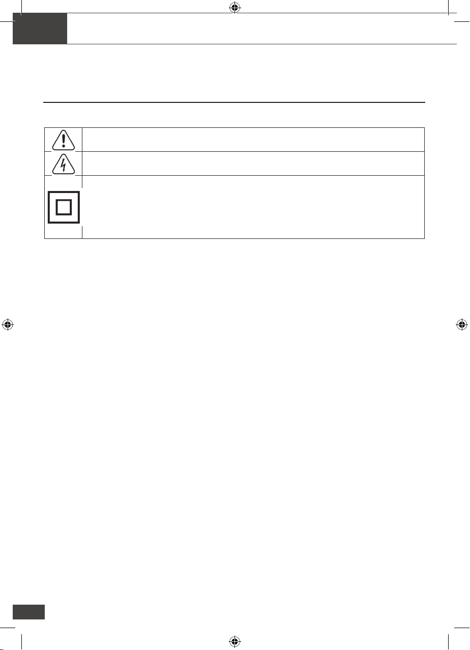
This symbol, adjacent to another symbol or terminal, indicates the user must refer to the
manual for further information.
This symbol, adjacent to a terminal, indicates that, under normal use, hazardous voltages
may be present
Double insulation
CAT II Measurement Category II is applicable to test and measuring circuits connected
directly to utilization points(socket outlets and similar points) of the
low-voltage MAINS installation.
CAT III Measurement Category III is applicable to test and measuring circuits connected to
the distribution part of the building’s low voltage MAINS installation.
SAFETY NOTES
• Do not exceed the maximum allowable input range of any function
• Do not apply voltage to meter when resistance function is selected.
• Set the function switch OFF when the meter is not in use.WARNINGS
•
WARNINGS
• Set function switch to the appropriate position before measuring.
• When measuring volts do not switch to current/resistance modes.
• Do not measure current on a circuit whose voltage exceeds 240V.
• When changing ranges using the selector switch always disconnect the test leads from the circuit under
test.
• Do not exceed the maximum rated input limits.
CAUTIONS
Improper use of this meter can cause damage, shock, injury or death. Read and understand this user
manual before operating the meter.
Always remove the test leads before replacing the battery.
Inspect the condition of the test leads and the meter itself for any damage before operating the meter.
Repair or replace any damage before use.
Use great care when making measurements if the voltages are greater than 25VAC rms or 35VDC. These
voltages are considered a shock hazard.
Remove the battery if the meter is to be stored for long periods.
Always discharge capacitors and remove power from the device under test before performing Diode,
Resistance or Continuity tests.
• Voltage checks on electrical outlets can be difcult and misleading because of the uncertainty of
connection to the recessed electrical contacts. Other means should be used to ensure that the terminals
are not «live».
• If the equipment is used in a manner not specied by the manufacturer, the protection provided by the
equipment may be impaired.
The safety standard for a stylus is that it conforms to CATIII 1000V CATIV 600V when the stylus is
wearing a protective cap, and only CATII 1000V when the stylus cap is removed.
Exe_Notice_BIZ 780313.indd 2 15/05/2019 17:35
Input Limits
Function Maximum Input
A AC 1000 A
V DC, V AC 600 V DC/AC
Resistance, Diode, Continuity, Capacitance, Frequency, Duty
Cycle, Test
250 V DC/AC
Temperature (°C/°F) 60V DC/24V AC
EN
3
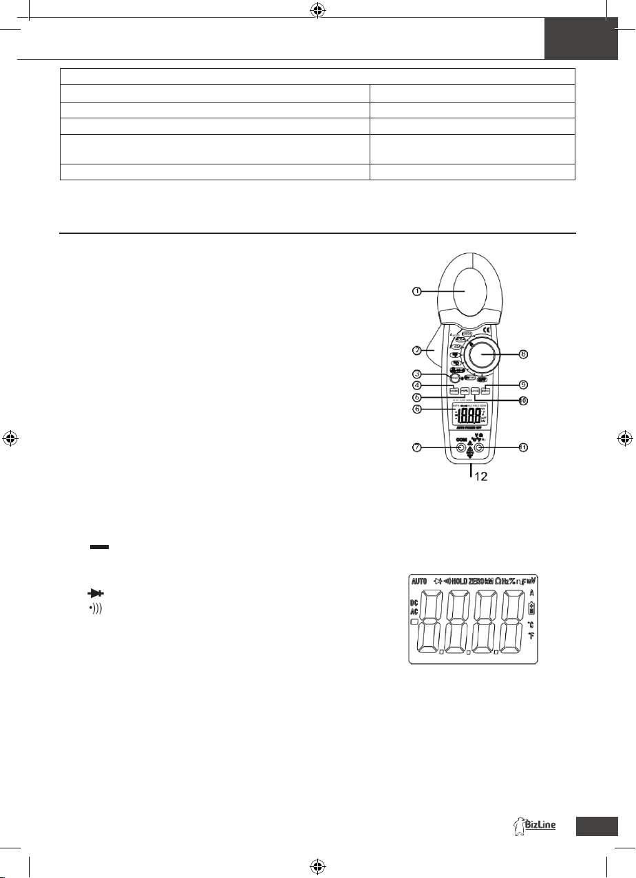
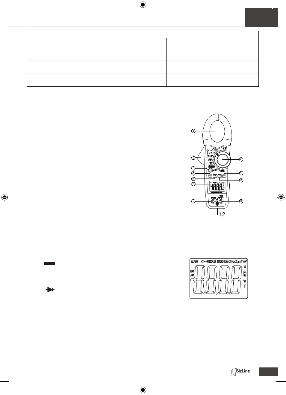
Meter Description
1. Current clamp
2. Clamp trigger
3. Data Hold and Backlight button
4. Mode select button
5. Hz/% button
6. LCD display
7. COM input jack
8. Rotary Function swith
9. ZERO button
10. Range select button
11. V Ω °C/°F jack
12. Battery compartment on rear
1. AC DC AC (alternating current) and DC (direct currrent)
2. Minus sign
3. 8.8.8.8 4000 count (0 to 3999) measurement reading
4. AUTO AutoRange mode
5. Diode test mode
6. Audible Continuity
7. HOLD Data Hold mode
9.°C,°F, µ,m,V,A,K,M,Ω , Units of measure list
Exe_Notice_BIZ 780313.indd 3 15/05/2019 17:35

EN
4
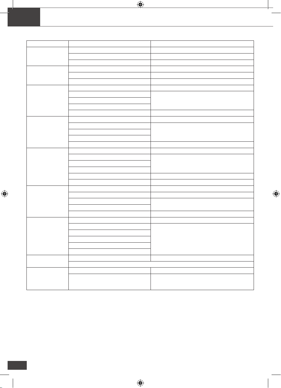
Specications
Function Range & Resolution Accuracy (% of reading)
DC Current
40,00 AAC ± (2,8 % + 10 digits)
400,0 AAC ± (2,8 % + 5 digits)
1000 AAC ± (3,0 % + 5 digits)
AC Current
40,00 AAC ± (3,0 % + 10 digits)
400,0 AAC ± (3,0 % + 5 digits)
1000 AAC ± (3,0 % + 5 digits)
DC Voltage
400.0 mVDC ± (0,8 % + 3 digits)
4,000 VDC
± (1,5 % + 3 digits)40,00 VDC
400,0 VDC
600 VDC ± (2,0 % + 3 digits)
AC Voltage
400,0 mVAC ± (0,8 % + 20 digits)
4,000 VAC
± (1,8 % + 5 digits)40,00 VAC
400,0 VAC
600 VAC ± (2,5 % + 5 digits)
Resistance
400,0 Ω ± (1,0 % + 4 digits)
4,000 kΩ
± (1,5 % + 2 digits)40,00 kΩ
400,0 kΩ
4,000 MΩ ± (2,5 % + 3 digits)
40,00 MΩ ± (3,5 % + 5 digits)
Capacity
40,00 nF ± (5,0 % + 100 digits)
400,0 nF ± (3,0 % + 5 digits)
4,000 μF ± (3,5 % + 5 digits)
40,00 μF
100,0 μF ± (5,0 % + 5 digits)
Frequency
5,000 Hz ± (1,5 % + 5 digits)
50,00 Hz
± (1,2% + 2 digits)
Sensibilité : 10 Vrms min.
500,0 Hz
5,000 kHz
50,00 kHz
100,0 kHz
Duty Cycle 0,5 à 99,0 % ± (1,2 % + 2 digits)
Pulse width: 100μs - 100ms, Frequency: 5.000Hz ~ 100.0kHz
Temp (type-K)
(probe accuracy
not included)
-20 to 1000 °C ± (3,0 % + 5 °C)
-4 to 1832 °F ± (3,0 % + 7 °F)
Note: No Autoranging & 400mV AC Voltage Range
Exe_Notice_BIZ 780313.indd 4 15/05/2019 17:35
EN
5
Clamp size Opening 1.2» (30mm) approx
Diode Test Test current of 0.3mA typical; Open circuit voltage 1.5V DC
typical.
Continuity Check Threshold <100 Ω; Test current < 1mA
Low Battery Indication “ ” is displayed
Overrange Indication “OL” is displayed
Measurements Rate 2 per second, nominal
Input Impedance 7.8M Ω (VDC and VAC)
Display 4000 counts LCD
AC Current 50/60Hz (AAC)
AC Voltage bandwidth 50/60Hz (VAC)
Operating Temperature 14 to 122oF (-10 to 50oC)
Storage Temperature -14 to 140oF (-30 to 60oC)
Relative Humidity 90%(0oC to 30oC); 75%(30oC to 40oC); 45%(40oC to 50oC)
Altitude Operating: 3000m; Storage 10,000m
Over voltage Category III 600V
Battery One “9V” Battery
Auto OFF approx. 35 minutes
Dimensions/Weight 229x80x49mm/303g
Safety For indoor use and in accordance with Overvoltage
Category II, Pollution Degree 2. Category II includes local
level, appliance, portable equipment, etc., with transient
overvoltages less than Overvoltage Cat. III
Operation
NOTES : Read and understand all warning and precaution statements listed in the safety section
of this operation manual prior to using this meter. Set the function select switch to the
OFF position when the meter is not in use.
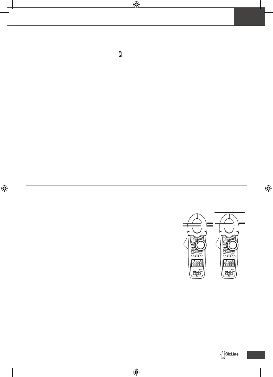
DC/AC Current Measurements
WARNING: Ensure that the test leads are disconnected from the meter before
making current clamp measurements.
1. Set the Function switch to the 1000A or 400A or
40A range. If the range of the measured is not known, select the higher
range rst then move to the lower range if necessary.
2. Select AC or DC with the MODE button.
3. Press the trigger to open jaw. Fully enclose one conductor
to be measured.
4. The clamp meter LCD will display the reading.
DC/AC Voltage Measurements
1. Insert the black test lead into the negative COM terminal and the red
test lead into the positive Vterminal.
2. Set the function switch to the V position.
3. Select AC or DC with the MODE button.
4. Connect the test leads in parallel to the circuit under test.
5. Read the voltage measurement on the LCD display.
No Yes
Exe_Notice_BIZ 780313.indd 5 15/05/2019 17:35
EN
6
Resistance and Continuity Measurements
1. Insert the black test lead into the negative COM terminal and the red test lead into the positive terminal.
2. Set the function switch to the Ωposition.
3. Use the multifunction MODE button to select resistance.
4. Touch the test probe tips across the circuit or component under test. It is best to disconnect one side of the device under
test so the rest of the circuit will not interfere with the resistance reading.
5. For Resistance tests, read the resistance on the LCD display.
6. For Continuity tests, if the resistance is < 100 , a tone will sound.
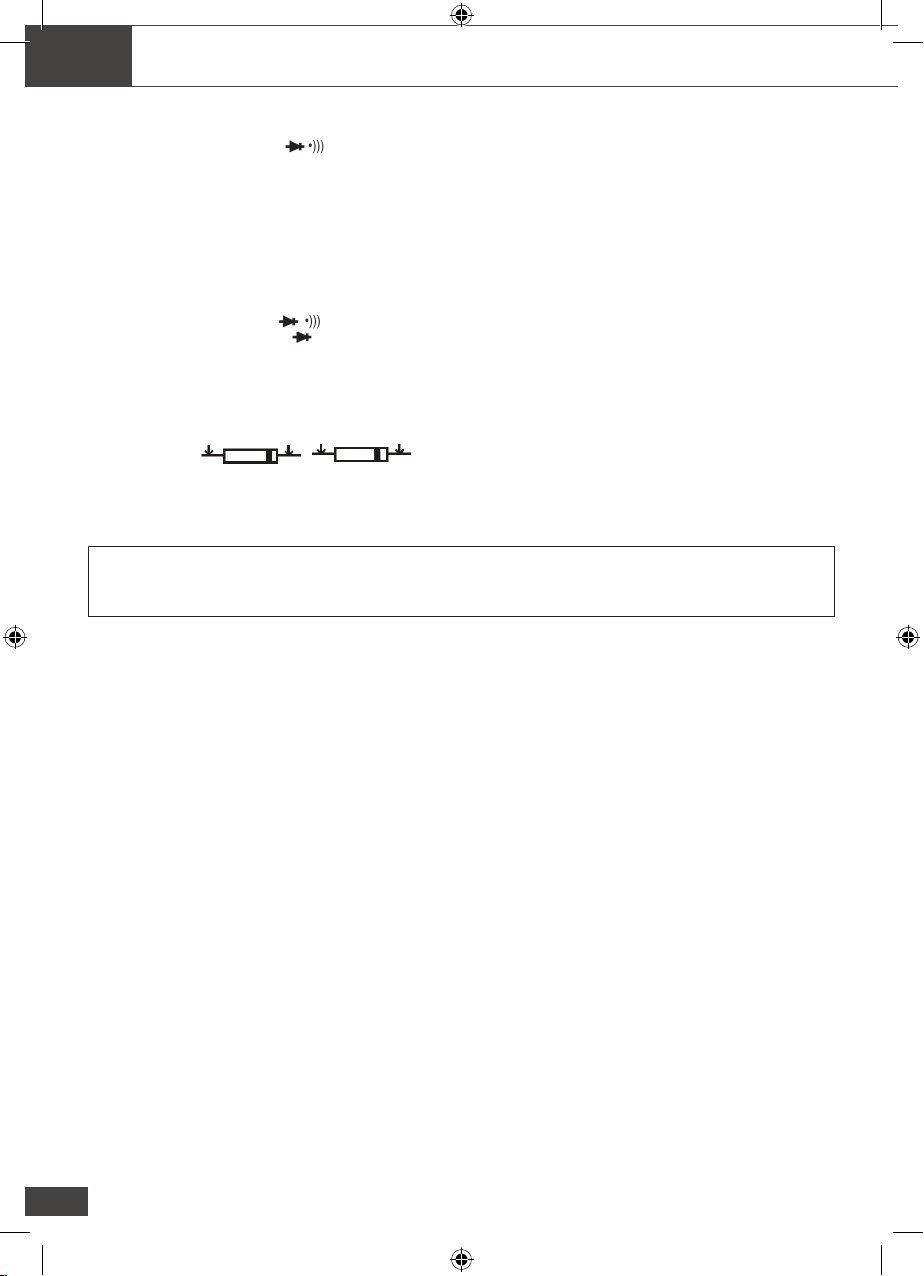
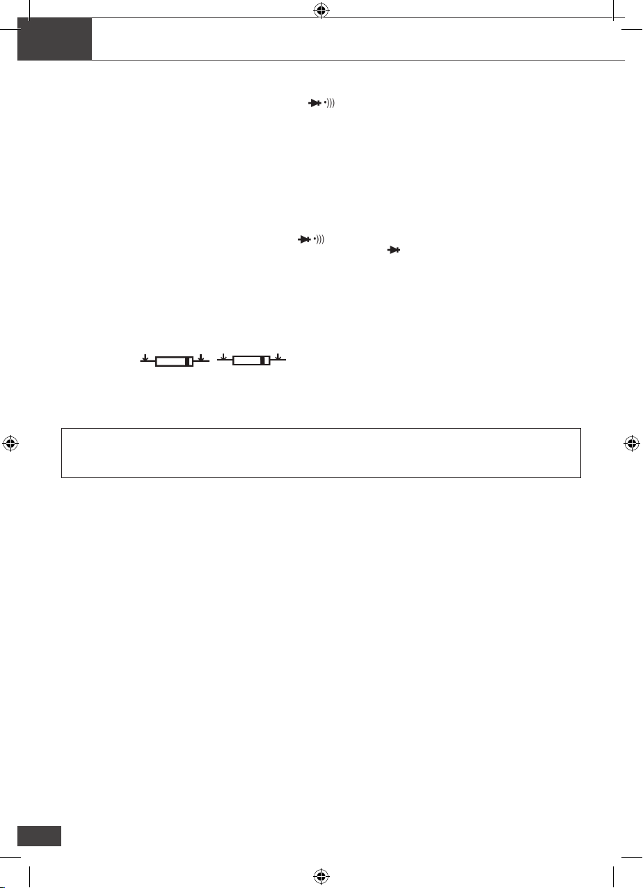
Diode Measurements
1. Insert the black test lead banana plug into the negative COM jack and the red test lead banana plug into the positive
diode jack.
2. Turn the rotary switch to the position.
3. Press the MODE button until « » appears in the display.
4. Touch the test probes to the diode under test. Forward voltage will indicate 0.4V to 0.7V. Reverse voltage will indicate
"OL". Shorted devices will indicate near 0mV and an open device will indicate "OL" in both polarities.
Sonde
rouge
Sonde
noire
Sonde
noire
Sonde
rouge
Test direct Test inverse
Capacitance Measurements
WARNING : To avoid electric shock, disconnect power to the unit under test and discharge all capacitors before taking
any capacitance measurements. Remove the batteries and unplug the line cords.
1. Set the rotary function switch to the cap position.
2. Insert the black test lead banana plug into the negative (COM) jack.
Insert the red test lead banana plug into the positive (V) jack.
3. Touch the test leads to the capacitor to be tested.
4. Read the capacitance value in the display
Frequency or % duty cycle measurements
1. Set the function switch to the V position.
2. Insert the black lead banana plug into the negative COM jack and the red test lead banana plug into the positive V
jack.
3. Select Hz or % duty with the Hz/% button.
4. Touch the test probe tips to the circuit under test.
5. Read the frequency on the display. Mesures de la température
Temperature Measurements
WARNING: To avoid electric shock, disconnect both test probes from any source of voltage before making a
temperature measurement.
1. Set the function switch to TEMP.
2. Insert the Temperature Probe into the negative (COM) and the V jacks, making sure to observe the correct polarity.
3. Select oC or oF with the MODE button.
4. Touch the Temperature Probe head to the part whose temperature you wish to measure. Keep the probe touching the
part under test until the reading stabilizes (about 30 seconds).
5. Read the temperature in the display. The digital reading will indicate the proper decimal point and value.
WARNING: To avoid electric shock, be sure the thermocouple has been removed before changing to another
measurement function
Exe_Notice_BIZ 780313.indd 6 15/05/2019 17:35

EN
7
Data Hold and Backlight
To freeze the LCD meter reading, press the data hold button. The data hold button is located on the left side of the meter
(top button). While data hold is active, the HOLD display icon appears on the LCD. Press the data hold button again to
return to normal operation.
Note: The HOLD feature will activate when the Backlight is turned on. Press the HOLD key again to exit Hold.
The backlight function illuminates the display and is used when the ambient light to too low to permit viewing of the
displayed readings. Press the HOLD) button for one second to turn the backlight on and press the button a second
time to turn the backlight off.
Manual Ranging
The meter turns on in the autoranging mode. Press the Range button to go to manual ranging. Each press of the range
button will step to the next range as indicated by the units and decimal point location. Press and hold the Range button for
two seconds to return to autoranging. Manual ranging does not function in the AC Current , Diode and Continuity check
functions
Battery Replacement
1. Remove the one rear Phillips head screw
2. Open the battery compart
3. Replace the Requires one (NEDA1604, 6F22 006P)
4. Re-assemble the meter
The rating for the test Probe is CAT III 1000V 10A
Exe_Notice_BIZ 780313.indd 7 15/05/2019 17:35

FR
8
GUIDE DE L’UTILISATEUR
PINCE AMPEREMETRIQUE 1000 A CC/CA
Sécurité
Symboles internationaux de sécurité
Ce symbole apposé à proximité d’un autre symbole ou d’une borne indique que l’utilisateur
doit consulter le manuel pour plus d’informations.
Ce symbole apposé à proximité d’une borne indique que, dans des conditions d’utilisation
normales, des tensions dangereuses peuvent être présentes.
Isolation double
CAT II La Catégorie de sécurité II concerne les tests et mesures des circuits directement
connectés aux points d’utilisation (prises et points similaires) d’une installation basse
tension.
CAT III La Catégorie de sécurité III concerne les tests et mesures des circuits connectés à
la partie distribution de l’installation basse tension du bâtiment.
CONSIGNES DE SECURITE
• Ne dépassez pas la gamme d’entrées maximales autorisées pour une fonction.
• Ne mettez pas l’appareil sous tension lorsque la fonction de résistance est sélectionnée.
• Positionnez le sélecteur de fonction sur OFF lorsque vous n’utilisez pas l’appareil.
AVERTISSEMENTS
• Positionnez le sélecteur de fonction sur la position appropriée avant de procéder à la mesure.
• Lorsque vous mesurez une tension, ne positionnez pas le sélecteur en mode courant/résistance.
• N’effectuez aucune mesure de courant sur un circuit dont la tension est supérieure à 240 V.
• Lorsque vous utilisez le sélecteur pour changer de gamme, débranchez toujours les ls d’essai du
circuit testé.
• Ne dépassez pas les limites d’entrée maximales.
PRECAUTIONS
Toute utilisation inappropriée de l’appareil peut entraîner des dommages matériels et corporels, des
décharges électriques, voire la mort. Lisez et comprenez le présent manuel avant d’utiliser l’appareil.
Débranchez toujours les ls d’essais avant de remplacer la pile.
Vériez l’état des ls d’essai et de l’appareil avant de l’utiliser. Réparez ou remplacez tout élément
défectueux avant toute utilisation.
Faites preuve d’une extrême prudence lors de la mesure de tensions supérieures à 25 VCA rms ou 35
VCC. Ces tensions sont considérées comme dangereuses. Retirez la pile si l’appareil doit être stocké
pendant une période prolongée.
Déchargez toujours les condensateurs et coupez l’alimentation des dispositifs testés avant d’effectuer
des essais de diode, de résistance ou de continuité.
• Les vérications de tension sur les prises de courant peuvent se révéler difciles et trompeuses à
cause de l’incertitude quant aux branchements aux contacts électriques encastrés. Vous devez utiliser
d’autres moyens pour vérier que les bornes ne sont pas « sous tension ».
• Si vous utilisez l’équipement selon des modalités non spéciées par le fabricant, la protection qu’il
assure peut être compromise.
Norme de protection CATIII 1000 V et CATIV 600 V lorsque la sonde d’essai est équipée d’un capuchon
ou seulement CATII 1000 V en l’absence de capuchon sur la sonde d’essai.
Exe_Notice_BIZ 780313.indd 8 15/05/2019 17:35

Limites d’entrée
Fonction Entrée maximale
A AC 1000 A
VCC, VCA 600 V DC/AC
Résistance, Diode, Continuité, Capacité, Fréquence,
Cycle opératoire, Test
250 V DC/AC
Température (°C/°F) 60 VCC/24 VCA
FR
9
Description de la pince
1. Pince ampèremétrique
2. Gâchette d’ouverture de la pince
3. Touche de maintien des données
et de rétroéclairage
4. Sélecteur des modes
5. Touche Hz/%
6. Écran LCD
7. Borne d’entrée COM
8. Sélecteur de fonctions rotatif
9. Touche de mise à zéro
10. Sélecteur de gamme
11. Borne V Ω °C/°F
12. Compartiment pile à l’arrière
1. AC DC AC (courant alternatif) and DC (courant continu)
2. Signe moins
3. 8.8.8.8 4000 mesures (0 to 3999)
4. AUTO Mode de sélection de gamme
5. Mode test diode
6. Continuité sonore
7. HOLD Mode de maintien des données
8.°C,°F, µ,m,V,A,K,M,Ω , Unités de mesure
Exe_Notice_BIZ 780313.indd 9 15/05/2019 17:35
FR
10
Spécications
Fonction Gamme et résolution Précision (%)
Courant DC
40,00 AAC ± (2,8 % + 10 chiffres)
400,0 AAC ± (2,8 % + 5 chiffres)
1000 AAC ± (3,0 % + 5 chiffres)
Courant AC
40,00 AAC ± (3,0 % + 10 chiffres)
400,0 AAC ± (3,0 % + 5 chiffres)
1000 AAC ± (3,0 % + 5 chiffres)
Tension DC
400.0 mVCC ± (0,8 % + 3 chiffres)
4,000 VCC
± (1,5 % + 3 chiffres)40,00 VCC
400,0 VCC
600 VCC ± (2,0 % + 3 chiffres)
Tension AC
400,0 mVCA ± (0,8 % + 20 chiffres)
4,000 VCA
± (1,8 % + 5 chiffres)40,00 VCA
400,0 VCA
600 VCA ± (2,5 % + 5 chiffres)
Résistance
400,0 Ω ± (1,0 % + 4 chiffres)
4,000 kΩ
± (1,5 % + 2 chiffres)40,00 kΩ
400,0 kΩ
4,000 MΩ ± (2,5 % + 3 chiffres)
40,00 MΩ ± (3,5 % + 5 chiffres)
Capacité
40,00 nF ± (5,0 % + 100 chiffres)
400,0 nF ± (3,0 % + 5 chiffres)
4,000 μF ± (3,5 % + 5 chiffres)
40,00 μF
100,0 μF ± (5,0 % + 5 chiffres)
Fréquence
5,000 Hz ± (1,5 % + 5 chiffres)
50,00 Hz
± (1,2% + 2 chiffres)
Sensibilité : 10 Vrms min.
500,0 Hz
5,000 kHz
50,00 kHz
100,0 kHz
Cycle opératoire 0,5 à 99,0 % ± (1,2 % + 2 chiffres)
Largeur d'impulsion : 100 µs - 100 ms, Fréquence : 5,000 Hz ~ 100,0 kHz
Température
(type K)
(hors précision
de la sonde)
-20 à 1000 °C ± (3,0 % + 5 °C)
-4 à 1832 °F ± (3,0 % + 7 °F)
Remarque : Pas de sélection de gamme automatique et gamme de tension de 400 mVCA
Exe_Notice_BIZ 780313.indd 10 15/05/2019 17:35

FR
11
Dimension de la pince Ouverture de 1,2" (30 mm) environ
Test de diode Courant de test de 0,3 mA type. Tension de circuit ouvert de
1,5 VCC type.
Contrôle de continuité Seuil < 100 Ω. Courant de test < 1 mA
Indicateur pile faible " " s’afche
Indicateur de dépassement de gamme "OL" s’afche
Fréquence de mesure 2 par seconde, nominal
Impédance en entrée 7,8 MΩ (VCC et VCA)
Écran LCD 4000 mesures
Courant AC 50/60 Hz (AAC)
Largeur de bande tension AC 50/60 Hz (VCA)
Température d’utilisation 14 à 122 oF (-10 à 50 oC)
Température de stockage -14 à 140 oF (-30 à 60 oC)
Humidité relative 90 % (de 0 oC à 30 oC), 75% (de 30 oC à 40 oC), 45 % (de 40 oC à 50 oC)
Altitude Utilisation : 3 000 m. Stockage : 10 000 m
Surtension Catégorie III 600 V
Pile Une pile 9 V
Mise hors tension automatique au bout de 35 minutes environ
Dimensions/Poids 229x80x49 mm/303 g
Sécurité Pour utilisation intérieure et Surtension Catégorie II, Degré de
pollution 2. La Catégorie II comprend le niveau local, l’appareil,
l’équipement portable, etc. avec surtensions transitoires
inférieures à la surtension Catégorie III
Utilisation
REMARQUES : Lisez et comprenez tous les messages d’avertissement et deprécaution de ce
manuel avant d’utiliser l’appareil. Positionnez le commutateur de fonctions sur OFF
lorsque vous n’utilisez pas l’appareil.
Mesures de courant AC/DC
AVERTISSEMENT : Vériez que les ls d’essai sont débranchés de
la pince avant d’effectuer toute mesure de courant avec la pince.
1. Positionnez le sélecteur de fonctions rotatif sur la gamme 1000 A
ou 400 A ou 40 A. Si vous ne connaissez pas la gamme du dispositif
mesuré, sélectionnez d’abord la gamme la plus élevée puis passez à
la gamme inférieure si nécessaire.
2. Positionnez le sélecteur MODE sur AC ou DC.
3. Appuyez sur la gâchette pour ouvrir la mâchoire de la pince.
Refermez-la entièrement autour du conducteur à mesurer.
4. L’écran LCD de la pince afche la mesure.
Mesures de tension AC/DC
1. Branchez le l de test noir sur la borne négative COM et le l de test
rouge sur la borne positive V.
2. Positionnez le sélecteur de fonctions rotatif sur V.
3. Positionnez le sélecteur MODE sur AC ou DC.
4. Branchez les ls de test en parallèle sur le circuit testé.
5. L’écran LCD de la pince afche la mesure.
Non Oui
Exe_Notice_BIZ 780313.indd 11 15/05/2019 17:35
FR
12
Mesures de la résistance et de la continuité
1. Branchez le l de test noir sur la borne négative COM et le l de test rouge sur la borne positive.
2. Positionnez le sélecteur de fonctions rotatif sur Ω .
3. Sélectionnez la résistance à l’aide du sélecteur MODE.
4. Mettez les sondes d’essai en contact avec le circuit ou composant testé. Il est recommandé de débran-
cher un côté du dispositif testé pour que le reste du circuit ne perturbe pas la mesure de la résistance.
5. Pour les tests de résistance, la mesure s’afche sur l’écran LCD.
6. Pour les tests de continuité, si la résistance est < 100 Ω, un signal sonore retentit.
Test de diode
1. Introduisez la che banane du l d’essai noir dans le connecteur négatif COM et la che banane du l
d’essai rouge dans le connecteur positif.
2. Positionnez le commutateur de fonctions sur
3. Appuyez sur le sélecteur MODE jusqu’à ce que l’écran afche " ".
4. Mettez les sondes d’essai en contact avec la diode testée. La tension directe afchée est de 0,4 V à
0,7 V. La tension inverse afche "OL". Lorsque la mesure est proche de 0 mV, cela signie que le dis-
positif est court-circuité. Si la mesure afche "OL" sur les deux polarités, cela signie que le dispositif
est ouvert.
Sonde
rouge
Sonde
noire
Sonde
noire
Sonde
rouge
Test direct Test inverse
Mesures de la capacité
AVERTISSEMENT : Pour éviter tout choc électrique, coupez l’alimentation électrique de l’appareil testé
et déchargez tous les condensateurs avant d’effectuer une mesure de capacité.
Retirez les piles et débranchez les ls d’essai.
1. Positionnez le sélecteur de fonctions rotatif sur Cap.
2. Introduisez la che banane du l d’essai noir dans le connecteur négatif (COM).
Introduisez la che banane du l d’essai rouge dans le connecteur positif (V).
3. Mettez les ls d’essai en contact avec le condensateur à tester.
4. L’écran afche la mesure.
Mesures de la fréquence ou du % du cycle opératoire
1. Positionnez le commutateur de fonctions sur V.
2. Introduisez la che banane du l d’essai noir dans le connecteur négatif COM et la che banane
du l d’essai rouge dans le connecteur positif V.
3. Positionnez le sélecteur Hz/% sur Hz ou %.
4. Mettez les sondes d’essai en contact avec le circuit testé.
5. L’écran afche la fréquence mesurée.
Mesures de la température
AVERTISSEMENT : Pour éviter tout choc électrique, débranchez les deux sondes d’essai de toute
source de tension avant de procéder à une mesure de température.
Exe_Notice_BIZ 780313.indd 12 15/05/2019 17:35

FR
13
1. Positionnez le sélecteur de fonctions rotatif sur TEMP.
2. Introduisez la sonde de température dans le connecteur négatif COM et dans le connecteur V. Respec-
tez la polarité.
3. Positionnez le sélecteur MODE sur °C ou °F.
4. Appliquez la pointe de la sonde de température sur la partie dont vous souhaitez mesurer la tempéra-
ture. Maintenez la sonde en contact avec la partie à mesurer jusqu’à stabilisation de la valeur (pendant
environ 30 secondes).
5. L’écran afche la température mesurée. L’afchage numérique présente la valeur avec décimale.
AVERTISSEMENT : Pour éviter tout choc électrique, vériez que le thermocouple a bien été débranché
avant de passer à une autre fonction de mesure.
Maintien des données et rétroéclairage
Appuyez sur la touche de maintien des données pour ger la mesure afchée sur l’écran LCD. La touche
de maintien des données se trouve sur le côté gauche de la pince (bouton du haut). Lorsque le maintien
des données est actif, l’icône HOLD s’afche sur l’écran LCD. Appuyez de nouveau sur la touche de
maintien des données pour revenir au mode de fonctionnement normal.
Remarque : La fonction HOLD s’active lorsque le rétroéclairage est activé. Appuyez de nouveau
sur la touche HOLD pour désactiver la fonction.
La fonction rétroéclairage éclaire l’écran en cas de faible luminosité pour faciliter la visualisation des
valeurs afchées. Appuyez sur la touche (HOLD) pendant une seconde pour activer le rétroéclairage
puis appuyez une deuxième fois sur la touche pour désactiver le rétroéclairage.
Sélection de gamme manuelle
A l’allumage, l’appareil est en mode sélection de gamme automatique. Appuyez sur la touche Range
pour accéder à la sélection de gamme manuelle. Chaque appui sur la touche RANGE vous fait passer à
la gamme suivante comme indiqué par les unités et l’emplacement de la décimale. Appuyez sur la touche
Range et maintenez-la enfoncée pendant deux secondes pour reprendre le mode sélection de gamme
automatique. La sélection de gamme manuelle n’est pas disponible pour les fonctions de mesures de
courant AC, de test de diode et de contrôle de continuité.
Remplacement de la pile
1. Déposez la vis Phillips du compartiment à pile situé en face arrière.
2. Ouvrez le compartiment à pile.
3. Remplacez la pile 9 V par une pile neuve (NEDA1604, 6F22 006P).
4. Refermez le compartiment à pile.
La sonde d’essai est homologuée Catégorie III, 1000 V, 10 A
Nom du fabricant : SHENZHEN EVERBEST MACHINERY INDUSTRY CO.,LTD
Adresse du fabricant : 19TH BUILDING, 5TH REGION, BAIWANGXIN INDUSTRIAL PARK,
SONGBAIRD, BAIMANG, XILI, NANSHAN, SHENZHEN, CHINE,518108
Exe_Notice_BIZ 780313.indd 13 15/05/2019 17:35
NL
14
BEDIENINGSINSTRUCTIES
STROOMTANG VAN 1000 A GELIJK-/WISSELSTROOM
Veiligheid
Internationale veiligheidssymbolen
Dit symbool, in de buurt van een ander symbool of een terminal, geeft aan dat de
gebruiker de gebruiksaanwijzing dient te raadplegen voor verdere informatie.
Dit symbool, naast een klem, geeft aan dat er bij normaal gebruik gevaarlijke spanningen
aanwezig kunnen zijn.
Dubbele isolatie
CAT II Meetcategorie II is van toepassing op test- en meetstroomkringen die rechtstreeks
zijn verbonden met gebruikspunten (stopcontacten en soortgelijke punten) van de
netinstallatie onder lage spanning.
CAT III Meetcategorie III is van toepassing op test- en meetstroomkringen die zijn
verbonden met het distributiegedeelte van de netinstallatie onder lage spanning van het
gebouw.
VEILIGHEIDSVOORSCHRIFTEN
• Overschrijd nooit het maximaal toegestane ingangsbereik van om het even welke functie
• Zet de stroomtang niet onder spanning wanneer de weerstandsfunctie is geselecteerd.
• Zet de functieschakelaar in de stand UIT wanneer de stroomtang niet wordt gebruikt.
WAARSCHUWINGEN
• Zet de functieschakelaar vóór de meting in de juiste stand.
• Wanneer u volt meet, mag u niet overschakelen op stroom-/weerstandsmodi.
• Meet geen stroom op een stroomkring waarvan de spanning hoger is dan 240 V.
• Wanneer u van bereik verandert met behulp van de keuzeschakelaar, moet u de testsnoeren altijd
loskoppelen van de geteste stroomkring.
• Overschrijd nooit de limieten van het maximale opgenomen vermogen.
LET OP
Verkeerd gebruik van deze stroomtang kan schade, schokken, letsels of de dood veroorzaken. Lees en
begrijp deze gebruiksaanwijzing voordat u de stroomtang bedient.
Verwijder altijd de testsnoeren voordat u de batterij vervangt.
Ga na of de testsnoeren en de stroomtang zelf niet zijn beschadigd, voordat u de stroomtang bedient. Is
er schade, voer dan vóór gebruik de nodige reparaties of vervangingen uit.
Wees bijzonder voorzichtig wanneer u metingen uitvoert bij spanningen die hoger zijn dan 25 V
wisselspanning rms of 35 V gelijkspanning. Deze spanningen worden beschouwd als een schokgevaar.
Verwijder de batterij als de stroomtang voor lange periodes moet worden opgeborgen.
Ontlaad altijd condensatoren en schakel de stroomtoevoer naar het geteste apparaat uit, voordat u
diode-, weerstands- of continuïteitstests uitvoert.
• Spanningscontroles op stopcontacten kunnen moeilijk en misleidend zijn wegens de onzekerheid van
de verbinding met de verzonken stopcontacten. Er moeten andere middelen worden gebruikt om zich
ervan te vergewissen dat de klemmen niet “stroomvoerend” zijn.
• Als de apparatuur wordt gebruikt op een manier die niet wordt gepreciseerd door de fabrikant, kan dat
afbreuk doen aan de beveiliging die de apparatuur biedt.
De veiligheidsnorm voor een stylus is dat deze moet overeenstemmen met CAT III 1000 V CAT IV 600 V
wanneer de stylus is uitgerust met een beschermdop, en alleen met CAT II 1000 V wanneer de dop van
de stylus is verwijderd.
Exe_Notice_BIZ 780313.indd 14 15/05/2019 17:35
Ingangslimieten
Functie Maximale ingang
A wisselstroom 1000 A
V gelijkspanning, V wisselspanning 600 V gelijk-/wisselspanning
Weerstand, diode, continuïteit, elektrische capaciteit,
frequentie, bedrijfscyclus, test
250 V gelijk-/wisselspanning
Temperatuur (°C/°F) 60 V gelijkspanning / 24 V
wisselspanning
NL
15
Beschrijving van de stroomtang
1. Stroomklem
2. Klemtrekker
3. Knop Gegevens vasthouden en
Achtergrondverlichting
4. Modusselectieknop
5. Knop Hz/%
6. Lcd-scherm
7. Ingangsaansluiting COM
8. Draaifunctieschakelaar
9. Knop NUL
10. Bereikselectieknop
11. Aansluiting V Ω °C/°F
12. Batterijvak op de achterzijde
1. AC DC Wisselstroom
en gelijkstroom
2. Minteken
3. 8.8.8.8 Meetwaarde voor
4000 tellingen (0 tot 3999)
4. AUTO Modus AutoRange
5. Diodetestmodus
6. •))) Hoorbare continuïteit
7. HOLD Modus Gegevens vasthouden
8. °C, °F, μ, m, V, A, K, M, Ω Lijst van meeteenheden
Exe_Notice_BIZ 780313.indd 15 15/05/2019 17:35

NL
16
Specicaties
Functie Bereik en resolutie Nauwkeurigheid (waarde-%)
Gelijkstroom
40,00 A wisselstroom ± (waarde 2,8 % + 10 cijfers)
400,0 A wisselstroom ± (waarde 2,8 % + 5 cijfers)
1000 A wisselstroom ± (waarde 3,0 % + 5 cijfers)
Wisselstroom
40,00 A wisselstroom ± (waarde 3,0 % + 10 cijfers)
400,0 A wisselstroom ± (waarde 3,0 % + 5 cijfers)
1000 A wisselstroom ± (waarde 3,0 % + 5 cijfers)
Gelijkspanning
400,0 mV gelijkspanning ± (waarde 0,8 % + 3 cijfers)
4,000 V gelijkspanning
± (waarde 1,5 % + 3 cijfers)40,00 V gelijkspanning
400,0 V gelijkspanning
600 V gelijkspanning ± (waarde 2,0 % + 3 cijfers)
Wisselspanning
400,0 mV wisselspanning ± (waarde 0,8 % + 20 cijfers)
4,000 V wisselspanning
± (waarde 1,8 % + 5 cijfers)40,00 V wisselspanning
400,0 V wisselspanning
600 V wisselspanning ± (waarde 2,5 % + 5 cijfers)
Weerstand
400,0 Ω ± (waarde 1,0 % + 4 cijfers)
4,000 kΩ
± (waarde 1,5 % + 2 cijfers)40,00 kΩ
400,0 kΩ
4,000 MΩ ± (waarde 2,5 % + 3 cijfers)
40,00 MΩ ± (waarde 3,5 % + 5 cijfers)
Elektrische
capaciteit
40,00 nF ± (waarde 5,0 % + 100 cijfers)
400,0 nF ± (waarde 3,0 % + 5 cijfers)
4,000 μF ± (waarde 3,5 % + 5 cijfers)
40,00 μF
100,0 μF ± (waarde 5,0 % + 5 cijfers)
Frequentie
5,000 Hz ± (waarde 1,5 % + 5 cijfers)
50,00 Hz
± (waarde 1,2 % + 2 cijfers)
Gevoeligheid: 10 V rms min.
500,0 Hz
5,000 kHz
50,00 kHz
100,0 kHz
Bedrijfscyclus 0,5 tot 99,0 % ± (waarde 1,2 % + 2 cijfers)
Pulsbreedte: 100 µs - 100 ms, frequentie: 5,000 Hz ~ 100,0 kHz
Temp. (type K)
(exclusief sonde-
nauwkeurigheid)
-20 tot 1000 °C ± (waarde 3,0 % + 5 °C)
-4 tot 1832 °F ± (waarde 3,0 % + 7°F)
Opmerking: geen Autoranging en spanningsbereik van 400 mV wisselspanning
Exe_Notice_BIZ 780313.indd 16 15/05/2019 17:35

NL
17
Klemgrootte Opening ong. 1,2" (30 mm)
Diodetest Teststroom van gewoonlijk 0,3 mA; spanning bij open stroomkring
gewoonlijk 1,5 V gelijkspanning.
Continuïteitscontrole Drempel < 100 Ω; teststroom < 1 mA
Indicatie van bijna lege batterij "" wordt weergegeven
Indicatie van boven bereik "OL" wordt weergegeven
Meetinterval 2 per seconde, nominaal
Ingangsimpedantie 7,8 MΩ (V gelijkspanning en V wisselspanning)
Scherm Lcd-scherm met 4000 tellingen
Wisselstroom 50/60 Hz (A wisselstroom)
Wisselspanningsbandbreedte 50/60 Hz (V wisselspanning)
Bedrijfstemperatuur 14 tot 122 oF (-10 tot 50 oC)
Opslagtemperatuur -14 tot 140 oF (-30 tot 60 oC)
Relatieve vochtigheid 90 % (0 oC tot 30 oC); 75 % (30 oC tot 40 oC); 45 % (40 oC tot 50 oC)
Hoogte Bedrijf: 3000 m; opslag 10 000 m
Overspanning Categorie III 600 V
Batterij Eén batterij van "9 V"
Autom. uitschakeling ong. 35 minuten
Afmetingen/gewicht 229 x 80 x 49 mm / 303 g
Veiligheid Voor binnengebruik en in overeenstemming met
overspanningscategorie II, vervuilingsgraad 2. Categorie II omvat
lokaal niveau, apparaten, draagbare apparatuur, enz. met vluchtige
overspanningen die lager zijn dan overspanningscat. III
Bediening
MEDEDELINGEN: lees en begrijp alle waarschuwingen en voorzorgsmaatregelen die worden
beschreven in het gedeelte over veiligheid in deze bedieningshandleiding, voordat
u deze stroomtang gebruikt. Zet de functiekeuzeschakelaar in de stand UIT
wanneer de stroomtang niet wordt gebruikt.
Gelijk-/wisselstroommetingen
WAARSCHUWING: zorg ervoor dat de testsnoeren zijn losgekoppeld van
de stroomtang voordat u metingen uitvoert met de stroomklem.
1. Zet de functieschakelaar op het bereik 1000 A, 400 A of 40 A.
Als het meetbereik niet bekend is, selecteert u eerst het hoogste bereik
om vervolgens indien nodig over te schakelen op een lager bereik.
2. Selecteer wisselstroom of gelijkstroom met behulp van de knop
MODUS.
3. Druk de trekker in om de bek te openen. Sluit één te meten geleider
volledig in.
4. Op het lcd-scherm van de stroomtang zal de waarde verschijnen.
Gelijk-/wisselspanningsmetingen
1. Stop het zwarte testsnoer in de negatieve klem COM en het rode
testsnoer in de positieve klem V.
2. Zet de functieschakelaar in de stand V.
3. Selecteer wisselstroom AC of gelijkstroom DC met behulp van de knop
MODUS.
4. Verbind de testsnoeren parallel met de geteste stroomkring.
5. Lees de spanningsmeting op het lcd-scherm.
Nee Ja
Exe_Notice_BIZ 780313.indd 17 15/05/2019 17:35

NL
18
Weerstands- en continuïteitsmetingen
1. Stop het zwarte testsnoer in de negatieve ingangspunt COM en het rode testsnoer in de positieve
ingangspunt.
2. Zet de functieschakelaar in de stand Ω.
3. Gebruik de multifunctionele knop MODUS om de weerstand te selecteren.
4. Plaats de testsondepunten op de geteste stroomkring of het geteste onderdeel. U kunt het best één
zijde van het geteste apparaat loskoppelen, zodat de rest van de stroomkring niet zal interfereren met
de weerstandsmeting.
5. Lees voor weerstandstests de weerstand op het lcd-scherm.
6. Voor continuïteitstests, als de weerstand < 100 Ω, zal er een toon weerklinken.
Diodemetingen
1. Stop de zwarte banaanstekker van het testsnoer in de negatieve aansluiting COM en de rode
banaanstekker van het testsnoer in de positieve diodeaansluiting.
2. Draai de draaischakelaar in de stand
3. Druk op de knop MODUS tot " " op het scherm verschijnt.
4. Plaats de testsondes op de geteste diode. De doorlaatspanning zal 0,4 V tot 0,7 V aanwijzen. De
sperspanning zal "OL" aanwijzen. Kortgesloten apparaten zullen een waarde dicht bij 0 mV aanwijzen
en een open apparaat zal "OL" aanwijzen in beide polariteiten.
Rode
sonde
Zwarte
sonde
Zwarte
sonde
Rode
sonde
Doorlaattest Spertest
Metingen van de elektrische capaciteit
WAARSCHUWING:Om elektrische schokken te vermijden, moet u de stroomtoevoer naar het
geteste apparaat uitschakelen en alle condensatoren ontladen, voordat u metingen van de elektrische
capaciteit uitvoert. Verwijder de batterijen en koppel de snoeren los.
1. Zet de draaifunctieschakelaar in de stand “cap”.
2. Stop de zwarte banaanstekker van het testsnoer in de negatieve aansluiting (COM).
Stop de rode banaanstekker van het testsnoer in de positieve aansluiting (V).
3. Plaats de testsnoeren op de te testen condensator.
4. Lees de waarde van de elektrische capaciteit op het scherm.
Frequentie- of bedrijfscyclus-%-metingen
1. Zet de functieschakelaar in de stand V.
2. Stop de zwarte banaanstekker van het snoer in de negatieve aansluiting COM en de rode
banaanstekker van het testsnoer in de positieve aansluiting V.
3. Selecteer Hz of bedrijfs-% met behulp van de knop Hz/%.
4. Plaats de testsondepunten op de geteste stroomkring.
5. Lees de frequentie op het scherm.
Temperatuurmetingen
WAARSCHUWING: Om elektrische schokken te vermijden, moet u beide testsondes van elke
spanningsbron loskoppelen voordat u een temperatuurmeting uitvoert.
Exe_Notice_BIZ 780313.indd 18 15/05/2019 17:35
NL
19
1. Zet de functieschakelaar in de stand TEMP.
2. Plaats de temperatuursonde in de negatieve aansluiting (COM) en de aansluiting V, en zorg ervoor dat
u de juiste polariteit in acht neemt.
3. Selecteer °C of °F met behulp van de knop MODUS.
4. Plaats de kop van de temperatuursonde op het onderdeel waarvan u de temperatuur wilt meten. Houd
de sonde op het geteste onderdeel tot de meting stabiel wordt (ongeveer 30 seconden).
5. Lees de temperatuur uit op het scherm. Op het digitale scherm zal het juiste decimaalteken en de
6. juiste decimale waarde verschijnen.
WAARSCHUWING: om elektrische schokken te vermijden, moet u zich ervan vergewissen dat het
thermo-element is verwijderd, voordat u overschakelt op een andere meetfunctie
Gegevens vasthouden en Achtergrondverlichting
Druk op de knop Gegevens vasthouden, om de meetwaarde op het lcd-scherm te bevriezen. De knop
Gegevens vasthouden bevindt zich op de linkerzijde van de stroomtang (bovenste knop). Wanneer
Gegevens vasthouden actief is, verschijnt het pictogram HOLD op het lcd-scherm. Druk nogmaals op de
knop Gegevens vasthouden, om terug te keren naar de normale werking.
Opmerking: de functie HOLD zal worden geactiveerd, wanneer de Achtergrondverlichting is
ingeschakeld. Druk nogmaals op de toets HOLD, om Vasthouden af te sluiten.
De achtergrondverlichtingsfunctie verlicht het scherm en wordt gebruikt wanneer het omgevingslicht
te zwak is om de weergegeven waarden goed te kunnen zien. Druk één seconde op de knop
(HOLD) om de achtergrondverlichting in te schakelen, en druk een tweede keer op de knop om de
achtergrondverlichting uit te schakelen.
Handmatige selectie van het bereik
De stroomtang wordt ingeschakeld in de modus Autoranging. Druk op de knop Range om naar de
handmatige selectie van het bereik te gaan. Telkens als u op de knop Bereik drukt, zult u naar het
volgende bereik gaan, dat wordt aangegeven door de eenheden en de plaats van het decimaalteken.
Houd de knop Range twee seconden ingedrukt, om terug te keren naar Autoranging. De handmatige
selectie van het bereik werkt niet in de functies Wisselstroom, Diode en Continuïteitscontrole.
Batterij vervangen
1. Verwijder de kruiskopschroef op de achterzijde
2. Open het batterijvak
3. Plaats de vereiste batterij van "9 V" terug (NEDA1604, 6F22 006P)
4. Zet de stroomtang opnieuw ineen
De waarde voor de testsonde is CAT III 1000 V 10 A
Naam van de fabrikant: SHENZHEN EVERBEST MACHINERY INDUSTRY CO.,LTD
Adres van de fabrikant: 19TH BUILDING, 5TH REGION, BAIWANGXIN INDUSTRIAL PARK,
SONGBAIRD, BAIMANG, XILI, NANSHAN, SHENZHEN, CHINA, 518108
Exe_Notice_BIZ 780313.indd 19 15/05/2019 17:35

DE
20
BEDIENUNGSANWEISUNG
1000A DC/AC ZANGENMESSGERÄT
Sicherheit
Internationale Sicherheitssymbole
Dieses Symbol neben einem anderen Symbol oder einer Klemme gibt an, dass der Benutzer
für weitere Informationen die Anleitung zur Hand nehmen muss.
Dieses Symbol neben einer Klemme gibt an, dass bei normalem Gebrauch gefährliche
Spannungen anliegen können.
Doppelte Isolierung
CAT II Messkategorie II gilt für Prüf- und Messkreise, die direkt an Nutzungspunkte
(Steckdosen und ähnliche Punkte) des Niederspannungsnetzes angeschlossen werden.
CAT III Messkategorie III gilt für Prüf- und Messkreise, die an den Verteilungsteil des
Niederspannungsnetzes eines Gebäudes angeschlossen werden.
SICHERHEITSHINWEISE
• Überschreiten Sie nicht den maximalen Eingangssignalbereich einer Funktion.
• Legen Sie keine Spannung an das Messgerät an, wenn die Widerstandsmessung ausgewählt ist.
• Stelle Sie den Funktionsschalter auf OFF, wenn das Messgerät nicht benutzt wird.
WARNUNGEN
• Stellen Sie den Funktionsschalter vor der Messung auf die richtige Position.
• Wenn Sie Spannungen messen, schalten Sie nicht in den Strom- / Widerstandsmodus.
• Messen Sie keinen Strom in einem Stromkreis, dessen Spannung 240 V überschreitet.
• Wenn Sie den Messbereich ändern, trennen Sie immer die Prüfkabel vom zu messenden Schaltkreis.
• Überschreiten Sie nicht die maximalen Nenn-Eingangsgrenzwerte.
VORSICHTSMASSNAHMEN
Unsachgemäßer Gebrauch dieses Messgerätes kann Schäden, elektrischen Schlag, Verletzungen
oder Tod verursachen. Lesen und verstehen Sie diese Bedienungsanleitung, bevor Sie das Messgerät
bedienen.
Trennen Sie immer die Prüfkabel, bevor Sie die Batterie austauschen.
Überprüfen Sie den Zustand der Prüfkabel und des Messgerätes selbst, bevor Sie es bedienen. Schäden
müssen vorher repariert oder ausgetauscht werden.
Seien Sie sehr vorsichtig, wenn Messungen bei Wechselspannungen von mehr als 25 V oder
Gleichspannungen von mehr als 35 V vorgenommen werden. Diese Spannungen können einen
elektrischen Schlag verursachen. Entfernen Sie die Batterie, wenn das Messgerät für lange Zeit
gelagert werden soll.
Entladen Sie immer Kapazitäten und trennen Sie zu prüfende Geräte von der Stromversorgung, bevor
Sie Dioden-, Widerstands- oder Durchgangsmessungen durchführen.
• Spannungsprüfungen an Steckdosen können wegen der schwierigen Verbindung mit den
zurückgesetzten Kontakten schwierig sein und zu irreführenden Ergebnissen führen. Es sollten
andere Maßnahmen ergriffen werden, um sicherzustellen, dass Anschlüsse keinen Strom führen.
• Wenn das Gerät auf nicht vom Hersteller vorgeschriebene Art benutzt wird, könnten
Schutzeinrichtungen außer Kraft gesetzt werden.
Wenn die Kappe angebracht ist, muss der Stift die Sicherheitsnorm CAT III 1000 V CAT IV 600 V erfüllen,
wenn sie abgenommen ist, muss er nur CAT II 1000 V erfüllen.
Exe_Notice_BIZ 780313.indd 20 15/05/2019 17:35
This manual suits for next models
1
Table of contents
Languages:


