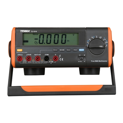
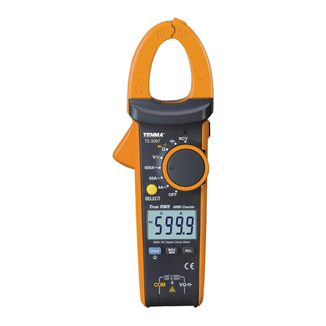
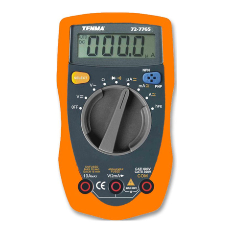
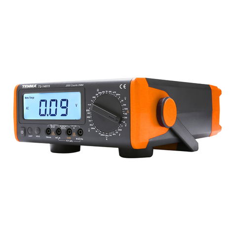
Tenma 72-3530 User manual

1
Industrial True RMS Digital
Multimeter
Model: 72-3530

2
CONTENTS
Page Number Details
2 What’s Included
3 Important Safety Information
3 Product Overview
4 Display
5 Function Selection & Buttons
5 Buttons
7 Measuring
7Measuring AC/DC Voltage
8 Measuring Resistance/Conductivity
9 Measuring Circuit Switching
9Diode Test
9 Measuring Capacitance
10 Measuring Frequency/Duty Ratio
10 Measuring Temperature
11 Measuring AC/DC
11 60A/600A ACA/DCA External Input Current Calipers Measurement
12 Non-contact AC Voltage Sensing
12 Square-wave Output
13 Other Functions
14 Technical Specications
14 Measurement of DC Voltage
14 Measurement of AC Voltage
15 Measurement of DC Current
15 Measurement of AC Current
16 Measurement of Resistance/Conductance
16 Measurement of Capacitance
17 Measurement of Frequency/Duty Ratio Cycle
18 Measurement of Temperature
18 Maintenance and Repair
WHAT’S INCLUDED
• Probe
• Point K-type thermocouple
• Lithium battery charger
• USB cable
• User manual

3
IMPORTANT SAFETY INFORMATION
• When using electrical appliances basic safety precautions should always be
followed.
• Before use, check the insulation layer of the probe, which should be kept intact
and without damage.
•There are no user-serviceable parts in this product. Refer all servicing to qualied
personnel.
• When the low battery symbol is displayed on the LCD, replace the battery
immediately to ensure measurements are precise.
• The function range switch must be placed at the correct measuring location.
• Signals detected are not allowed to exceed the limit value so as to prevent electric
shock and instrument damage.
• Gears of range switch are not permitted to change during measuring, in order to
help prevent electric shock and instrument damage.
• After each measurement is completed, it is necessary to disconnect the probe
from the circuit under test.
• Therefore, once measurement is complete, turn off the power supply and
disconnect the probe and circuit under test.
• When measuring voltage higher than DC 30V or AC 30Vrms, be careful when
using the instrument in order to avoid electric shock.
• Do not use the instrument at high temperatures or humidity.
• Do not store the instrument in a damp or humid environment as moisture is likely
to make the Multimeter’s performance deteriorate.
• When cleaning, use a damp cloth and a mild detergent to clean the instrument’s
outer case.
• Do not use any chemicals, abrasives or solvents that could damage the
instrument.
PRODUCT OVERVIEW
1. Shell 5. Range knob switch
2. Display 6. Input terminal for
measuring
3/4/7. Function keys 8. Alarm luminous diode
9. USB cable/bluetooth interface/NCV sensing
terminal
• 2 • " • ,
�o

4
Symbol Specication
Data recall
Data storage
Data hold
LoZ AC low impedance
Negative value
VFC Measuring of voltage to frequency converter
Alarm for high voltage
Circuit on-off measurement
Automatic shutdown
Auto Automatic range
Peak Peak measuring
MIN/AVG/MAX Prompt for measuring minimum/average/maximum value
AC/DC AC/DC measurement
∆Relative measuring
mV, V Voltage unit: millivolt and volt
µA, mA, A Current: Microamp, milliampere and ampere
Ω, kΩ, MΩ Resistance unit: Ohm, kilohm and megohm
nF, µF, mF Capacitance unit: nanofarad, microfarad and millifarad
Hz, kHz, MHz Frequency unit: Hz, kHz, and MHz
mS Period unit: millisecond
%Duty ratio or % (4-20mA) measurement unit
AC AC
nS Conductivity unit: nano-siemens
NCV Non-contact AC voltage sensing
°C / °F Celsius or Fahrenheit
Undervoltage of battery in the machine
Interface output
Measuring value for main display
Measuring value for auxiliary display
XXXX Auxiliary display: Storage no. and setting value
H XX: XX Auxiliary display: hour XX: XX timing value
Simulated pointer
DISPLAY
RCL
STO
7
�
0 •

5
FUNCTION SELECTION & BUTTONS
Function Knob Description
V~ V AC/DC Voltage measurement
LoZ AC low impedance voltage measurement
ΩResistance measurement
nS Conductivity measurement
Diode PN junction voltage measurement
Circuit on-off measurement
Capacitance measurement
Hz Frequency measurement
%Duty ratio measurement
% (4-20mA) For measurement on (4-20mA) current transducer only
°C °F Temperature measurement
µA~ mA~ 10A~ AC/DC measurement
AC+DC (AC + DC) measurement
600A ACA/DCA current calipers measurement
Output Square-wave output measurement
NCV Non-contact AC voltage sensing
Built-in lithium battery charging gear
OFF Power supply is off
BUTTONS
RANGE button
• Press to switch from automatic to manual range (the “Auto” prompt will disappear
from the LCD).
• A single press results in one gear of range upwards.
• After reaching the highest gear of the range, press to jump to the lowest gear of
the range and circulate in sequence.
• Press and hold the button for more than 2 seconds or rotate for switchover and it
will exit the mode of manual range.
STORE button
•Press the button to save a piece of data and the LCD will ash “ ”.
• Press and hold the button to enter the automatic storage setting menu.
• In the automatic storage setting menu, when the auxiliary display shows “SET.1”, it
is advised to set the interval for automatic storage (1~240) in the unit of seconds.
• Press HOLD to exit the setting.
• Press SELECT to enter the next interface and the auxiliary display shows “SET.2”.
It is advised to set the duration for automatic storage in the unit of minutes.
• Short press HOLD to return to SET.1 and press the SELECT button to start the
function of automatic recording based on the parameters set.
STO
*

6
• In automatic recording, press the HOLD/Esc button to exit Automatic Storage.
RECALL button
• Press the button to enter Recall Mode and the LCD will display “ ”.
• In Recall Mode, the auxiliary display shows the number for current data.
• Short press the REL or HZ% button to rapidly recall one piece of data forwards or
backwards.
• Short press the RANGE and HOLD buttons to delete current data and exit the
Recall Mode.
• If it is necessary to delete all of the data, do so in the system setting menu and
execute the “DEL” function.
MAX/AVG/MIN Peak hold button
• Press MAX MIN to enter the mode of Manual Range Recording. The function of
Automatic Shutdown is cancelled.
• The LCD will display “ ” and the auxiliary display will show ‘MAX’.
• Press the button and the LCD will display “ ” and the auxiliary display will show
‘AVG’.
• Press again and the LCD will display “ ” and the auxiliary display will show
‘MIN’.
• The sequence is MAX/AVG/MIN. Long press the MAX MIN button to exit the mode
of Data Recording.
• In AC voltage/current functional state, long press “Peak hold” to enter the function
of Peak Measurement. The LCD will display ‘Peak’.
• Short press it to independently switch between P-Max and P-Min modes. Long
press the “Peak hold” button to exit the function of peak measurement (the
response time is about 1mS).
HOLD/ button of data-hold/backlight
• Press the HOLD button and the displayed value will be locked and retained and
the display will show “ ”.
• Press again and the locking will be alleviated, entering the mode of General
Measuring.
• Press and hold the button to turn off or on the backlight and fast switch
between three kinds of backlight luminance.
/REL button of direction selection/relative measurement
• Press REL to automatically enter the mode of Manual Range for Relative
Measurement.
• Take the current displayed value as a reference value.
• Then press again to make the difference between the measured value and
reference value display on the main display.
• Press again to re-select current original data as a reference value.
•Press and hold the button to exit REL mode (applies to V , Ω, I , °C/°F and ).
Hz/%/ /Setup: button of frequency, duty ratio/direction selection/setting
• Press Hz% to make the frequency/duty ratio switch (applies to V~, I~, Hz% only).
• Long press the Setup button to enter the system setting menu.
• Setting items include “brt” (brightness) for backlight, “Usb” (USB) for
RCL
MAX
AVG
MIN
~ ~
7
communication on/off, “bEEp” (key beep) for buzzer switch on/off, “ALO” (ALO
time) for automatic light off, “APO” (APO time) for automatic power supply off,
“DEL” (format MEM) for memory formatting.
• Short press the arrow button to select an item and short press HOLD to exit the
setting menu.
• You can alter the parameters of the setting items through the RANGE or MAX MIN
buttons.
• If the parameter displayed on the auxiliary display is “YES”, the operation of
memory formatting will be executed by short pressing SELECT and all of the data
saved will be cleared.
SELECT/V.F.C - button of selection/measurement on voltage or current to
frequency conversion
• Press SELECT to choose the function.
• Press and hold V.F.C for two seconds in AC voltage mode and the LCD will display
“V.F.C”.
• It will be allowed to enter the mode of V.F.C measurement on voltage to frequency
conversion.
• Press and hold the button again and it will exit the mode of V.F.C measurement.
• In mV gear, press and hold SELECT to enter or exit the function of temperature
measurement.
• In µA gear, press and hold SELECT to enter or exit % (4-20mA).
MEASURING
• Before measuring, check the built-in battery.
• If the low battery symbol is showing on the LCD, then change the battery
immediately or charge before use.
• Watch out for the ! symbol beside the probe socket, which warns you of not
exceeding the indicated gure for voltage or current under test.
MEASURING AC/DC VOLTAGE
• The AC measuring displayed value is the true virtual value. During in-circuit
measurement, press the Hz/% button to select the mode of Measurement on
Frequency/Duty Ratio for the auxiliary display.
• In the DC voltage function gear, press SELECT to choose the mode of AC and DC
measurement.
• Press the Hz/% button and the auxiliary display will show AC/DC/Hz values in
order and the AC and DC value will be on the main display.
Caution
•If the input impedance of the instrument, which is about 10MΩ, is higher than the
load, it will cause an error in measurements of high-impedance circuits.
• Mostly, if a circuit is lower than 10k, errors can be ignored (0.1% or lower).
• Do not input voltage higher than 1,000Vrms. It is possible to measure higher
voltage, but it is very likely to damage the instrument.
•It’s recommended to test a known voltage before use in order to conrm that the
product is functioning correctly.

8
MEASURING RESISTANCE/CONDUCTIVITY
•When measuring ultra-high resistance, higher than 40MΩ, it is advised to use nS
range to measure its conductivity G: G=1/R (Ω). The unit Siemens (S)=10 9/R (Ω).
The unit is (nS).
• By virtue of the function of resistance measuring, it is allowed to make self-checks
on built-in fuses.
• Open circuit voltage is about 1V.
Caution
• If the resistance under test is an open circuit, or the resistance is beyond the
maximum range of the instrument, it will display “OL” on the LCD.
• When measuring in-circuit resistance, turn off all the power to the circuit under test
and discharge the residual electric charge in the capacitor before measuring, in
order to guarantee correct findings.
•In low-resistance measuring, the probe will result in an error of 0.1Ω-0.2Ω.
• In order to acquire an accurate reading, it is necessary to short-circuit the probe
and adopt Relative Measuring mode to ensure measuring precision.
•If probe resistance is higher than 0.5Ω in short circuit, it’s necessary to check
whether the probe is loose or if there is any other reason.
• When measuring high resistance, it is likely to take a couple of measurements
before the reading is stable. This is normal for measuring high resistance.
• It is not allowed to input voltage higher than DC 30V or AC 30V in order to prevent
personal injury.

9
MEASURING CIRCUIT SWITCHING
• If resistance between two terminals
measured is higher than 100Ω, it shall
be deemed as open circuit and the
buzzer will not sound.
• If the resistance between the two
terminals measured is lower than
10Ω, it shall be deemed as sound
conductivity of a circuit and the buzzer
will produce a constant sound.
Caution
• While inspecting in-circuit circuit
switching, it is necessary to cut off the
power supply to the circuit under test
and discharge residual electric charge
in the capacitor before measuring.
• Do not input voltage higher than DC
30V or AC 30V to prevent personal
injury.
DIODE TEST
• The range of test voltage for diode is
about 0-3V.
• The auxiliary display shows “diod”.
Caution
• If the diode under test is in open circuit
or reverse polarity, it will display “OL”.
In terms of silicon PN junction, 500-
800mV shall be generally conrmed as
normal value.
• When measuring in-circuit mode, it is
necessary to cut off all the power to
the circuit under test and discharge
residual electric charge in the capacitor
before measuring.
• Do not input voltage higher than DC
30V or AC 30V in order to prevent
personal injury.
MEASURING CAPACITANCE
•When there is no input, the instrument will display a xed reading, which is the
inherent capacitance of the instrument.
• When measuring capacitance in small-range gear, the inherent value must be
deducted from the measured value to guarantee precise measurements.
• Therefore it is allowed to utilize the function of Relative Measuring of the

10
instrument to make automatic
deduction, facilitating measuring
reading.
Caution
• If metered capacitance is in short
circuit, or capacitance is beyond the
maximum range of the instrument, the
LCD will display “OL”.
• When measuring large bulk
capacitance it is normal to take a few
seconds to measure.
• Before measuring, discharge all the
residual electric charge in capacitance,
particularly important for high-voltage
capacitance, preventing damage to the
meter and personal injury.
MEASURING FREQUENCY/DUTY RATIO
• In the gear of frequency measurement,
press the Hz% button to select the
mode of period for auxiliary display/
duty ratio measurement.
Caution
• Do not input voltage higher than DC
30V or AC 30V in order to prevent
personal injury.
MEASURING TEMPERATURE
• Press and hold SELECT in mV gear
to enter or exit the temperature
measurement function.
• Press SELECT under the temperature
measurement function to switch the
display between °C and °F.
• Temperature sensor: applicable to the
K-type thermocouple only.
• Boot up to display “OL” and plug in
the K-type temperature sensor to the
meter.
Caution
•The K-type thermocouple congured in
accessories is applicable to measuring
temperatures below 230°C/446°F only.

11
MEASURING AC/DC
• When measuring online AC, press the
Hz% button to select the auxiliary display
frequency/duty ratio measuring mode.
• Press SELECT to select the AC + DC
measuring mode and the “AC+DC” value
will be shown on the main display.
• When pressing the Hz% button, the
status on the auxiliary display is AC
component/DC component/frequency in
sequence.
• Press and hold SELECT in mA function
range to access the the % (4-20mA)
measuring function. The percentile
calibration of measured current will be
displayed: 4mA for 0%, 20mA for 100%.
Caution
• Before the instrument is connected in series to the circuit to be tested, cut off the
power supply to the circuit.
• When measuring, use the correct input terminal and function gear. In case of an
inability to estimate current magnitude, it is advised to start measuring from high-
gear range.
• The fuse is set inside 10A and mA/µA input jack. Ensure you do not parallel
connect the probe test pin to any circuit, in particular the power supply terminal, or
it will damage the instrument and personal safety will be at risk.
• In order for safe utilization, when the metered current is higher than 5A, each
measuring time will be less than 10 seconds and the interval will be more than 15
minutes.
60A/600A ACA/DCA EXTERNAL INPUT CURRENT CALIPERS MEASUREMENT
• Press RANGE to change
the
60A/600A measurement
and press the SELECT
button to select the
mode of the ACA/DCA
function.
D
====
o== o
MAX MIN
SELECT

12
NON-CONTACT AC VOLTAGE SENSING
• When checking whether the AC voltage
or the electromagnetic eld exists in
sensing space, approach the front end
of the instrument to the metered object
for sensing detection.
• If the analogue capacity of sensing
AC voltage is lower than or equal to
critical voltage V1, the main display will
show “EF”. If it is higher than the critical
voltage V1, the main display will display
the transverse section of “-”.
• Five sections of “- -” are set based on
the section voltage Vd, with a buzzing
sound stimulated in different tempos
so as to distinguish the magnitude of
sensing voltage. The red light will ash
on top of the instrument.
Caution
• When the range switch is set at the gear of “NCV”, no probe will be required for
sensing.
•If the electric eld voltage is greater than AC 100V, the instrument will let out
acousto-optic prompts (distance ≤10mm).
• If it is greater than 50mm, there will be no sound.
SQUARE-WAVE OUTPUT
• Long press SELECT to enter or exit
the square-wave output interface.
• Square-wave frequency output can
be selected with buttons RANGE and
MAXMIN.
• Square-wave duty ratio % can be
selected with (REL) (Hz%).
• Square-wave output amplitude is
about 0.8Vp.
• Square-wave output cycle/duty ratio is
1%-100%.
D
====
LIGHT(2S)
o o
D
0 o o 0
LIGHT(2S)

13
OTHER FUNCTIONS
Automatic Shutdown
• If the knob switches and buttons are not operated within the set shutdown time (5-
30 minutes), the instrument will automatically shutdown to save energy.
• In the state of automatic shutdown, press any button or turn the knob switch and it
will automatically wake up.
• From one minute before the automatic shutdown countdown, the APO sign will
icker.
• If the “BEEP” is set as “ON”, the buzzer will make three short “beep” warnings,
when counting down, for 40, 20 and 10 seconds. It will make one “beep” warning
in Sleep mode.
•Duing the icker of the APO sign, short press any button to cancel automatic
shutdown with no response to the original functions or buttons.
• In normal operation mode, access the Setup menu to cancel the automatic
shutdown function (APO TIME: OFF) and the character of APO on the LCD screen
will disappear automatically.
Buzzer
• Press any button switch in the mode of BEEP ON and if the button with the
corresponding function works, the buzzer will sound.
• In normal operation mode, it makes one “beep” sound if the button operation is
valid and two “beeps” if it is invalid.
• The “beep” of a button can be enabled or disabled in the Setup menu.
Low Voltage Detection
• If the internal VDD is lower than 7.3V, the low battery symbol will be displayed.
Charge the internal lithium battery to ensure that measurements are precise.
• If the low battery current is detected by the instrument it will be forced into Sleep
mode.
Charging the Internal Lithium Battery
Caution
• If the lead disconnects or the battery fails to
charge, a consecutive red/green ashing light
will be emitted by the indicator on top.
==
•
•
Connect the charging adaptor, as shown
(right).
When charging, a red indicator alert will be
emitted on top of the instrument, which turns
green when the charging reaches the full value
and the instrument will automatically cut off
from charging.

14
TECHNICAL SPECIFICATIONS
Accuracy is guaranteed for one year.
Ambient temperature: 23°C ± 5°C (73.4°F ± 9°F), relative humidity ≤75%.
Caution
•For accuracy, the temperature conditions should be controlled between 18°C and
28°C, while the uctuation range of the ambient temperature should be stabilised
within ±1°C.
•If the temperature is lower than 18°C or greater than 28°C, the additional
temperature coefcient error shall be 0.1 x (specied accuracy)/°C.
•If the change in ambient temperature is within ± 5°C, the accuracy is applied after
2 hours. Upon the completion of battery charging, the accuracy is also applied
after 2 hours.
MEASUREMENT OF DC VOLTAGE
Range Resolution
Accuracy ± (a% of reading + b counts)
DC Frequency
response 45Hz-1kHz >1kHz-20kHz
600.00mV 10µV
± (0.025%
+ 5) AC+DC ±(1.2% + 40) ± (6.0% + 40)6.0000V 100µV
60.000V 1mV
600.00V 10mV ± (0.03% + 5) Undened
1000.0V 100mV ± (0.03% + 5)
Input Impedance
•Range ≥ 1GΩ, input impedance for other ranges is 10MΩ.
•AC+DC, the specications are dened for signal input > 10% of range.
MEASUREMENT OF AC VOLTAGE
Range Resolution
Accuracy ± (a% of reading + b counts)
45Hz-1kHz >1kHz-
10kHz
>10kHz-
20kHz
>20kHz-
100kHz
600.00mV 10µV
± (0.4% +
40)
±(5.0% + 40) ±(5.5% + 40) ±(8.0% + 40)
6.0000V 100µV ±(1.2% + 40) ±(3.0% + 40) ±(8.0% + 40)
60.000V 1mV ±(1.2% + 40) ±(3.0% + 40) ±(6.0% + 40)
600.00V 10mV ±(3.0% + 40)
Undened
1000.0V 100mV ± (0.6% +
40) ±(3.5% + 40)
LoZ /
1000~V 0.1V ± (2% + 40)
V.F.C
600V/1000V 0.01V/0.1V ± (4% + 10) frequency response: 45 ~ 400Hz

15
• Input impedance is about 10MΩ.
• Display: true virtual value; range of accuracy guarantee: 10-100% of range (the
1000V range is 20~100%), it is allowed to have residual readings < 50 digits in
short circuit.
• AC wave peak factor can reach 3.0 in full-range value (excluding 750V range,
which is 1.5 in full-range value).
• Non-sinusoidal waveform: the accuracy will be increased by 3.0% if the wave peak
factor is within 1.0-2.0.
• The accuracy will be increased by 5.0% if the wave peak factor is within 2.0-2.5.
• The accuracy will be increased by 7.0% if the wave peak factor is within 2.5-3.0.
MEASUREMENT OF DC CURRENT
Range Resolution
Accuracy ± (a% of reading + b counts)
DC Frequency
response
>10kHz-
20kHz
>20kHz-
100kHz
600.00µA 0.01µA ±(0.25% + 20)
AC+DC
±(1.5% + 20) ±(2% + 40)
6000.0µA 0.1µA ±(0.25% + 2) ±(1.5% + 20) ±(2% + 40)
60.000mA 1µA ±(0.15% + 10) ±(1.5% + 20) ±(2% + 40)
600.00mA 10µA ±(0.15% + 10) ±(1.5% + 20) ±(3% + 40)
6.0000A 100µA ±(0.5% + 10) ±(2.0% + 20) ±(6% + 40)
10.000A 1mA ±(0.5% + 2) ±(1.5% + 10) ±(5% + 40)
% (4-20mA) 0.01% ±(0.5% + 2)
• AC+DC, the specications are dened for signal input > 10% of range.
MEASUREMENT OF AC CURRENT
Range Resolution Accuracy ± (a% of reading + b counts)
45Hz-1kHz >1kHz-20kHz >20kHz-100kHz
600.00µA 0.01µA ±(0.75% + 20) ±(1.2% + 40) ±(6.0% + 40)
6000.0µA 0.1µA ±(0.75% + 20) ±(1.2% + 40) ±(3.0% + 40)
60.000mA 1µA ±(0.75% + 20) ±(1.2% + 40) ±(9.0% + 40)
600.00mA 10µA ±(0.75% + 20) ±(1.5% + 10) ±(4.0% + 40)
6.0000A 100µA ±(1.5% + 20) ±(6.0% + 40) Undened
10.000A 1mA ±(1.5% + 5) ±(5.0% + 10)
• Display: true virtual value.
• Range of accuracy guarantee: 10-100% of range. It is allowed to have residual
readings < 50 digits in short circuit.
• AC wave peak factor can reach 3.0 in full-range value.
• Non-sinusoidal waveform: the accuracy will be increased by 3.0% if the wave peak
factor is within 1.0-2.0.
• The accuracy will be increased by 5.0% if the wave peak factor is within 2.0-2.5.
• The accuracy will be increased by 7.0% if the wave peak factor is within 2.5-3.0.

16
MEASUREMENT OF RESISTANCE/CONDUCTANCE
Range Resolution Accuracy ± (a% of reading + b counts)
600.00Ω 0.01Ω ± (0.05% + 10)
6.0000kΩ 0.1Ω ± (0.05% + 2)
60.000kΩ 1Ω ± (0.05% + 2)
600.00kΩ 10Ω ± (0.05% + 2)
6.0000MΩ 100Ω ± (0.15% + 5)
60.000MΩ 1kΩ ± (3% + 2)
60.00nS 0.01nS ± (1% + 10)
MEASUREMENT OF CAPACITANCE
Range Resolution Accuracy ± (a% of reading + b counts)
6.000nF 1pF ± (3.0% + 30)
60.00nF~600.0µF 10pF~100nF ± (2.5% +5)
6.000mF~60.00mF 1µF~10µF ± 10%
MEASUREMENT OF FREQUENCY/DUTY RATIO/CYCLE
Range Resolution Accuracy ± (a% of reading + b
counts)
60.000Hz~10.000MHz 0.001Hz~0.001MHz ± (0.01% + 5)
1.0%~99.0% 0.1% ± (3.0% +40)
100.0mS~0.100µS 0.1mS~0.001µS ± (0.1% + 5)
• Input range a:
≤100kHz: 500mVrms ≤ a ≤ 30Vrms
>100kHz-1MHz: 600mVrms ≤ a ≤ 30Vrms
>1MHz: 1Vrms ≤ a ≤ 30Vrms
•Duty ratio % is applicable to measuring ≤ 100kHz only.
• During AC voltage or AC current measuring, when frequency or duty ratio is
required to be read online, the following requirements must be met:
- Frequency response: ≤ 100kHz
- AC voltage: input range for 400.00mV or 600mV ≥ range x 10%
input range for 4.000V/40.000V/400.00V ≥ range x 10%
input range for 6.0000V/60.000V/600.00V ≥ range x 10%
input range for 1000.0V ≥ range x 30%
- AC current: input range for 4000.0µA/400.00mA ≥ range x 10%
input range for 400.00µA/40.000mA/4.0000A ≥ range x 10%
input range for 6000.0µA/600.00mA ≥ range x 10%
input range for 600.00µA/60.000mA/6.0000A ≥ range x 10%
input range for 10.000A ≥ range x 30%.

17
MEASUREMENT OF TEMPERATURE
Range Resolution Accuracy
°C -40~1000°C
-40~0°C
0.1°C
± (2% + 3°C)
>0~100°C ± (1% + 3°C)
>100~1000°C ± (2.5%)
°F -40~1832°F
-40~32°F
0.1F
± (2.4% + 5°F)
>32~212°F ± (1.5% + 5°F)
>212~1832°F ± (2.5% + 5°F)
Caution
Point K-type thermocouple congured in accessory is applicable to measuring
temperature below 230°C/446°F only.
MAINTENANCE & REPAIR
• Before opening the rear of the instrument, turn the power off and ensure the probe
is away from the terminal and circuit under test.
• Use a damp cloth and a mild detergent to clean the outer shell of the instrument.
• Do not use any chemicals, abrasives or solvents that could damage the
instrument.
•In the case of any abnormalities with the instrument, refer all servicing to qualied
personnel.
•When the battery is low, connect the power adaptor for charging (DC 10V, 500mA).
Made in China. www.premierfarnell.com
V.1.0
INFORMATION ON WASTE DISPOSAL FOR CONSUMERS OF
ELECTRICAL & ELECTRONIC EQUIPMENT.
This symbol indicate that separate collection of Waste Electrical and Electronic
Equipment (WEEE) or waste batteries is required. Do not dispose of these items with
general household waste. Separate for the treatment, recovery and recycling of the
materials used. Waste batteries can be returned to any waste battery recycling point
which are provided by most battery retailers. Contact your local authority for details of
the battery and WEEE recycling schemes available in your area.
Table of contents
Other Tenma Multimeter manuals

Tenma
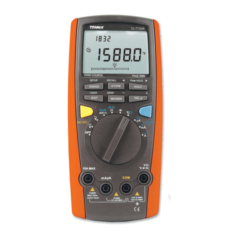
Tenma 72-7730A User manual

Tenma
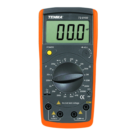
Tenma 72-8150 User manual

Tenma
Tenma TEN01061 User manual

Tenma
Tenma 72-7780 User manual

Tenma
Tenma 72-14615 User manual

Tenma
Tenma 72-10390A User manual

Tenma
Tenma 72-8495 User manual

Tenma
Tenma 72-7765A User manual

Tenma
Tenma 72-7228 User manual

Tenma
Tenma 72-8155 User manual