SpaGuts SG101-15UP-S User manual

UNIVERSAL INLINE
Hydromassage Bath Heater
INSTALLATION INSTRUCTIONS
CARTON CONTENTS:
A - One (1) Whirlpool Bath Heater
B - Two (2) 1.5” X 0.75” tailpieces *
C - Two (2) 1.5” X 1” tailpieces
D - Two (2) 1.5” X 1.5” tailpieces
E - Two (2) 2.0” X 2.0” tailpieces **
F - Two (2) heater gaskets
G - One (1) #8AWG bonding wire
*Not included with vacuum models
**Only this set of tailpieces with PH301-15UP/V
This Manual Covers:
Fig. 1
A
B
C
D
F
G
PRESSURE MODELS
5 1/2” Models
SG101-15UP-S - 120V, 1500W
7” Models
SG101-15UP - 120V, 1500W
SG101-10UP - 120V, 1000W
SG101-65UP - 120V, 650W
SG301-15UP - 120V, 1500W
SG203-20UP - 240V, 2000W
VACUUM MODELS
5 1/2” Models
SG101-15UV-S - 120V, 1500W
7” Models
SG101-15UV - 120V, 1500W
SG101-10UV - 120V, 1000W
SG101-65UV - 120V, 650W
SG301-15UV - 120V, 1500W
SG203-20UV - 240V, 2000W
E
Designed to maintain bath water temperature and is not meant to heat water from cool or cold.

INSTRUCTIONS PERTAINING TO RISK OF FIRE, ELECTRICAL SHOCK OR INJURY TO
PERSON
WARNING - When using this unit, basic precautions should always be followed, including the
following:
1. READ AND FOLLOW ALL INSTRUCTIONS
2. The heater must be connected only to a supply circuit that is protected by a ground-fault-circuit-
interrupter (GFCI). Such a GFCI should be provided by the installer and should be tested on a
routine basis. To test the GFCI, push the test button. The GFCI should interupt power. Push the
reset button. The Power should be restored. If the GFCI fails to operate in this manner, the GFCI is
defective. If the GFCI interrupts power to the heater without the test button being pushed, a
ground current is flowing, indicating the possibility of an electrical shock. Do not use this
hydromassage bathtub. Disconnect this hydromassage bathtub and have the problem corrected by
a qualified service representative before using.
3. SAVE THESE INSTRUCTIONS
IMPORTANT SAFETY INSTRUCTIONS
Prolonged immersion in hot water may induce hyperthermia. Causes, symptoms, and effects of
hyperthermia:
Hyperthermia occurs when the internal temperature of the body reaches a level several degrees
above the normal body temperature of 98.6°F. The symptoms of hyperthermia include an increase in
the internal temperature of the body, dizziness, lethargy, drowsiness, and fainting. The effects of
hyperthermia include:
A) Failure to perceive heat,
B) Failure to recognize the need to exit the bathtub,
C) Unawareness of impending hazard,
D) Fetal damage in pregnant women,
E) Physical inability to exit the bathtub, and
F) Unconsciousness resulting in the danger of drowning.
WARNING - The use of alcohol, drugs, or medication can greatly increase the risk of fatal
hyperthermia.
1

CONTENTS
GLOSSARY
2
SAFETY INSTRUCTIONS
CONTENTS & GLOSSARY
MODEL IDENTIFICATION
INSTALLATION INSTRUCTIONS (Heater Ready fitting Installed)
Pressure Installation
Vacuum Installation
INSTALLATION INSTRUCTIONS (No Heater Ready fitting)
Pressure Installation
Vacuum Installation
ELECTRICAL REQUIREMENTS
BONDING YOUR HEATER
TEST YOUR INSTALLATION
TROUBLESHOOTING
WARRANTY & INSTALLATION NOTES
TEMPLATE ILLUSTRATION
TEMPLATE CUTOUTS
1
2
3
5
6
7
9
11
12
13
14
15
16
17
Reading all instructions prior to beginning the installation of your Whirlpool Bath Heater
will ensure that you have:
A) Purchased the correct heater
B) Identified the best installation location
C) The necessary electrical connection has been provided
5 1/2” (-S)
7”
De-burr
Inline Heater
Heater Ready Fitting
Pump Union
PVC
Tailpiece
Tee Heater
“UP” Series
“UV” Series
Refers to Whirlpool Bath Heaters where stainless steel heater housing measures 5 1/2 inches from flat
sealing surface to flat sealing surface.
Refers to Whirlpool Bath Heaters where stainless steel heater housing measures 7 inches from flat sealing
surface to flat sealing surface.
Refers to removing excess plastic that may have built up during the cutting process.
A heater that can be installed directly inline in the existing plumbing system of a hydromassage bathtub.
Molded plastic heater blank assembly, provided for ease of aftermarket heater installation.
Refers to the plastic pieces used to join the bathtubs plumbing system to the hydromassage jet pump.
Refers to the plastic plumbing system of your hydromassage bathtub. This will be referred to during the
cutting and glueing procedures.
Refers to the threaded plastic pieces included with your heater that are glued to the hydromassage
bathtubs plumbing and allow the heater to be attached.
A heater that is just that, shaped like a “T”. These heaters connect directly to the pump of a
hydromassage bathtub.
Pressure - Refers to the “discharge” side of the pump. The water discharged from the pump supplies all of
the pressure fittings such as the hydromassage jets that eject water into the bathtub. Throughout these
instructions discharge will be referred to as “pressure”.
Vacuum - Refers to the “suction” side of the pump. The water that is pulled through the bathtubs suction
fitting is routed to the pump via the “vacuum” plumbing. Throughout these instructions suction will be
referred to as “vacuum”.
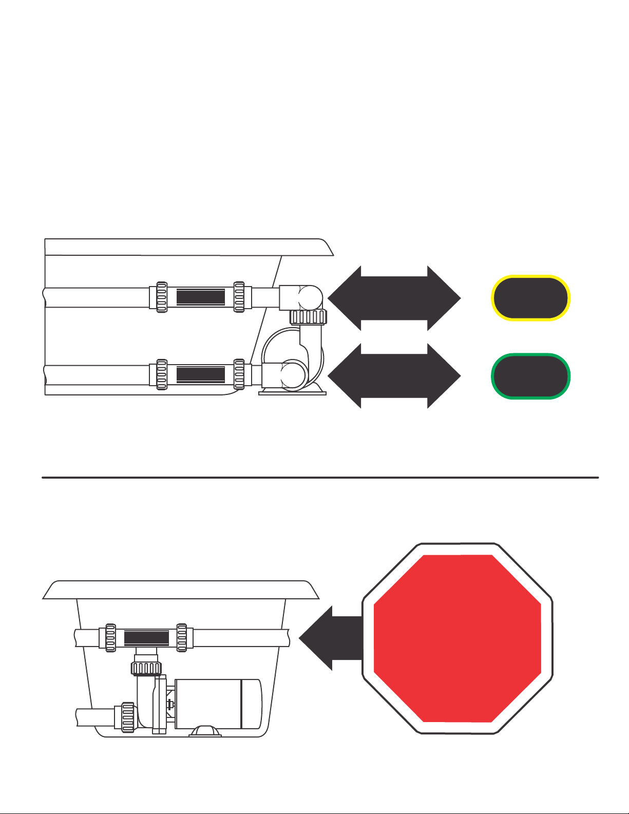
MODEL IDENTIFICATION
If your hydromassage bathtub has been equipped at the factory with a Heater Ready fitting, the
manufacturer has already chosen the best place for your Whirlpool Bath Heater to be installed. (See
figures 2 & 3 below for common heater location.) Note: these instructions do not cover the Tee
Style hydromassage bathtub heater.
Fig. 2
INLINE HEATER
TEE HEATER
3
VACUUM MODELS
PRESSURE MODELS HEATER READY
HEATER READY
HEATER READY
PROCEED
TO PAGE 5
Fig. 3
PROCEED
TO PAGE 6
!! STOP !!
These instructions do
not cover the Tee Style
heater - Arrange to
receive the proper
heater and refer to the
enclosed installation
instructions.
-UP SERIES
PRESSURE
-UV SERIES
VACUUM
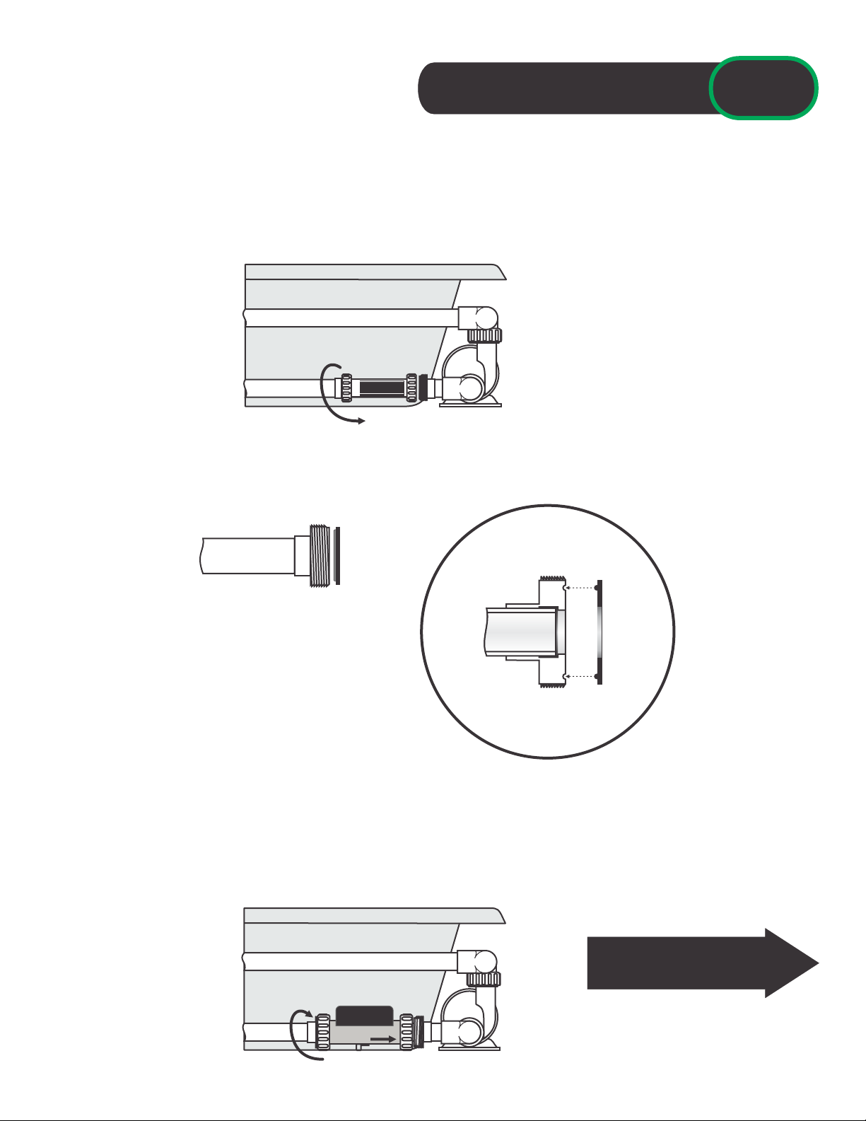
HEATER READY FITTING INSTALLED

CLEARANCE:
Your Whirlpool Bath Heater has been specifically
designed to be compact and easy to install. In
most cases there will be no interference installing
your hydromassage bathtub with the addition of a
Whirlpool Bath Heater. Prior to installing your
heater, consult manufacturers instructions
regarding bathtub installation clearance
requirements.
If your hydromassage bathtub did not come equipped with a Heater Ready fitting you will need to
choose an appropriate location to install the Whirlpool Bath Heater. Be sure you choose a location
that will be accessible if a need for service should arise. The model of Whirlpool Bath Heater
(pressure vs vacuum) is clearly marked on the outside of the carton. This will determine where the
heater is installed. (See figures 4-6 below for common heater location.)
PRESSURE MODELS
PRESSURE MODELS
VACUUM MODELS
PRESSURE MODELS
VACUUM MODELS
PRESSURE MODELS
INLINE-PRESSURE & VACUUM MODELS
INLINE PRESSURE HEATER
INLINE PRESSURE HEATER
4
Fig. 4
Fig. 5
Fig. 6
PROCEED
TO PAGE 7
PROCEED
TO PAGE 7
PROCEED
TO PAGE 7
PROCEED
TO PAGE 9
MODEL IDENTIFICATION
-UP SERIES
PRESSURE
-UP SERIES
PRESSURE
-UV SERIES
VACUUM
-UP SERIES
PRESSURE
NO HEATER READY FITTING
Fig. 7

5
PRESSURE INSTALLATION
1 - Power to the hydromassage bathtub must be turned OFF and all water must be drained
from the bathtub before proceeding.
2 - Loosen nuts and remove Heater Ready fitting and existing gaskets.
3 - Remove the new heater gaskets included with your Whirlpool Bath Heater and install them onto
the plumbing tailpieces, making sure the gasket ridge is seated in the tailpiece groove (see Fig.
9).
TAILPIECE GASKET
PLUMBING
4 - You are now ready to install the heater in the open space where the Heater Ready fitting was
located (ensure that the gaskets remain in place). Slide both heater nuts inward toward the
center of the heater to expose the mating surfaces of the heater housing. Slide the heater
carefully into place between the tailpieces and gaskets and hand-tighten heater nuts. If you use a
wrench be careful not to over-tighten, the nuts can crack.
Fig. 9
Fig. 10
Fig.8
HEATER READY ASSURE YOU ARE INSTALLING
A PRESSURE MODEL FOR THIS
LOCATION
IF THERE IS INSUFFICIENT
SPACE, THE HEATER MAY BE
ROTATED TO THE CONTROL
BOX DOWN POSITION.
CONTINUE ON TO PAGE 12
“BONDING YOUR HEATER”
-UP SERIES
PRESSURE Heater Ready Fitting Installed
6
VACUUM INSTALLATION
1 - Power to the hydromassage bathtub must be turned OFF and all water must be drained
from the bathtub before proceeding.
2 - Loosen nuts and remove Heater Ready fitting and existing gaskets.
3 - Remove the new heater gaskets included with your Whirlpool Bath Heater and install them onto
the plumbing tailpieces, making sure the gasket ridge is seated in the tailpiece groove (see Fig.
12).
TAILPIECE GASKET
PLUMBING
4 - You are now ready to install the heater in the open space where the Heater Ready fitting was
located (ensure that the gaskets remain in place). Slide both heater nuts inward toward the
center of the heater to expose the mating surfaces of the heater housing. Slide the heater
carefully into place between the tailpieces and gaskets and hand-tighten heater nuts. If you use a
wrench be careful not to over-tighten, the nuts can crack.
Fig. 12
Fig.13
Fig. 11
HEATER READY
ASSURE YOU ARE INSTALLING
A VACUUM MODEL FOR THIS
LOCATION
CONTINUE ON TO PAGE 12
“BONDING YOUR HEATER”
Heater Ready Fitting Installed -UV SERIES
VACUUM
1 - Power to the hydromassage bathtub must be turned OFF and all water must be drained
from the bathtub before proceeding.
2 - Locate the hydromassage jet pump and “pressure” plumbing in the system. Remember, the water
enters the pump through the front or “vacuum” side and exits through the top or “pressure” side.
Fig. 14
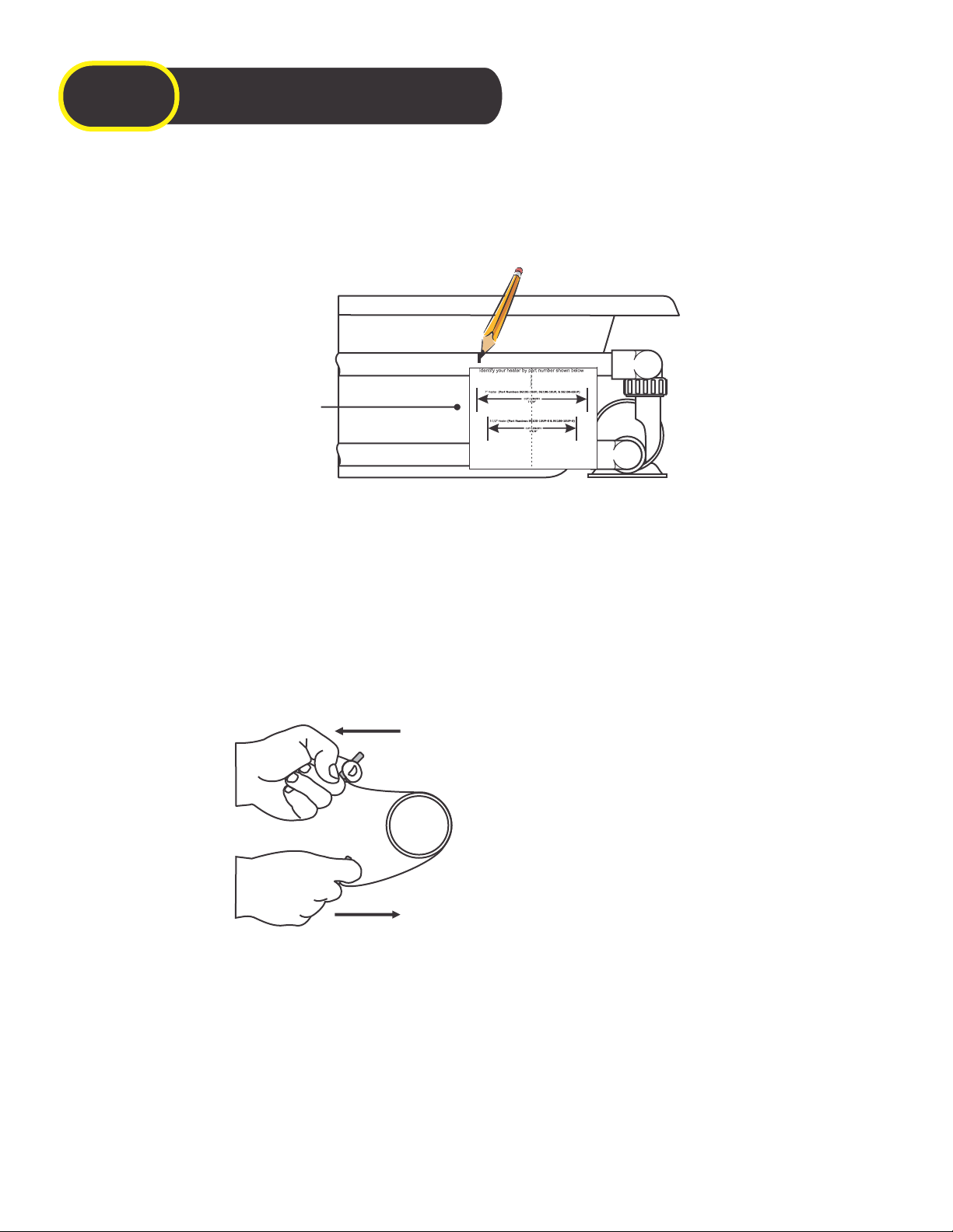
3 - Choose a location for your Whirlpool Bath Heater close to the hydromassage jet pump, ensuring
there is at least 2-1/2” of plumbing left on each side of the cuts to install the tailpieces. For
convenience, a template has been provided on the back page of this instruction booklet. Simply
detach, position against plumbing and mark according to plumbing size.
4 - Using a hacksaw, PVC cutter or a cable saw, cut the pipe at the marks made. If using a cable
saw, carefully line the saw blade up with the marks that were made in the previous step and
begin cutting using an alternating pulling/releasing motion (see Fig. 15). Once successfully cut
away, discard the detached portion of plumbing.
Fig. 15
7
PRESSURE INSTALLATION
-UP SERIES
PRESSURE No Heater Ready Fitting
Template located on
back page. Cut and
detach
-UP SERIES
PRESSURE
5 - De-burr the plumbing, clean outer surface of plumbing and prepare the surfaces for gluing.
6 - Your Whirlpool Bath Hetaer includes three (3) sets of tailpieces (1 set for 2” plumbing) to adapt
the heater to virtually any hydromassage bathtubs plumbing system. Dry fit the tail pieces to
determine which tailpieces adapt properly to your plumbing and discard the tailpieces that do not
fit.
Note: Let the saw blade do the
work, do not put excess pressure
on the plumbing. Have someone
else stabilize the plumbing while
you cut if needed.

7 - You are now ready to install the tailpieces onto the bathtub plumbing. Apply PVC glue to one end
of the plumbing. Spread glue evenly over a 1-1/4” area from the end of the cut. Quickly apply
glue to the inside socket of the tailpiece. Before the glue dries, slide the tailpiece onto the
plumbing with a slight twisting motion assuring it has reached the stop built into the tailpiece and
hold for 15-seconds to allow the glue to setup. Wipe away any excess glue and repeat the gluing
process on the second tailpiece. Once the glue has set, you should have approximately 7”
opening for part numbers: SG101-15UP, SG101-15UV, SG101-10UP, SG101-10UV, SG101-65UP,
SG101-65UV, SG301-15UP & SG301-15UV OR 5-1/2” opening for part numbers: SG101-15UP-S &
SG101-15UV-S (see Fig. 17) in order to install your Whirlpool Bath Heater.
Fig. 17
Fig. 16
8 - Remove two (2) heater gaskets included with your Whirlpool Bath Heater and install them onto
the plumbing tailpieces, making sure the gasket ridge is seated in the tailpiece groove (see Fig.
18).
TAILPIECE GASKET
PLUMBING
Fig. 18
PRESSURE INSTALLATION
(continued)
No Heater Ready Fitting -UP SERIES
PRESSURE
7”
OR
5-1/2”
9 - You are now ready to install the heater in the open space between the two (2) tailpieces (ensure
that the gaskets remain in place). Slide both heater nuts inward toward the center of the heater
to expose the mating surfaces of the heater housing. Slide the heater carefully into place
between the tailpieces and gaskets and hand-tighten heater nuts. If you use a wrench be careful
not to over-tighten, the nuts can crack.
Fig. 19
CONTINUE ON TO PAGE 12
“BONDING YOUR HEATER”
8
IF THERE IS INSUFFICIENT
SPACE, THE HEATER MAY BE
ROTATED TO THE CONTROL
BOX DOWN POSITION.

1 - Power to the hydromassage bathtub must be turned OFF and all water must be drained
from the bathtub before proceeding.
2 - Locate the hydromassage jet pump and “vacuum” plumbing in the system. Remember, the water
enters the pump through the front or “vacuum” side and exits through the top or “pressure” side.
Fig. 20
9
VACUUM INSTALLATION
No Heater Ready Fitting
CUT HERE
Template located on
back page. Cut and
detach
-UV SERIES
VACUUM
3 - Choose a location for your Whirlpool Bath Heater close to the hydromassage jet pump, ensuring
there is at least 2-1/2” of plumbing left on each side of the cuts to install the tailpieces. For
convenience, a template has been provided on the back page of this instruction booklet. Simply
detach, position against plumbing and mark according to plumbing size.
4 - Using a hacksaw, PVC cutter or a cable saw, cut the pipe at the marks made. If using a cable
saw, carefully line the saw blade up with the marks that were made in the previous step and
begin cutting using an alternating pulling/releasing motion (see Fig. 21). Once successfully cut
away, discard the detached portion of plumbing.
Fig. 21
5 - De-burr the plumbing, clean outer surface of plumbing and prepare the surfaces for gluing.
6 - Your Whirlpool Bath Heater includes three (3) sets of tailpieces (1 set for 2” plumbing) to adapt
the heater to virtually any hydromassage bathtubs plumbing system. Dry fit the tail pieces to
determine which tailpieces adapt properly to your plumbing and discard the tailpieces that do not
fit.
Note: Let the saw blade do the
work, do not put excess pressure
on the plumbing. Have someone
else stabilize the plumbing while
you cut if needed.

10
Fig. 23
Fig. 22
8 - Remove two (2) heater gaskets included with your Whirlpool Bath Heater and install them onto
the plumbing tailpieces, making sure the gasket ridge is seated in the tailpiece groove (see Fig.
24).
TAILPIECE GASKET
PLUMBING
Fig. 24
VACUUM INSTALLATION
(continued)
No Heater Ready Fitting
9 - You are now ready to install the heater in the open space between the two (2) tailpieces (ensure
that the gaskets remain in place). Slide both heater nuts inward toward the center of the heater
to expose the mating surfaces of the heater housing. Slide the heater carefully into place
between the tailpieces and gaskets and hand-tighten heater nuts. If you use a wrench be careful
not to over-tighten, the nuts can crack.
Fig. 25
CONTINUE ON TO PAGE 12
“BONDING YOUR HEATER”
-UV SERIES
VACUUM
7”
OR
5-1/2”
7 - You are now ready to install the tailpieces onto the bathtub plumbing. Apply PVC glue to one end
of the plumbing. Spread glue evenly over a 1-1/4” area from the end of the cut. Quickly apply
glue to the inside socket of the tailpiece. Before the glue dries, slide the tailpiece onto the
plumbing with a slight twisting motion assuring it has reached the stop built into the tailpiece and
hold for 15-seconds to allow the glue to setup. Wipe away any excess glue and repeat the gluing
process on the second tailpiece. Once the glue has set, you should have approximately 7”
opening for part numbers: SG101-15UP, SG101-15UV, SG101-10UP, SG101-10UV, SG101-65UP,
SG101-65UV, SG301-15UP & SG301-15UV OR 5-1/2” opening for part numbers: SG101-15UP-S &
SG101-15UV-S (see Fig. 23) in order to install your Whirlpool Bath Heater.
11
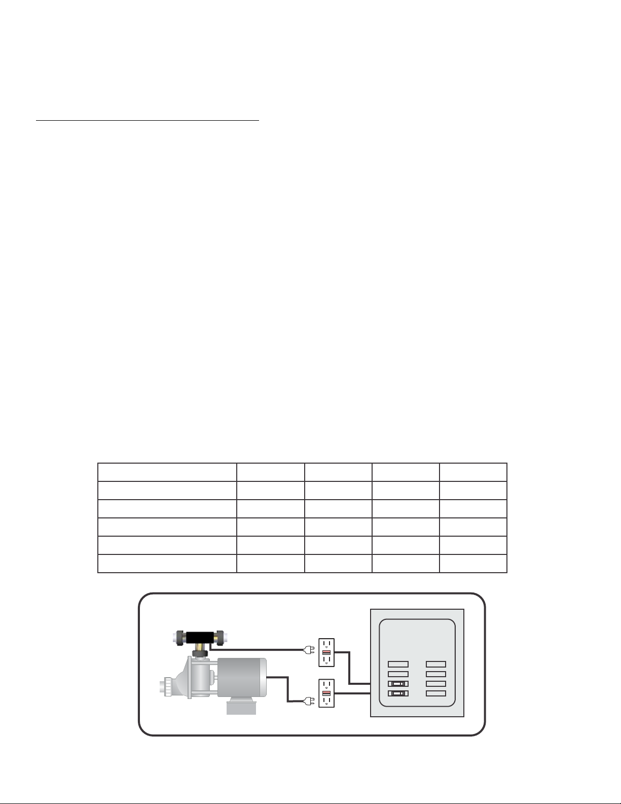
ELECTRICAL REQUIREMENTS
DEDICATED CIRCUIT INSTALLATION
A qualified and licensed electrician in accordance with the National Electric Code (NEC) Article 680,
Canadian Electric Code, and with any local codes must accomplish the electrical installation.
All connections must be made according to the electrical installation label on the outside of the control
box. Follow the instructions from the label if they are different than the instructions in this manual. If your
electrician is not absolutely sure how to connect your system correctly, call your local dealer. Any mistake
may be costly and void your equipment warranty.
The GFCI (Ground Fault Circuit Interrupter) is a mandatory electrical safety device required for all
hydromassage bathtubs as specified in the National Electrical Code Article 680-70.
Your bath equipment may require a DEDICATED CIRCUIT. This means no other appliances or lights
can be on this circuit. Refer to equipment data label for power supply requirements of your bath
heater.
Use copper conductors ONLY. The ground must be sized following the National Electric Code, Table
250-122.
For Power conductor size, refer to the National Electric Code Table 310-16.
SG101-15UV(-S)
SG101-15UP(-S)
12
12
15
15
YES
YES
YES
YES
MODELS
MAX
AMPS
CIRCUIT
BREAKER
GFCI
REQUIRED
BONDING
REQUIRED
NOTE: Read both the “Dedicated Circuit” and “Single Circuit” sections to determine the
electrical requirements of your heater before proceeding.
These models will most likely require a dedicated circuit due to their high power demand
and voltage requirements.
SG301-15UV
SG301-15UP
12
12
15
15
YES
YES
YES
YES
RESET
TEST
RESET
TEST
ELECTRICAL
PANEL
TWO (2) SINGLE CIRCUITS
15A / 115V OR 10A / 240V**
BRANCH CIRCUIT
15A / 115V OR 10A / 240V**
BRANCH CIRCUIT
SG203-20UV
8
10 YES YES
SG203-20UP
8
10 YES YES
**240V Heater cords do not have a Nema plug and require hard wiring of the unit.

12
1 - Prior to testing your installation for leaks, you must properly bond the Whirlpool Bath Heater to
the bonding system of your hydromassage bathtub. All Whirlpool Bath Heaters come equipped
with a bonding lug and 8AWG bonding wire specifically for this purpose. Refer to bathtub
manufacturers instructions to locate the bonding system. All electrical wiring and bonding must
be done as specified in Article 680, National Electric Code and your local Building Code.
8AWG Bonding Wire
(Included with your heater - *May Be on Bottom of Tube*)
To Bathtub
Bonding System
BONDING YOUR HEATER
Bonding Lug
Fig. 23
7” Inline Shown
SINGLE CIRCUIT INSTALLATION**
In certain cases you may be able to plug the heater and the pump into the same single circuit outlet.
This generally requires that one or both of the components have a very low amperage rating. See the
chart below to determine if your components are sized to allow this type of installation.
If your heater
amps are . . .
AND
AND
AND
THEN
THEN
THEN
Your pump amps
are less than. . .
10.6A
7.7A
3.5A
You can use a single
circuit this size
20A
20A
20A
5.4A
8.3A
12.5A
(650W)
(1000W)
(1500W)
ELECTRICAL
PANEL
ONE (1) SHARED CIRCUIT
RESET
TEST
15A / 115V OR 20A / 115V
BRANCH CIRCUIT
**Single circuit installation does not apply to 240V heaters.
13
8 - After allowing the glue joints to dry for 24-hours, a STATIC leak test must be performed. You can
accomplish this by SLOWLY filling the tub with COLD WATER until the water level is at least 2”
above the highest jet.
IMPROPER INSTALLATION OF THE WHIRLPOOL BATH HEATER CAN RESULT IN
WATER LEAKING FROM THE PLUMBING SYSTEM! WATER DAMAGE CAN OCCUR TO
SPACES BELOW OR ADJACENT TO THE HYDROMASSAGE BATHTUB.
Do not leave the tub unattended during the testing process and only fill the tub with enough
water to exceed the level of the hydromassage jets.
FILL THE TUB SLOWLY SO FILLING CAN BE STOPPED IF A LEAK IS DETECTED. DRAIN
THE TUB IMMEDIATELY IF A LEAK IS DETECTED AND CORRECT THE PROBLEM
BEFORE RETESTING.
9 - If no leaks were detected, a PRESSURE leak test must be performed. Perform this final
REQUIRED leak test by activating the hydromassage jet pump. Allow the system run for 15-20
minutes minimum. The cold water will allow you to verify that the “Heater On” indicator is
illuminated on your Whirlpool Bath Heater. If the light does not illuminate or if you encounter any
other problems, refer to the Troubleshooting section of these instructions.
IF NO LEAKS WERE DETECTED AND YOU HAVE VERIFIED THAT
YOUR WHIRLPOOL BATH HEATER IS FUNCTIONING PROPERLY,
CONGRATULATIONS, THE INSTALLATION OF YOUR WHIRLPOOL
BATH HEATER IS COMPLETE. YOU CAN NOW RELAX AND ENJOY
THE COMFORT YOU WILL EXPERIENCE IN YOUR HEATED
HYDROMASSAGE BATHTUB.
Fig. 24
TEST YOUR INSTALLATION

14
TROUBLESHOOTING
THERE ARE NO SERVICEABLE PARTS INSIDE HEATER - DO NOT OPEN
NOTHING WORKS!
Main Breaker is OFF - Set to On
GFCI Tripped - Press Reset
Power Cord not plugged in - Plug in power cord (if plugged in, is plug lit?)
HEATER “ON” LIGHT DOES NOT TURN ON
Overheat Protection Switch Tripped - Press to Reset
Power cord not plugged in - Plug in power cord (if plugged in, is plug lit?)
GFCI Tripped - Press Reset
No Power to Heater - Reset breaker at service panel
Pump Is Not Running - Activate hydromassage pump
Water Temperature Too High
HEATER “ON” LIGHT WILL NOT TURN OFF
Water Level Too Deep for Pressure Switch Setting - Lower Water Level
Pressure Switch Defective - Replace Heater
Heater Wiring Error - Replace Heater
OVERHEAT PROTECTION SWITCH TRIPPED
Water Blockage - Correct/Remove Blockage
Low Water Flow - Correct Problem
High-Limit Will Not Reset - Replace Heater
WATER LEAKS FROM CONTROL BOX
Defective Component - Replace Heater
GFCI TRIPS OCCASIONALLY
Lightning or Electrical Storm, Power Surge, Extremely Humid Conditions or Radio Frequency
Interference - Reset GFCI Note: Assure Heater is Properly Grounded and Bonded
Inspect Heater for Leaks or Moisture - Correct or Replace as Required
GFCI TRIPS REPEATEDLY
Defective Component - Replace Heater
CIRCUIT BREAKER TRIPS
Breaker Size Improper - Contact a qualified service technician
Heater Requires a DEDICATED Circuit - Assure No Other Appliances are on this Circuit
TEMPERATURE NOT REACHING COMFORT ZONE
Designed to maintain bath water temperature and is not meant to heat water from cool or cold.
TROUBLESHOOTING

15
INSTALLATION NOTES:
Installer/Electrician:
Address:
City: Zip:
Phone: Mobile:
Date:
Keep this information handy if there is a need for service in the future. The data label located on the outside of the heater control
box contains information that will be required if a need for service should arise.
WHIRLPOOL BATH HEATER TWO YEAR LIMITED WARRANTY
The manufacturer, warrants its Whirlpool Bathtub Heaters to be free from defects in material and
workmanship for a period of two (2) years from the date of manufacture.
Products determined to be defective within the warranty period will be repaired or replaced at the
manufacturer’s option with the following exclusions:
Products damaged or defective as a result of freezing, water chemistry, negligence, abuse,
misapplication, unauthorized modification, improper installation, wear and tear, chemical attack or
“acts of God” not controllable by the manufacturer. This warranty extends only to the original
purchaser for non commercial product usage.
The manufacturer is not responsible for consequential damages. All expenses relating to labor or
materials associated with access to, inspection, removal or reinstallation of the warrantable product is
bourn by the purchaser. The purchaser’s sole remedy will be the repair or replacement of the
manufacturer’s product.
Any products which are claimed to be defective must be shipped freight prepaid to the manufacturer
and the repaired or replaced product will be returned to the sender freight collect. When sent to the
manufacturer, the product must be accompanied by the sales receipt or other proof of the purchase
date as well as the sender’s name, mailing address, daytime phone number and any other
information relating to this claim.
Unless state law expressly provides otherwise, the manufacturer will only be responsible for repair or
replacement of any of its products that are found to be defective as provided above, and will not bear
the cost of any consequential damages. This warranty gives you specific legal rights, but you may
have other rights which vary from state to state.

16
Fig. A - Mark PVC cut area
Note: Identify your heater by part number
Fig. B - Mark PVC cut area
17
CUT HERE
CUT-LENGTH
7 5/8”
7” Heater
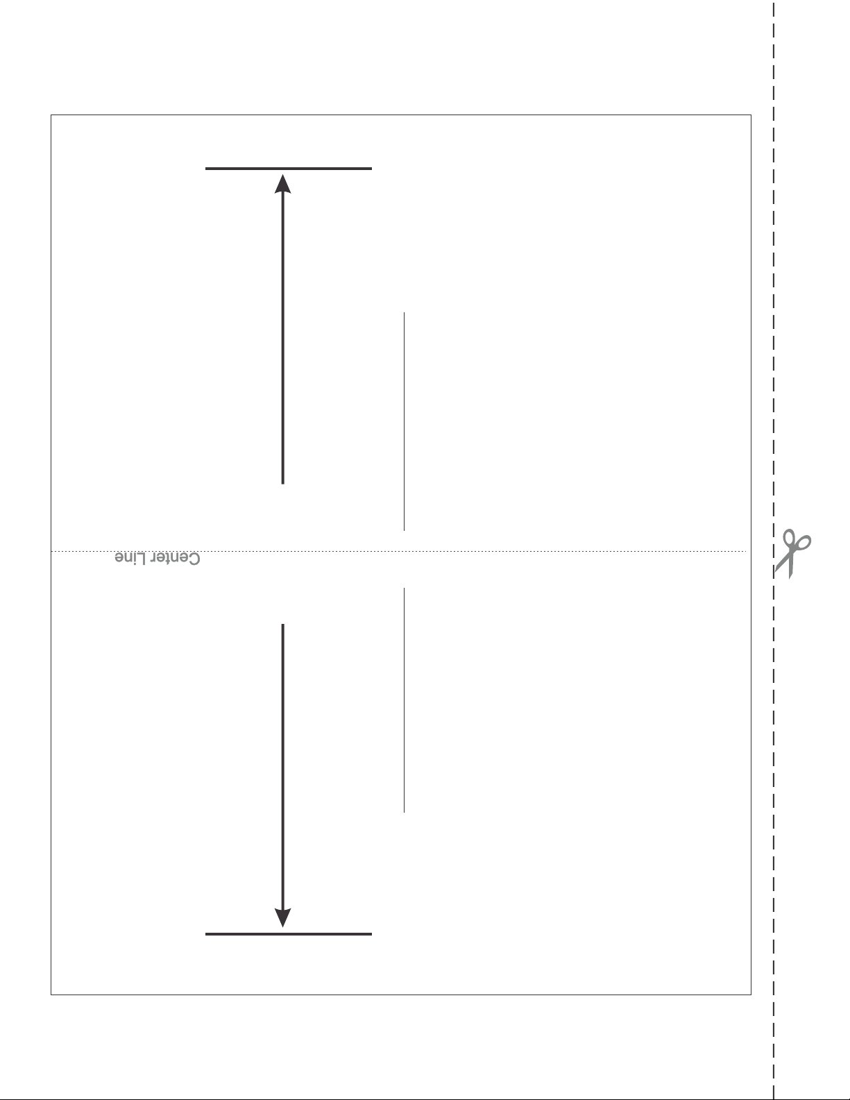
Use this template as a guide when making cuts during Whirlpool Bath
heater installation. Cut and detach from instructions.
! Determine the length of the heater
! Lay template on PVC plumbing (See page 16)
! Mark according to length of heaters
! Measure twice, cut once
Identify your heater by part number shown below
7” Models Pressure Models
SG101-15UP - 120V, 1500W
SG101-10UP - 120V, 1000W
SG101-65UP - 120V, 650W
SG301-15UP - 120V, 1500W
SG203-20UP - 240V, 2000W
7” Models Vacuum Models
SG101-15UV - 120V, 1500W
SG101-10UV - 120V, 1000W
SG101-65UV - 120V, 650W
SG301-15UV - 120V, 1500W
SG203-20UV - 240V, 2000W

18
CUT HERE
CUT-LENGTH
6 1/8”
5 1/2” Heater
Use this template as a guide when making cuts during Whirlpool Bath
heater installation. Cut and detach from instructions.
! Determine the length of the heater
! Lay template on PVC plumbing (See page 16)
! Mark according to length of heaters
! Measure twice, cut once
Identify your heater by part number shown below
5 1/2” Models Pressure Model
SG101-15UP-S - 120V, 1500W
5 1/2” Models Vacuum Model
SG101-15UV-S - 120V, 1500W

85-0049PH-Z REV.3 05/14
This manual suits for next models
11
Table of contents
Other SpaGuts Heater manuals

Popular Heater manuals by other brands


Empire
Empire RH-50-7 Installation instructions and owner's manual

Svan
Svan SVCA04CV instruction manual

LUCHT LHZ
LUCHT LHZ VPN Series Installation and operating instructions

Blyss
Blyss Ellesmere 3663602844822 quick start guide

Serene
Serene S6068 Sorroco Operation manual

Plen Air
Plen Air Infra Mini instruction manual