BE HK070-R Training manual

HK070-R / HK125-RW
User’s Manual &
Operating Instructions
CONSUMER: READ AND SAVE THESE INSTRUCTIONS
BPRG-400
GENERAL HAZARD WARNING:
READ AND UNDERSTAND ALL OF THE INSTRUCTIONS IN THIS MANUAL
BEFORE ASSEMBLING, STARTING, OR SERVICING THE HEATER. Be sure to comply with the
instructions and warnings provided with this heater. Failure to comply can result in fire or explosion
that can cause property loss, bodily injury, or loss of life. Only persons who can follow and
understand these instructions should operate or service this heater.
DANGER
NOT FOR USE IN RESIDENTIAL LIVING AREAS OR IN ENCLOSED SPACES
WITHOUT ADEQUATE VENTILATION. TO BE USED IN WELL VENTILATED
COMMERCIAL / INDUSTRIAL OCCUPANCIES. This is an unvented portable heater that uses
air (Oxygen) from within the area in which it is used. Failure to provide adequate combustion and
ventilation air will result in asphyxiation, carbon monoxide poisoning, bodily injury or death. Refer to
“Ventilation” on Page 7.
DANGER
This appliance shall be installed in accordance with the rules in force,
and used only in sufficiently ventilated space. Consult instructions before
installation and use of this appliance.
WARNING
OIL FIRED FORCED CONVECTION AIR HEATER
ORIGINAL INSTRUCTIONS
© 2019, BE Pressure Australia
Head Ofce
15 Hudson Place
Mulgrave NSW 2756, Sydney
HK070-R HK125-RW

NEVER LEAVE HEATER UNATTENDED WHILE BURNING OR WHILE
CONNECTED TO A POWER SOURCE
Oil Fired Radiant Heater User’s Manual
© 2019, BE Pressure Australia 1
Table Of Contents
SafetyInformation.............................................1-2
Features and Specications.................................3
HK070-R Assembly..............................................4
HK125-RWAssembly.......................................5-6
Ventilation............................................................7
Operation..........................................................7-8
Maintenance...................................................9-12
Troubleshooting Guide.......................................13
Wiring Diagram..................................................14
Exploded View.............................................15, 17
Parts List.................................................15-16, 18
Safety Information
FIRE, BURN, INHALATION AND EXPLOSION HAZARD. Keep combustibles such
as; building materials, paper or cardboard a safe distance away from the heater
as recommended by these instructions. Never use the heater in spaces which contain products
such as; gasoline, solvents, paint thinners, dust particles, volatile or airborne combustibles or any
unknown chemicals. This is an unvented portable heater. It uses air (Oxygen) from the area in
which it is used. Adequate combustion and ventilation air must be provided. Refer to “Ventilation”
on page 7. Bulk fuel storage should be a minimum of 25 feet from heater.
WARNING
DO NOT OPERATE THIS HEATER UNTIL YOU HAVE READ AND THOROUGHLY
UNDERSTAND THESE SAFETY AND OPERATING INSTRUCTIONS.
Failure to comply with the precautions and instructions provided with this heater can result in death,
serious bodily injury, property loss or damage from the hazards of fire, soot production, explosions,
burns, asphyxiation or carbon monoxide poisoning. Only persons who can read and understand
these instructions should use or service this heater.
WARNING
Look for this icon throughout the manual for helpful tips on how to
assemble, use and clean your OFR Heater.
DO NOT START THE HEATER WHEN EXCESS OIL HAS ACCUMULATED.
WARNING
DO NOT START THE HEATER WHEN THE CHAMBER IS HOT.
WARNING
THE INSTALLATION OF THIS HEATER SHALL COMPLY WITH THE REGULATIONS OF THE
AUTHORITIES HAVING JURISDICTION.
Read The Instruction manual: When this symbol is
marked on a product, it means that the instruction
manual must be read.
WARNING! Never touch heater until heater
has cooled off.
This appliance can be used by children aged from 8 years and above and persons with
reduced physical, sensory or mental capabilities or lack of experience or and knowledge
if they have been given supervision or instruction concerning use of the appliance in a
safe way and understand the hazards involved. Children shall not play with the appliance.
Cleaning and user maintenance shall not be made by children without supervision.

NEVER LEAVE HEATER UNATTENDED WHILE BURNING OR WHILE
CONNECTED TO A POWER SOURCE
Oil Fired Radiant Heater User’s Manual
© 2019, BE Pressure Australia 2
Safety Information
The products described in this manual are
Parafn/Diesel direct-red, forced air heaters.
Parafn/Diesel forced air heaters are primarily
intended for use for temporary heating of
buildings under construction, alteration or repair.
Direct-red means that all of the combustion
products of the heater enter the heated space.
This appliance is rated at 98% combustion
efciency, but does produce small amounts of
carbon monoxide.
Carbon monoxide is toxic. Humans can tolerate
only small amounts of carbon monoxide and so
precautions should be taken to provide proper
ventilation. Failure to provide proper ventilation
in accordance with the instructions in this manual
can result in death.
People with breathing problems should consult a
physician before using this heater.
Early signs of carbon monoxide poisoning
resemble the u. Symptoms of improper
ventilation / carbon monoxide poisoning are:
Headache • Dizziness • Nausea • Dry Mouth
Sore Throat •Burning of Nose and Eyes
If you experience any of these symptoms:
GET FRESH AIR AT ONCE! Have your heater
serviced and check for proper ventilation. Some
people are more affected by carbon monoxide
than others. These include: pregnant women,
those with heart or lung problems, anemia or those
under the influence of alcohol or at high altitudes.
Use this heater in only well ventilated areas!
Provide at least a three square foot
(2,800 cm2) opening of outside air for every
29 kW / Hr heater rating. Refer to “Ventilation”
on page 7 for further instructions.
ALWAYS use only the electrical power (voltage and
frequency) specified on the model plate of the heater.
ALWAYS use only properly grounded socket and
properly rated extension cables.
ALWAYS unplug the heater when not in use.
ALWAYS install the heater so that it is not directly
exposed to water spray, rain, dripping water, or wind.
If the supply cord is damaged, it must be
replaced by a special cord or assemble available
from the manufacturer, its service agent or
similarly qualied persons in order to avoid a
hazard
NEVER use fuels such as gasoline, benzine, paint
thinners or other oil compounds in this heater.
NEVER refill the heater’s fuel tank while the
heater is operating or still hot. This heater is
EXTREMELY HOT while in operation.
NEVER block air inlet (rear) or air outlet (front).
NEVER use duct work in front or rear of heater.
NEVER move or handle heater while still hot.
NEVER transport heater with fuel in tank.
NEVER use with an external fuel tank.
Keep all combustible materials away from this heater.
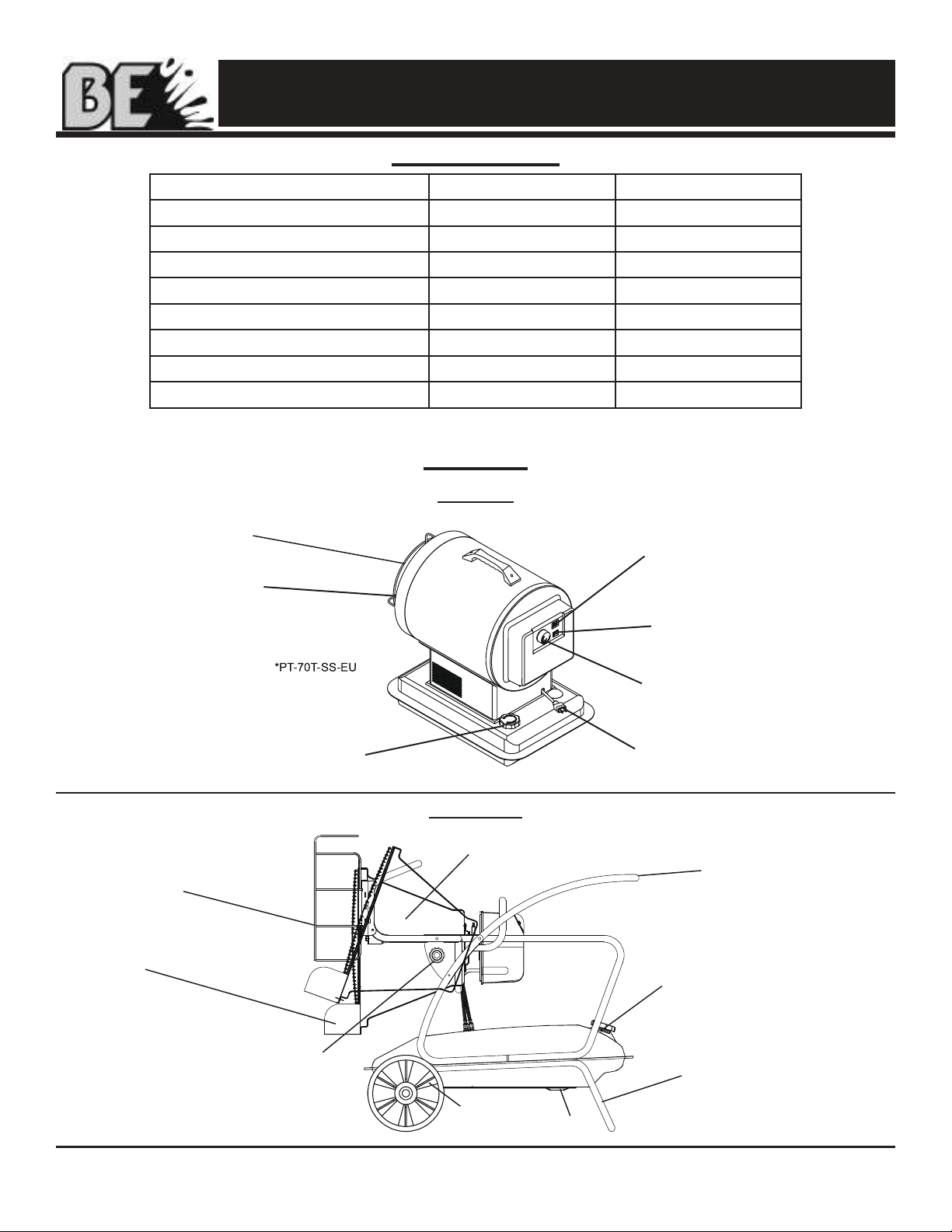
Minimum Clearance From Combustibles
HK070-R HK125-RW
Top 1.2 m 1.2 m
Sides 1.2 m 1.2 m
Front 2.4 m 2.4 m
ALWAYS locate heater on a stable and level surface.
If your heater is equipped with a thermostat,
once it is plugged in, it can start at anytime in
accordance with the thermostat setting.
RISK OF INDOOR AIR
POLLUTION!
WARNING
CARBON MONOXIDE POISONING
MAY LEAD TO DEATH!
WARNING
RISK OF BURNS, FIRE AND
EXPLOSION!
WARNING
RISK OF ELECTRIC SHOCK!
WARNING
CAUTION! HOT WHILE IN
OPERATION. DO NOT TOUCH.
KEEP CHILDREN, ANIMALS, CLOTHING AND
COMBUSTIBLES AWAY FROM HEATER.
WARNING

NEVER LEAVE HEATER UNATTENDED WHILE BURNING OR WHILE
CONNECTED TO A POWER SOURCE
Oil Fired Radiant Heater User’s Manual
© 2019, BE Pressure Australia 3
Features
HK070-R
HK125-RW
Figure 1
Figure 2
Radiant Cone
Front Safety
Guard
Radiant
Visor
Adjustment Knob
Can Tilt Up To 15°
Wheel Drain Bolt
Wheel Frame
Fuel Cap
Handle
Specications
Model # HK070-R HK125-RW
Rating: kW/Hr 20.5 37
Fuel Consumption: L/Hr 1.9 3.4
Fuel Tank Capacity: L 15.1 53
Max Operating Hours 7.2 20
Volts: AC/Hz 240VAC / 50Hz 240VAC / 50Hz
Heating Area m2186 290
Weight (kg) 14.5 39
Noise (dBA) 71 75
Specications subject to change without notice.
Heat Plate
Safety Guard
Lamp
Operating Switch
Thermostat Knob
Power Cord
Fuel Cap

NEVER LEAVE HEATER UNATTENDED WHILE BURNING OR WHILE
CONNECTED TO A POWER SOURCE
Oil Fired Radiant Heater User’s Manual
© 2019, BE Pressure Australia 4
Assembly Instructions
HK070-R
What’s In The Box
Carry Handle (1) Black Screws (2)
Carry Handle Assembly
1. Align holes in the upper housing with the 2
holes in the handle as shown in Figure 3.
2. Insert screws and tighten firmly.
Tools Needed:
- Phillips Head Screw Driver
Figure 3
- Remove the heater and all packaging materials
from the shipping carton. Note: Save the box and packaging materials
for future storage.
Figure 4
Attach the handle while still in the box
for easier unpacking. (See Figure 4)

NEVER LEAVE HEATER UNATTENDED WHILE BURNING OR WHILE
CONNECTED TO A POWER SOURCE
Oil Fired Radiant Heater User’s Manual
© 2019, BE Pressure Australia 5
- Remove the heater and all packaging
materials from the shipping carton. Tools Needed:
- Phillips Head Screw Driver
- 8 mm open end wrench
Assembly Instructions
Tip: Be sure to remove the axle from the
side of the Styrofoam packaging. Tip: Use a power screwdriver and
locking wrench for easier assembly.
What’s In The Box
Long Screws (6) Short Screws (4) 8 mm Nuts (6) Wheels (2)
Visors 19 mm Axle Nuts (2)
Spacers (2)
Axle (1)
Safety Guards (Top, Front) Wheel Frame

NEVER LEAVE HEATER UNATTENDED WHILE BURNING OR WHILE
CONNECTED TO A POWER SOURCE
Oil Fired Radiant Heater User’s Manual
© 2019, BE Pressure Australia
Assembly Instructions
HK125-RW
6
Assembly
1. Slide axle through Wheel Frame and attach
wheels, washers and nuts.
2. Place main structure on wheel frame and
fasten with long screws provided.
3. Attach safety guard to front of heater with
screws provided.
4. Attach Radiant Visors to the top and bottom
rear of the Radiant Cone Assembly using extra
screws included.
5. Attach top safety guard using the two
outer-most extra screws on the top of the
radiant cone (See photo).
Note: Save the box and packaging materials for
future storage.
Screws
Radiant
Cone
Assembly
Safety
Guard
Radiant Visor

NEVER LEAVE HEATER UNATTENDED WHILE BURNING OR WHILE
CONNECTED TO A POWER SOURCE
Oil Fired Radiant Heater User’s Manual
© 2019, BE Pressure Australia
Operation
Fueling The Heater:
Parafn
For optimal performance of this heater, it is
strongly suggested that Parafn be used.
Parafn has been rened to virtually eliminate
contaminants, such as sulfur, which can cause
a rotten egg odor during the operation of the
heater. Using diesel fuel can cause excess soot
production. Do not use Bio-Diesel as this fuel will
damage your heater’s seals and lter.
- NEVER use fuel such as, benzene, alcohol, white
glass, camp stove fuel, paint thinners, or other oil
compounds in this heater. THESE ARE VOLATILE
FUELS THAT CAN CAUSE A FIRE OR
EXPLOSION.
- NEVER store Paraffin in the living space. Paraffin
should be stored in a well ventilated area outside
the living area.
- NEVER store Paraffin in direct sunlight or near a
source of heat.
- NEVER use Paraffin that has been stored from one
season to the next. Paraffin deteriorates over time.
OLD PARAFFIN WILL NOT BURN PROPERLY IN
THIS HEATER.
NOTE: Parafn should only be stored in
a blue container that is clearly marked
“Parafn.” Never store Parafn in a red
container. Red is associated with gasoline.
Ventilation:
- Risk of indoor air pollution and Carbon
Monoxide Poisoning. Use heater only in well
ventilated areas.
- Refer to Safety Information on pages 1-2 for
information about Carbon Monoxide Poisoning.
- ALWAYS provide a fresh air opening in the heated
space of at least 2,800 cm
2
(3 sq. ft) for each 29 kW / Hr. of heater output.
Provide a larger opening if more heaters are being
used.
As an example, a HK125-RW will require:
- Atwo car garage door open 16 cm or
- A single car garage open 22 cm or
- Two (2) 82 cm windows open 38.5 cm
Minimum Ventilation Opening Needed
HK070-R HK125-RW
1950 cm23484 cm2
NEVER FILL THE FUEL TANK
INDOORS. ALWAYS FILL
THE TANK OUTDOORS. BE SURE THAT
THE HEATER IS ON LEVEL GROUND WHEN
FUELING, AND NEVER OVERFILL THE TANK.
CAUTION
NEVER REFUEL THIS HEATER
WHILE IT IS HOT OR
OPERATING. FIRE OR EXPLOSION COULD
RESULT.
DANGER
CARBON MONOXIDE POISONING
MAY LEAD TO DEATH!
DANGER
7
DO NOT USE GASOLINE OR
CRANKCASE DRAININGS.
WARNING
This appliance is designed to
operate safely at a minimum
ambient temperature of -20° C.
WARNING
Use caution when servicing in
wet areas. Disconnect power
from the power mains and keep all electrical
components from becoming wet. Only a
qualified technician should service the
heater
WARNING
A qualified technician is
required to install, adjust and
where necessary; convert this heater for use
with other fuel types.
WARNING

NEVER LEAVE HEATER UNATTENDED WHILE BURNING OR WHILE
CONNECTED TO A POWER SOURCE
Oil Fired Radiant Heater User’s Manual
© 2019, BE Pressure Australia 8
Operation: HK070-R / HK125-RW
Starting the Heater: (Ignition)
1. Fill the tank with Kerosene or other approved
fuel.
2. Replace fuel cap and tighten firmly.
3. Connect the heater to a three prong
(grounded) power source. You must use a
three prong (grounded) extension cord that is
at least 1.8 meters long and is a minimum of
14 AWG rating.
NOTE: On first ignition or after refueling,
you may hear a grinding sound just before
ignition. This is the fuel pump removing the
air from the fuel line. Your heater will start up
within seconds. If it does not start repeat
start-up procedures with fuel gauge reading at
least 1/2 tank.
NOTE: The electrical components of these
heaters are protected by a fuse mounted
in the PC board. If the heater fails to ignite,
check this fuse first and replace if necessary.
Also check the power source to be sure the
proper voltage is being provided to the heater.
1. Complete steps 1-3 above.
2. Push the power switch to the “ON” position.
The power indicator lamp will light and heater
will ignite. (See Figure 5)
Stopping the Heater: (Cool Down)
1. Turn the power switch to the “OFF” position.
Combustion will stop and the Cooling Cycle
will begin.
- HK070-R: approx. 7 mins
- HK125-RW: approx 3 mins
When the Cooling Cycle is complete the fan
will stop running and it will be safe to unplug
the heater.
NOTE: Unplugging the heater before the
Cooling Cycle has been completed may cause
overheating, possible damage to the heater and
heat plate.
Restarting the Heater:
1. Wait ten seconds after Cooling Cycle has
been completed.
2. Follow all start-up procedures above.
DO NOT disconnect heater
from power source before
cooling cycle has been completed.
WARNING
Thermostat Knob
Digital Display
(2% Tolerance with
actual temperature)
Power Switch

NEVER LEAVE HEATER UNATTENDED WHILE BURNING OR WHILE
CONNECTED TO A POWER SOURCE
Oil Fired Radiant Heater User’s Manual
© 2019, BE Pressure Australia
Maintenance - HK070-R
Long Term Storage:
1. Unscrew the fuel cap.
2. Using an approved siphon (Figure 11.1),
remove the Parafn or diesel.
3. Using a small amount of Parafn or diesel,
rinse and swirl the fuel inside the fuel tank
NOTE: NEVER MIX WATER WITH FUEL. It will
cause rust inside the tank.
4. Empty the tank completely.
IMPORTANT: Never store leftover Parafn
between seasons, using old fuel can
damage heater.
Store Heater in a dry, well ventilated area.
- Be sure that the storage area is free of dust
and corrosive vapors. Repack the heater
in the original packaging and keep user’s
manual in an easily accessible place.
Service:
DO NOT TAMPER WITH THE UNIT. HAVE AN
EXPERIENCED SERVICEMAN MAKEANY
NECESSARYADJUSTMENT OR REPAIRS.
We suggest following a maintenance schedule as
follows:
FUEL / FUEL TANK:
Flush tank every 200 hours of operation or as
needed. DO NOT ush with water, use fresh
Parafn only.
SPARK PLUG:
Clean and re-gap every 600 hours of operation
or replace as needed. After removing the Spark
Plug, clean the terminals with a wire brush.
Re-gap the terminals to 0.140” (3.5mm).
(See Figure 11.2)
FAN BLADES:
The fan blades should be cleaned at least once
per heating season, depending on conditions.
Remove all accumulated dust and dirt with a
burst of condensed air. (See Figure 12)
9
TIP: Follow the long term storage
instructions to ush the tank.
Never service heater while it is
plugged in or hot!
WARNING
Figure 12
Figure 11.2
Figure 11.1
Suction Type:
Manual squeezing pump

NEVER LEAVE HEATER UNATTENDED WHILE BURNING OR WHILE
CONNECTED TO A POWER SOURCE
Oil Fired Radiant Heater User’s Manual
© 2019, BE Pressure Australia
Maintenance - HK070-R
Service (Continued):
NOZZLES:
Nozzles should be cleaned or replaced at least
once per heating season. Contaminated fuel
could make this necessary immediately. To clean
dirt from nozzle, blow compressed air through
nozzle front. It may be necessary to soak nozzle
in clean parafn or diesel to help loosen any
particles. (See Figure 13)
PHOTOCELL:
The photocell should be cleaned at least once
per heating season or more depending on
conditions. Use a cotton swab and water or
alcohol to clean the lens of the photocell.
Be certain to reinstall the photocell in proper
position as shown below. (See Figure 14)
FILTERS:
The fuel filter and oil filter should be cleaned at
least twice per heating season by rinsing it in
clean paraffin or diesel. Contaminated or old fuel
could make cleaning necessary immediately.
(See Figure 15)
10
Figure 13
Figure 15
Figure 14

NEVER LEAVE HEATER UNATTENDED WHILE BURNING OR WHILE
CONNECTED TO A POWER SOURCE
Oil Fired Radiant Heater User’s Manual
© 2019, BE Pressure Australia
Maintenance - HK125-RW
Long Term Storage:
1. Unscrew the drain bolt and drain all fuel.
(See Figure 17)
2. Using a small amount of Parafn or diesel,
rinse and swirl the fuel inside the fuel tank.
NOTE: NEVER MIX WATER WITH FUEL. It will
cause rust inside the tank.
3. Empty the tank completely.
IMPORTANT: Never store leftover Parafn
between seasons, using old fuel can
damage heater.
Store Heater in a dry, well ventilated area.
- Be sure that the storage area is free of dust
and corrosive vapors. Repack the heater
in the original packaging and keep user’s
manual in an easily accessible place.
Service:
DO NOT TAMPER WITH THE UNIT. HAVE AN
EXPERIENCED SERVICEMAN MAKEANY
NECESSARYADJUSTMENT OR REPAIRS.
We suggest following a maintenance schedule as
follows:
FUEL / FUEL TANK:
Flush tank every 200 hours of operation or as
needed. DO NOT ush with water, use fresh
Parafn only.
SPARK PLUG:
Clean and re-gap every 600 hours of operation,
or replace as needed After removing the Spark
Plug, clean the terminals with a wire brush.
(See Figure 18)
NOZZLES:
Nozzles should be cleaned or replaced at least
once per heating season. Contaminated fuel
could make this necessary immediately.
To clean dirt from nozzle, blow compressed air
through nozzle front. It may be necessary to
soak nozzle in clean diesel to help loosen any
particles (Figure 19).
11
Never service heater while it is
plugged in or hot!
WARNING
TIP: Follow the long term storage
instructions to ush the tank.
SPARK PLUG
Figure 19
Figure 17
Figure 18

NEVER LEAVE HEATER UNATTENDED WHILE BURNING OR WHILE
CONNECTED TO A POWER SOURCE
Oil Fired Radiant Heater User’s Manual
© 2019, BE Pressure Australia 12
Maintenance - HK125-RW
Service (Continued):
PHOTOCELL:
The photocell should be cleaned at least once
per heating season or more depending on
conditions. Use a cotton swab and water or
alcohol to clean the lens of the photocell.
(See Figure 21)
Be certain to reinstall the photocell in proper
position as shown below. (See Figure 20)
FILTERS:
The fuel filter and oil filter should be cleaned at
least twice per heating season by rinsing it in
clean paraffin or diesel. Contaminated or old fuel
could make cleaning necessary immediately.
(See Figure 22)
Figure 20
Figure 21
Figure 22

NEVER LEAVE HEATER UNATTENDED WHILE BURNING OR WHILE
CONNECTED TO A POWER SOURCE
Oil Fired Radiant Heater User’s Manual
© 2019, BE Pressure Australia 13
Troubleshooting Guide
Problem Possible Cause Solution
Heater fires, but shuts down after a
short period of time.
1. Dirty Fuel Filter.
2. Nozzle Dirty.
3. Photocell Dirty.
4. Photocell not installed properly.
5. Photocell Defective .
6. Improper electrical connec-
tion between Circuit Board and
Photocell.
7. Cooling Fan is obstructed
1. Clean/replace Fuel Filter.
2. Clean/replace Nozzle
3. Clean/replace Photocell .
4. Adjust Photocell position.
5. Replace Photocell.
6. Check wiring connections (See
Wiring Diagrams, Page 14).
7. Check to be sure cooling fan is not
obstructed.
Heater will not operate, or motor
runs for short time.
1. No paraffin/ diesel in fuel tank.
2. Corroded Spark Plug or incorrect
plug gap.
3. Dirty Fuel Filter.
4. Dirty Nozzle.
5. Moisture in Fuel/Fuel Tank.
6. Improper electrical connection
between Transformer and Circuit
Board.
7. Transformer Wires not connected to
Spark Plug.
8. Defective Transformer.
1. Fill tank with fresh paraffin/ diesel.
2. Clean/replace Spark Plug.
3. Clean/replace Fuel Filter.
4. Clean/replace Nozzle.
5. Rinse out fuel tank with clean fresh
paraffin/ diesel.
6. Inspect all electrical connections.
(See Wiring Diagrams, Page 14).
7. Re-attach Transformer wires to
Spark Plug.
8. Replace Transformer.
Fan does not operate when heater
is plugged in and Operating Switch
is in the “ON” position.
1. Broken electrical connection
between Circuit Board and motor.
2. Not enough amps available to power
heater.
1. Inspect all electrical connections on
Wiring Diagrams (Page 14).
2. Use a new extension cord or try
another electrical socket.
Heater makes grinding noise. 1. Air in fuel pump. 1. Sound will stop after 3 seconds. If
grinding sound continues, add fuel to
tank.
Heater does not turn on and the
lamp is not lit.
1. Temperature limit sensor has over-
heated.
2. No electrical power.
3. Fuse break down.
4. Improper electrical connection
between Temperature Limit Sensor
and Circuit Board.
1. Push Operating Switch to “OFF” and
allow heater to cool for 5 minutes.
Push Operating Switch back to “ON”.
2. Check power cord and extension
cord to insure of proper connection.
Test power supply.
3. Check/replace Fuse.
4. Inspect all electrical connections.
(See Wiring Diagrams, Page 14).
Poor combustion and / or soot
production.
1. Pump Pressure.
2. Poor fuel quality.
1. Be sure pump pressure is adjusted
correctly.
2. Be sure paraffin/ diesel is not old or
contaminated.

NEVER LEAVE HEATER UNATTENDED WHILE BURNING OR WHILE
CONNECTED TO A POWER SOURCE
Oil Fired Radiant Heater User’s Manual
© 2019, BE Pressure Australia 14
Wiring Diagrams
AC230V/50Hz
250V/3.15A
HK070-R
HK125-RW
Figure 23
Figure 24
AC240V/50Hz

NEVER LEAVE HEATER UNATTENDED WHILE BURNING OR WHILE
CONNECTED TO A POWER SOURCE
Oil Fired Radiant Heater User’s Manual
© 2019, BE Pressure Australia 15
Exploded View
HK070-R
1
2
3
4
5
6
7
8
10
11
12
13
14
15
16
18
18
19
20
21
22 23 24 25
26 27
28
29
30
31
32
33
34
35
36
37
40
42
41
38
39
9
43
# Part Previous Current
1Fuel Tank Assembly 75-011-0350 01.01.75.007010691
2Fuel Filter 75-023-0285 75-023-0285
3Fuel Pipe 75-023-0345 01.03.71.015010074
4Fuel Packing 75-023-0355 01.03.75.007010042
5Fuel Hose 75-024-0700 75-024-0740
6Fuel Gauge 75-022-0210 01.04.75.007010071
7Fuel cap 70-006-0135 70-006-0140
8Cooling Fan Housing N/A 75-011-0685
9Control Knob 75-012-0110 01.02.75.107020060
10 Power Switch wire Assembly 75-012-0220 01.04.75.007010087
11 Electronic Pump 75-027-0261 01.01.75.207020001
12 Igniter 75-075-0200 01.04.70.104520033
13 Main PCB with Thermostat 75-025-0455 01.04.75.207020002
14 Tip Over Sensor 75-051-0200 01.04.75.007010149
15 Tip over Sensor Wire Assembly 75-051-0260 01.04.75.007010086
PARTS LIST

NEVER LEAVE HEATER UNATTENDED WHILE BURNING OR WHILE
CONNECTED TO A POWER SOURCE
Oil Fired Radiant Heater User’s Manual
© 2019, BE Pressure Australia
PARTS LIST
16
# Part Previous Current
16 Motor 75-045-0270 01.04.75.607020260
17 Plastic Fan Blade 75-047-0200 01.02.75.007010054
18 Outer Shell 75-011-1110 01.01.75.007020694
19 Handle 75-001-0060 01.02.75.007010055
20 Burner Body Supporter 75-011-1100 01.01.75.007010346
21 Temperature Limit Control 75-040-0110 01.04.75.007020685
22 Chamber Insulator 75-035-0800 01.01.75.007010222
23 Shell Insulator 75-035-0820 01.01.75.007010220
24 Ceramic Fiber 75-035-0830 01.03.75.007010038
25 Heat Plate 75-012-0600 01.01.75.007010690
26 Shell Ring 75-011-0650 01.01.75.007010206
27 Safety Guard 75-012-0310 01.01.75.007010205
28 Burner Body 75-036-0185 01.01.75.007020686
29 Spark Plug 75-075-0200 01.04.75.007010078
30 Burner Blade 75-036-0120 01.01.75.007010700
31 Nozzle 75-036-0435 01.01.75.007020215
32 Nipple 75-040-0610 01.01.75.007010203
33 Diffusion cap 75-036-0500 01.01.75.007010209
34 Blower Motor 75-045-0205 01.04.75.607020261
35 Photocell 75-038-0200 01.04.75.007010083
36 Back Cover 75-013-0106 01.02.75.207020001
37 Power Cord 75-032-0185 01.04.75.507020153
38 Return Pipe 75-055-0100 01.01.75.007010204
39 Return Hose 75-055-0100 01.01.75.007010204
40 Pump Bracket 75-027-0255 01.01.75.007010195
41 Display PCB 75-013-0150 01.04.75.107020155
42 Thermistor 75-026-0100 01.04.70.007010019
43 Power Switch 75-012-0100 01.04.75.007010088
44 PCB cable Connected to Display Board 01.04.75.107020156
45 Sub PCB N/A N/A
-Back Panel (not shown) New in 2017 75-011-0690
-Pump Connector (not shown) New in 2017 75-027-0630
-Inlet Tube Assembly (not shown) New in 2017 75-024-0725
-Hose Clamp (not shown) New in 2017 75-001-0505

NEVER LEAVE HEATER UNATTENDED WHILE BURNING OR WHILE
CONNECTED TO A POWER SOURCE
Oil Fired Radiant Heater User’s Manual
© 2019, BE Pressure Australia
Exploded View - HK125-RW
17
ALWAYS contact the manufacturer of this heater before replacing any parts
other than those specified or recommended in the servicing instructions.
WARNING
/

NEVER LEAVE HEATER UNATTENDED WHILE BURNING OR WHILE
CONNECTED TO A POWER SOURCE
Oil Fired Radiant Heater User’s Manual
© 2019, BE Pressure Australia 18
Parts List: HK125-RW
# Part Previous Current
1Fuel Tank Assembly 72-001-0200 01.01.72.012510632
2Fuel Gauge Assembly 72-022-0130 01.04.72.012510105
3Fuel Tank Cap Assembly 72-035-0615 70-006-0140
4 Wheel 72-041-1400 01.03.90.003610031
5 Axle 72-041-0200 01.01.72.012510253
6Wheel Frame 72-042-0120 01.01.72.012510240
7Drain Bolt 72-002-0220 01.01.72.012510245
8Transport Handle 72-042-0220 01.01.72.012510238
9Rear Frame 72-042-0320 01.01.72.012510239
10 Pump Support Plate 72-025-0510 01.01.72.012510232
11 Frame Support N/A N/A
12 Height Adjustment Knob 72-042-0500 01.02.72.012510064
13 Return Fuel Line 72-023-0260 01.03.71.015010074
14 Intake Fuel Line 72-023-0260 01.03.72.012510049
15 Fuel Filter Assembly 72-020-0100 01.02.72.012510062
16 Fuel Pump Assembly 72-027-0100 01.01.72.312520263
17 Main PCB and Fuse 72-025-0450 01.04.72.012520685
18 Intake Fuel Hose 72-023-0310 01.03.72.012510050
19 Tip Over Sensor 75-051-0200 01.04.75.007010149
20 Power Cord 72-032-0200 01.04.72.412520247
21 Power Switch 72-012-0100 01.04.72.312520120
22 Back Cover 72-013-0110 01.02.72.012510061
23 Panel sub-PCB 72-014-0105 01.04.72.012510107
24 Blower Motor Assembly 72-045-0100 01.04.72.312520116
25 Photocell Assembly 72-038-0200 01.04.75.007010083
26 Spark Plug 75-075-0200 01.04.75.007010078
27 Burner Body 72-035-0210 01.01.72.012510250
28 Nozzle 72-036-0100 01.01.72.312520264
29 Burner Blade 72-035-0500 01.01.72.012510635
30 Diffusion Cap 72-036-0200 01.01.72.012510248
31 Ignitor 72-025-0120 01.04.70.104520033
32 Burner Support Plate 72-035-0110 01.01.72.012510331
33 Temperature Overheat Sensor (not shown) 72-040-0120 01.04.72.012510104
34 Radiant Cone Support Assembly 72-035-0680 01.01.72.012510237
35 Radiant Cone Assembly 72-035-0610 01.01.72.012510246
36 Ceramic Fiber 72-035-0610 01.03.72.012510043
37 Heat Plate 72-012-0200 01.09.75.007010002
38 Safety Guard 72-012-0200 01.01.72.012510242
39 Front Frame 72-042-0220 01.01.72.012510238
40 Burner Bracket 72-035-0700 01.01.72.012510234
41 Radiant Visor 72-012-0220 01.01.72.012510225
42 Burner Housing Gasket 72-035-0630 01.03.72.012510046
43 Burner Bracket Gasket 72-035-0630 01.03.72.012510045
44 Burner Head Gasket 72-035-0215 01.03.72.012510047

NEVER LEAVE HEATER UNATTENDED WHILE BURNING OR WHILE
CONNECTED TO A POWER SOURCE
Oil Fired Radiant Heater User’s Manual
© 2019, BE Pressure Australia 19
Model #:________________________________
Serial #:________________________________
Date of Purchase: ________________________
Locating Your Serial Number:
Your serial number can be found on a blue label on the left side cover. For Example: S150100001, where the
year of manufacture is represented by the 2 digits immediately following the rst letter.
XXXXXXXXXX
Serial Number Label
This manual suits for next models
1
Table of contents
Other BE Heater manuals