SpaNet Power Smart SHP-60 Instruction Manual

Innovative Spa & Pool Solutions
INSTALLATION &
MAINTENANCE
MANUAL
SHP-60 SHP-80
SHP-100 SHP-140
SHP-170 SHP-190

2
Table of Contents
1. Safety precautions
2. Technical description
2.1 Specications
3. Touch pad operation
3.1 LCD display and touch pad control
3.2 Set the operation parameter
3.3 Powering the unit
3.4 Selecting the operation mode
3.5 Setting the temperature
3.6 Check the current temperature
3.7 Setting the time
3.8 Timer ON/OFF
3.9 Coercive defrosting
3.10 Key lock
4. Safety and control systems
4.1 Water ow switch
4.2 Refrigerant gas high-and-low pressure protection
4.3 Overheating protection on the compressor
4.4 Automatic defrost control
4.5 Anti-frost protection during winter
4.5.1 First anti-frost protection
4.5.2 Second anti-frost protection
4.6 Three phase protection
5. Installation
5.1 Recommended air ow requirements
5.2 Location of the unit
5.3 Installation of water
5.4 Heat pump plumbing diagram
5.5 Electric connection
6. Water ow and refrigerating circuit pressure
7. Problematic environmental conditions
8. Maintenance and inspection
8.1 Maintenance
8.2 Troubleshooting guide
8.3 Overview of possible error codes displayed on the screen
3
5
5
5
5
7
9
10
10
11
12
12
12
12
13
13
13
13
13
13
13
13
14
14
14
15
16
17
18
18
19
21
21
19
19
3
1. Safety Precautions
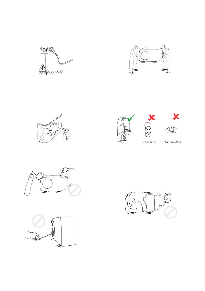
VITAL: Electrical power must be switched off before starting any work on heat pump.
DO NOT attempt to modify the internal conguration of the heat pump. Read the entire
installation manual before use or service.
The unit must be earthed to avoid any risks
caused by insulation defects. The heat
pump will be earthed via the pre-installed
power cable which connects to the spa
control. If a different power source is used,
ensure heat pump is connected to earth.
You can clean the evaporator by washing
with detergent and water at low pressure,
and then rinsing with clean water.
Do not spray or paint insecticidal material
on the surface of the unit.
Do not touch the air outlet grill when fan
motor is running.
Children should be supervised to ensure
that they do not play with the appliance.
The installation, commissioning and
maintenance of these machines should be
performed by qualied personnel having
a good knowledge of standards and local
regulations, as well as experience with this
type of equipment.
It is the responsibility of the installer
to ensure circuit breaker protection,
considering the heat pump capacity. The
heat pump should also be supplied through
a residual current device (RCD) having
a rated residual operating current not
exceeding 30mA.
Do not block the evaporator by paper or
any other foreign bodies, to keep the unit
well ventilated.
This appliance is not intended for use by
persons (including children) with reduced
physical, sensory or mental capabilities,
or lack of experience and knowledge,
unless they have been given supervision or
instruction concerning use of the appliance
by a person responsible for their safety.

4
VITAL: Unless you are certain the heat pump has always remained in its upright
installation orientation during transit and throughout the installation process, and has
not been laid on its side or end at any time, the heat pump should NOT be used for 24
hours after its installation to prevent damage to the compressor.
• The heat pump is pre-installed with a power cable for direct power connection
to a suitable power point. If the installer decides to connect power to the heat pump from
a source, all electrical connections must be performed by a licensed electrician and must
conrm to all national, state and local electrical codes in effect at the time of installation.
• The heat pump must be connected to a suitable rated and weather protected power
supply. The supply line should be a dedicated power circuit and means for disconnection
must be incorporated in the xed wiring in accordance with your local wiring regulations.
Means for disconnection from the supply mains should have a contact separation in all
poles that provide full disconnection under over voltage Category III conditions.
• The appliance contains no serviceable parts. Do not attempt service of this appliance.
Contact your dealer or authorized service agent for assistance.
• Turn the mains power OFF before touching or modifying any cable connection.
• Low voltage or improper wiring may cause damage to this appliance. Read and follow
all wiring instructions when connecting to power supply.
• If the supply cord is damaged, it must be replaced by the manufacturer, its service
agent or similarly qualied persons in order to avoid a hazard.
• This appliance must not be installed in proximity to highly ammable materials.
• Water temperature in excess of 38oC may cause hyperthermia (heat stress).
• It is the installer’s responsibility to ensure the oor or mounting base is capable of
supporting the expected load of the heat pump and an adequate drainage system has to
be provided in case of overowing or leaking water.
• The heat pump should be plumbed after the spa lters and NOT before, to prevent
foreign objects or debris from entering heat pump.
WARNING: When ambient temperatures are close to or under freezing point, water
circulation to the heat pump should never be stopped for more than 4 hours without
completely draining the heat exchange. In areas where freezing conditions are
prevalent and sustained, in advance of any freeze event, all water MUST be removed
from the entire heat pump water circuit. Please refer to the “Winterising” section of
this manual. FREEZE DAMAGE NOT COVERED UNDER PRODUCT WARRANTY

5
2. Technical Description
2.1 Specications
Model SHP-60P SHP-80P SHP-140 SHP-170 SHP-190
Power supply 230V~,
50Hz
230V~,
50Hz
230V~,
50Hz
230V~,
50Hz
230V~,
50Hz
Heating consumption
power* (kW)
1.1 1.5 2.6 3.1 3.4
Heating restored power*
(kW)
6 8.3 14 17 19.5
Heating nominal
intensity* (A)
5.3 7.2 12.8 15 19
Cooling absorptive
power* (kW)
1.2 1.6 2.7 3.2 3.5
Cooling restored power*
(kW)
4.3 5.8 9.7 11.5 14.5
Cooling nominal
intensity* (A)
5.8 7.8 13.6 16 20.3
Air ow (m3/h) 1700 1700 3200 4000 4000
Noise level
(d(B)A)
<48 <49 <52 <53 <54
Refrigerant gas R410a R410a R410a R410a R410a
Rate of average lling of
gas (g)
620 850 1450 1650 2100
Net weight of the unit
(kg)
51 55 77 97 100
Overall sizes L x W x H
(cm)
99x36
x62
99x36
x62
112x48
x84
112x48
x84
112x48
x84
* Possible variations of value according to climatic conditions
** Heating by max ambient temperature: 27°C
*** Cooling by max ambient temperature: 43°C
3. Touch Pad Operation
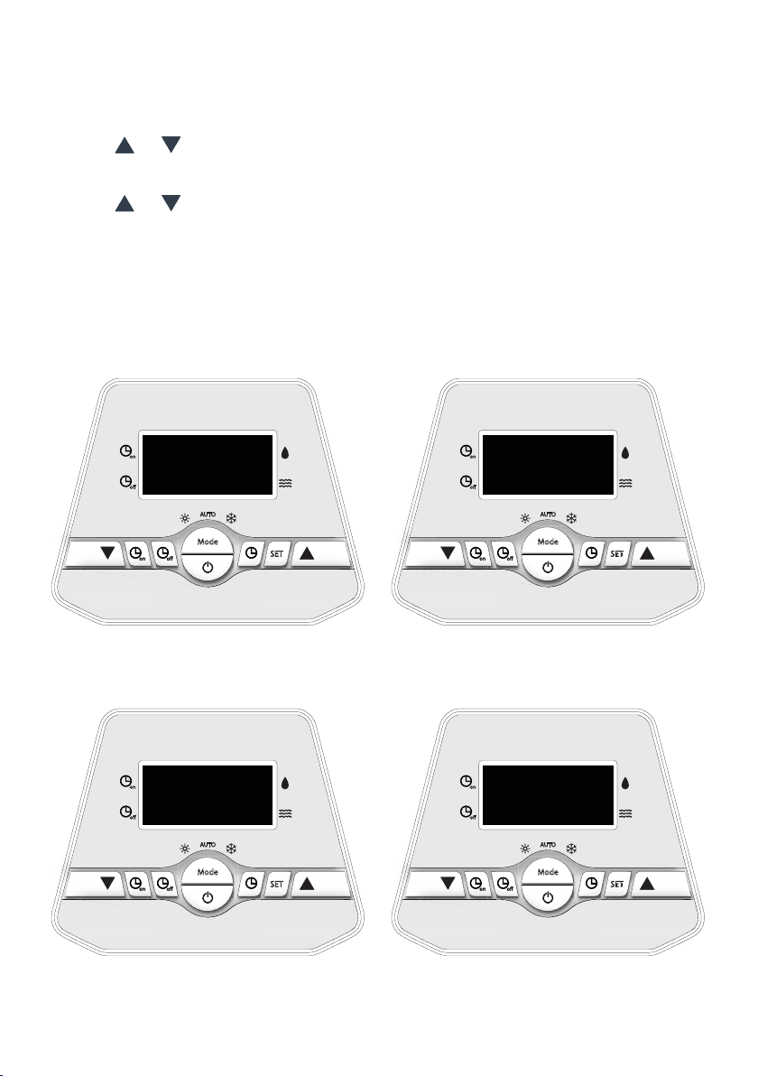
3.1 LCD Display and Touch Pad Control

6
No Meaning Range Change Factory Setting
0Cooling setting water temperature 10 - 27°C YES 27
1Heating setting water temperature 10 - 27°C YES 27
2Turnround of defrosting under heat mode 30 - 90 min YES 45 min
3Defrosting start temperature -30 - 0°C YES -7°C
4Defrosting exit temperature 2 - 30°C YES 13°C
5Time of exit defrost under heat mode 1 - 12min YES 5 min
6Mode (cool/cool&heat/electric heat/heat) 0/1/2/3 YES 1
7Mode of electronic expansion valve (0 for
‘MAN’ and 1 for ‘AUTO’)
0/1 NO 1
8Heating Target Superheat -15 - 15°C NO 3°C
9Cooling Target Superheat -15 - 15°C NO 3°C
AAuto mode setting water temperature 10 -27°C YES 27
bCompressor protection exhaust temperature 85 - 110°C NO 95°C
cLow ambient temperature protection -20 - 10°C YES -7°C
dManual control for EE valve 18 - 94 NO 70
EWater temperature -9 - 99°C Measured value
FCompressor exhaust temperature -9 - 125°C Measured value
GHeating coil temperature -9 - 99°C Measured value
HReturn gas temperature -9 - 99°C Measured value
LAmbient temperature -9 - 99°C Measured value
NCooling temperature -9 - 99°C Measured value
PActual open steps of EE valve N*5 Measured value
on
off
Mode
SET
offon
AUTO
12.00
MODE button
LED display
DOWN button
CLOCK button
ON/OFF button
UP button
SET button
TIMER button
7
on
off
Mode
SET
offon
AUTO
on
off
Mode
SET
offon
AUTO
on
off
Mode
SET
offon
AUTO
on
off
Mode
SET
offon
AUTO
Parameter 0: Cooling setting water
temperature (10-45°C).
Factory setting: 27°C
Parameter 2: Turnround if defrosting
under heat mode (30-90 min).
Factory setting: 45 minutes
Parameter 1: Heating setting water
temperature (10-45°C).
Factory setting: 27°C
Parameter 3: Defrosting start temperature
(-30-0°C). Factory setting: -7°C
0 27
2 45
1 27
3 -7
3.2 Set the Operation Parameter
1. Press & hold the “SET” button for 5 seconds to enter the operation parameter setting
interface.
2. Press or to check parameter.
(parameter from 0-P, see Operation Parameter Table).
3. Under parameter, press “ SET “ to start setting (the parameter displayed blinks).
Press or to set data for parameter from 0-d. Press “ SET “ again to exit the
current parameter settings.
4. Wait for 5 seconds. The LCD screen will display the water temperature (If heat pump is
running) or the current time (if the heat pump is OFF).
5. Whilst the unit is running, you can press & hold the “SET” button for 5 seconds to check
the current parameter, but you cannot change the value.

8
on
off
Mode
SET
offon
AUTO
on
off
Mode
SET
offon
AUTO
Parameter 4: Defrost exit temperature.
(2-30°C)
Factory setting: 13°C
Parameter 5: Time of exit defrost under
heat mode (1-12 min)
Factory setting: 5 minutes
4 13 5 5
on
off
Mode
SET
offon
AUTO
on
off
Mode
SET
offon
AUTO
on
off
Mode
SET
offon
AUTO
on
off
Mode
SET
offon
AUTO
Parameter 6: Mode (0/1/2/3)
Factory setting: 1
Parameter 8: Heating target superheat
(-15-15°C). Factory setting: 3°C
Parameter 7: Mode of electronic
expansion valve (0 for ‘MANUAL’ and 1 for
‘AUTO’). Factory setting: 1
Parameter 9: Cooling target superheat
(-15-15°C). Factory setting: 3°C
6 1
8 3
7 1
9 3

9
3.3 Powering the Unit
Press to power on the unit. Whilst ON, the LED displays the water temperature.
on
off
Mode
SET
offon
AUTO
on
off
Mode
SET
offon
AUTO
C -7 d 70
Parameter C: Low ambient temperature
protection (-20-10°C).
Factory setting: -7°C
Parameter d: Manual control for EE valve
(18-94). Factory setting: 70
on
off
Mode
SET
offon
AUTO
ON/OFF button
27
on
off
Mode
SET
offon
AUTO
on
off
Mode
SET
offon
AUTO
Parameter A: Auto mode setting water
temperature (10-45°C).
Factory setting: 27°C
Parameter b: Compressor protection
exhaust temperature for heating (85-110°C).
Factory setting: 95°C
A 27 b 95
10
on
off
Mode
SET
offon
AUTO
on
off
Mode
SET
offon
AUTO
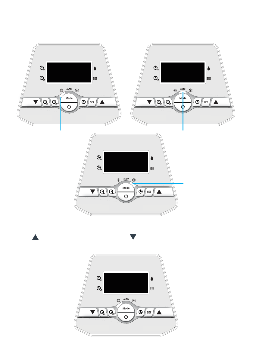
27
Auto mode
Cooling mode
on
off
Mode
SET
offon
AUTO
Heating mode
27 27
3.5 Setting Temperature
Press to set temperature 1°C higher, press to set temperature 1°C lower.
3.4 Selecting the Operation Mode
Press “MODE” to choose mode. The mode can only be changed while ON.
on
off
Mode
SET
offon
AUTO
27

11
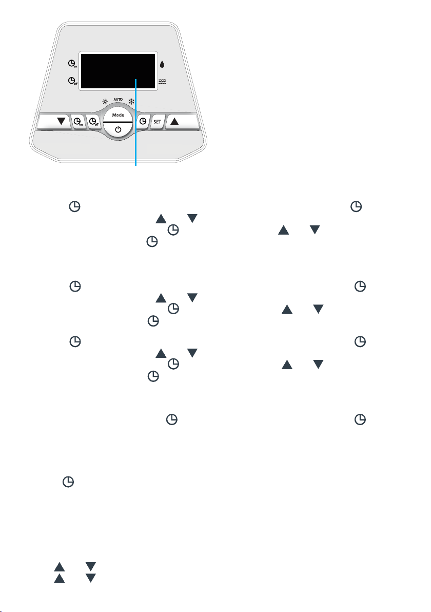
3.6 Check Current Temperature
When ON, press the “SET” button for 5 seconds and or to check the current status
of the unit. You can check the Water Temp-/Compressor protection exhaust Temp-/Heat
Copper Temp-/Return Gas Temp-/Ambient Temp-/Cooling Copper Temp-/ Actual open
steps of EE valve. If no buttons are pressed within 5 seconds, the LED will display the water
temperature. When the unit is switched OFF, the current time is displayed.
on
off
Mode
SET
offon
AUTO
on
off
Mode
SET
offon
AUTO
on
off
Mode
SET
offon
AUTO
on
off
Mode
SET
offon
AUTO
on
off
Mode
SET
offon
AUTO
on
off
Mode
SET
offon
AUTO
Water temperature
Heating copper temperature
Ambient temperature
Compression protection exhaust temperature
Return gas temperature
Cooling copper temperature
G 13
L 20
H 17
N 30
E 27 F 75
12
on
off
Mode
SET
offon
AUTO
Actual open steps of EE valve
G 70
3.7 Setting the Time
Press the button to set the time. When the time displayed blinks, press the button
again and then use the arrows and to change the hour setting.
To change the minutes, press the button again using the and arrows. Once the
correct time is set, press the button again to set. The display should return to normal.
3.8 Timer ON/OFF
Press the on button to set the time. When the time displayed blinks, press the on button
again and then use the arrows and to change the hour setting.
To change the minutes, press the on button again using the and arrows. Once the
correct time is set, press the on button again to set. The display should return to normal.
Press the off button to set the time. When the time displayed blinks, press the off button
again and then use the arrows and to change the hour setting.
To change the minutes, press the off button again using the and arrows. Once the
correct time is set, press the off button again to set. The display should return to normal.
The time setting is a 0 to 24 hours cycle.
To deactivate the timer press the button. When the display blinks, press the to
deactivate TIMER.
3.9 Coercive Defrosting
1. Press button for 5 seconds when the unit is in heating mode.
The unit will then go to defrost state.
2. When the defrosting conditions are met, defrosting will stop automatically.
3. After 30 seconds, the unit will switch to heat mode again.
3.10 Key Lock
Press and for 3 seconds, to set key lock.
Press and for 3 seconds again to release key lock.

13
4. Safety and Control Systems
Heat pumps are equipped with the following standard safety control systems:
4.1 Water Flow Switch
The water ow switch ensures that the heat pump does not work when the lter pump is
faulty (and the water is not circulating). This control system also stops the heat pump if the
water circulation is cut off or stopped.
4.2 Refrigerant Gas High-and-Low Pressure Protection
The high pressure protection system ensures the heat pump is not damaged in case of
over-pressurization of the gas. The low pressure protection emits a signal when refrigerant
is escaping from the conduits and the unit cannot function.
4.3 Overheating Protection on the Compressor
This protects the compressor from overheating.
4.4 Automatic Defrost Control
When the air is very humid and cold, ice can form on the evaporator. When this happens,
a thin layer of ice appears that will become bigger as the heat pump is running. When the
temperature of the evaporator gets too low, the automatic defrost control system will be
activated. This system will reverse the heat pump cycle so that hot refrigerant gas is sent
through the evaporator during a brief period of time to defrost it.
4.5 Anti-frost Protection During Winter
This protection can only be activated if the heat pump is in STAND-BY mode.
4.5.1 First Anti-frost Protection
If the lter pump is controlled by the heat pump (regardless of the value for parameter 9),
when the water temperature is between 2 and 4°C and the air temperature is lower than
0°C, the lter pump will be automatically turned on to prevent the water from freezing in
the piping. This protection system will deactivate automatically when the temperature rises
again.
4.5.2 Second Anti-frost Protection
If the water temperature drops even more, that is, below 2°C (during long frost periods),
the heat pump will also start running to heat the water until its temperature reaches
3°C. When this minimum temperature is reached, the heat pump will stop, but anti-frost
protection will remain active until conditions change.

14
4.6 Three Phase Protection
If the phases are connected in the wrong order due to electrical mis-wiring, this protection
system will interrupt the power supply to prevent damage to the unit. There will be an EE 4
error code on the display.
5. Installation
5.1 RecommendedAirFlowRequirements
• The series of heat pumps must be located outside in a clean area where air ow will not
be restrictive. The heat pump must be located external to the spa pool cabinet to allow
sufcient air ow for optimum efciency.
• The heat pump must operate with a clean air supply so should be situated away from
vegetation and obstacles.
WARNING: The heat pump MUST be installed according to the air space requirements
shown in Figure 1. Failure to follow these instructions may VOID WARRANTY.

15
5.2 Location of the Unit
Select a suitable location in accordance with below notes and consult the local swimming
pool safety regulations to check requirements for proximity to other equipment.
Install on wall Install on ground
Install on stand
IMPORTANT: Installation location notes
1. The heat pump must be installed on
a at, solid and large enough base to
properly secure the heat pump. Whilst
it can be mounted on brackets or stands
a level concrete base is preferred.
2. If installing the heat pump in a harsh
climatic area (i.e. sub-zero temperatures,
snow, humidity), it is recommended to
raise the unit 50cm above the ground.
3. During installation, ensure sufcient free
space is left around the heat pump for
future maintenance.
4. The unit is air cooled. It must be
installed outdoor in an area with
sufcient clearance to provide enough
air circulation through evaporator.
5. DO NOT install heat pump in a conned
space to prevent recycling of air.
6. The fan should not blow towards
windows, walls or spaces likely to be
inhabited by people or animals.
16
7. Do not install where the heat pump is likely to be subjected to polluted air, dust or
debris etc.
8. Avoid directing fan output against the dominant wind directions.
9. Protect the heat pump from possible snow fall.
10. Minimise exposure to environmental conditions as much as
possible and never block the airow.
11. Ensure the heat pump is installed in an area that is free from
ammable and corrosive chemicals, and grease.
5.3 Installation of Water Pipes
Glued Union Fittings:
1. Ensure both tail piece and locking ring are screwed/tted to the heat pump
and tightened before gluing water pipe to union tail. This will ensure the tail piece has
an even seal against the o-ring.
2. Use PVC priming uid on end of water pipe and union tails before gluing. Once primed
glue pipes into place and ensure pipes are running straight and square into heat pump.
IMPORTANT: Ensure the pipe work running from the heat pump to the spa pool
is supported. DO NOT have long runs of pipe in mid-air above the ground without
support. Ideally return the pipes to ground level as they exit the heat pump to ensure
the pipe work is self-supporting.
NOTE: Once the pipe work is full of water it will become heavy and will place strain
on the heat pump outlets if the pipe work is not supported. In the case of glued union
ttings, if the pipe work is unsupported the strain could cause stress damage to the
outlets and potential leaks. IT IS THE INSTALLER’S RESPONSIBILITY TO ENSURE
THE PIPE WORK IS ADEQUATELY SUPPORTED AND RESTRAINED TO PREVENT
MOVEMENT AND STRESS.

17
5. 4 Heat Pump Plumbing Diagram
Connection is carried out with a by-pass located on the circuit of ltration, upstream of the
chemical treatment unit.
Connect intake/outlet water PVC pipes (DN50) to the
the inlet / outlet ports as indicated (grease the threads before xing)
Swimming pool
Filter
Technical room
By-pass
Heat pump
Blowing
Chemical
Treatment

18
5.5 Electrical Connection
CAUTION: before connecting the heat pump, make sure that the main circuit is isolated
and disconnected.
All electrical connections must be performed by a licensed electrician and must conrm to
all national, state and local electrical codes in effect at the time of installation.
The heat pump must be connected to a suitable rated and weather protected power
supply. The supply line should be a dedicated power circuit and means for disconnection
must be incorporated in the xed wiring in accordance with your local wiring regulations.
Means for disconnection from the supply mains should have a contact separation in all
poles that provide full disconnection under over
Voltage Category III conditions.
Characteristics of the electric supply:
• 230 V +/- 10%, single-phase current, or 380 V +/- 10%, three-phase current,50 Hz - Mode
of neutral TT and TN.S; the circuit of heat pump must be connected to an earth circuit.
Characteristic minimum of the protection:
• Protection must be of 16 A, by circuit breaker or fuse; it must protect the Heat pump
exclusively; the circuit breaker must be specied with curve D, the fuse must be
specied Am.
• Differential protection : 30 mA (the length of cable between the connector block of the
heat pump and the circuit breaker / fuse should not exceed 12 m).
Control:
The heat pump is tted with a water ow switch which is used to signal the software card
when the water ow is sufcient.
The heat pump can also directly control ltration pump operation using a contacting relay
(not supplied). Please contact us for further information if you wish to congure the heat
pump in this way.
The recommended water ow is 5m3/h.
6. Water Flow and Refrigerating Circuit Pressure
After installation, set the pressure of the refrigerant circuit to ensure optimal operation of
the heat pump, as follows:
Stage 1:
Before starting the Heat Pump, the ambient temperature should
be around 20°C, & the refrigerant meter shows pressure between
14 - 16kg/cm2.
Stage 2:
Close the by-pass valve and open the large inlet and outlet
valves of the heat pump so that all of the water ow goes
through the heat pump.

19
Set the Heat Pump in heating mode, wait for the indicated pressure to stabilize; the correct
setting of the pressure is between 21 - 35 kg/cm2;
In most cases (where ltration pump provides a ow rate up to 9m3/h) you do not have to
open the by pass valve.
If the stabilized pressure is under 21kg/cm2, the progressive opening of the by-pass valve
will allow this pressure to increase.
When the adjustment/calibration of the by-pass valve is complete, you should not have to
further adjust it once set.
7. Problematic Environmental Conditions
Under certain conditions the heat exchanges between the refrigerant and the water and
between the uid and the air is insufcient. The consequence is that the refrigerating
circuit runs at a higher than normal pressure and the compressor consumes more
electricity.
The temperature sensors’ compressor outlet and the magnetic circuit breaker on the
compressor power supply, protect the compressor from these extreme conditions.
When this occurs the error message EE 05 is displayed.
The conditions causing this situation is as follows:
In heating mode:
• Insufcient water ow: close the by-pass valve to increase the refrigerant
exchange water.
In cooling mode:
• Excess water ow: open the by pass valve to decrease the water ow and so the
exchange water refrigerant.
• Insufcient air ow: be sure that the net of the condenser is not blocked.
Note: these error codes are likely to occur if temperature of the swimming pool water is
high and the temperature is hot.
8. Maintenance and Inspection
8.1 Maintenance
• Check the water inlet and drainage often.
The water and air inow into the system should be sufcient so that its performance and
reliability does not get compromised.
You should clean the pool lter regularly to avoid damage to the unit caused by
clogging of the lter.
• The area around the unit should be spacious and well ventilated. Clean the sides of the
heat pump regularly to maintain good heat exchange to save energy.
• Check if all aspects of the unit are operational and pay special attention to the

20
operation pressure of the refrigerant system.
• Check the power supply and cable connections regularly. Should the unit begin to
function abnormally or should you notice a smell from an electrical component, arrange
for repair or replacement.
• Winterizing : make sure to purge all the water from the heat pump and other systems in
order to prevent frost damage.
• You should also purge the water if the unit will not work for an extended period of time.
You should check all parts of the unit thoroughly and completely ll the system with
water before turning it on.
8.2 Troubleshooting Guide
Improper installation may result in an electrical discharge that could lead to death of –
or serious injury to -pool users, installers or others due to electrical shock and may also
cause damage to your property.
DO NOT attempt to modify the internal conguration of the heat pump.
• Keep your hands and hair clear of the fan blades to avoid injury.
• If you are not familiar with your pool ltering system and heat pump:
a. Do not attempt to adjust or service without consulting your dealer or your
professional pool or air conditioning contractor.
b. Read the entire installation and user manual before attempting to use, service
or adjust the unit.
c. Start the heat pump at least 24 hours after its installation in order to prevent
damage to the compressor.
Note: Switch off the power prior to maintenance or repairs.
8.3 Overview of Possible Error Codes Displayed on the Screen
Go back to chapter 4 “Protection systems” for more detailed information.
The heat pump screen displays one of the following codes:
Display Problem Cause Solution
PP 1 “WATER IN” sensor out
of order
Sensor open or short-circuited Check or replace the sensor
PP 2 “Compressor exhaust”
sensor out of order
Sensor open or short-circuited Check or replace the sensor
PP 3 “EVAPORATOR PIPE”
sensor out of order
Sensor open or short-circuited Check or replace the sensor
PP 4 “Return Gas”sensor out
of order
Sensor open or short-circuited Check or replace the sensor
PP 5 “AIR” sensor out of order Sensor open or short-circuited Check or replace the sensor
PP 6 “Condenser PIPE” sensor
out of order
Sensor open or short-circuited Check or replace the sensor
This manual suits for next models
5
Table of contents
Other SpaNet Heat Pump manuals


