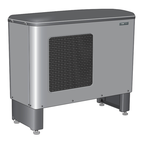
Nibe S2125 User guide

IHB EN 2125-1
431990
INSTALLER MANUAL
Air/water heat pump
NIBE S2125


41 Important information
4Safety information
4Symbols
4Marking
5Serial number
6Inspection of the installation
7
Compatible indoor modules (VVM) and control
modules (SMO)
8Indoor module
8Control module
92 Delivery and handling
9Transport
9Assembly
11Condensation
12Supplied components
13Removing the side panel and top panel
14Installation of automatic gas separator
173 The heat pump design
17General
21Distribution box
22Sensor placement
234 Pipe connections
23General
23Symbol key
24Pipe coupling, heating medium
255 Electrical connections
25General
25Accessibility, electrical connection
26Connections
316 Commissioning and adjusting
31Preparations
31Filling and venting
31Start-up and inspection
31Post adjustment and venting
32Adjustment, charge flow
337 Control
33General
33LED status
34Master control
35Control conditions
36Control - Heat pump EB101
398 Disturbances in comfort
39Troubleshooting
40Temperature sensor data
42Alarm list
459 Accessories
4610 Technical data
46Dimensions
47Sound levels
48Technical specifications
52Energy labelling
55Electrical circuit diagram
63Item register
67Contact information
3Table of ContentsNIBE S2125
Table of Contents

Safety information
This manual describes installation and service proced-
ures for implementation by specialists.
The manual must be left with the customer.
Symbols
Explanation of symbols that may be present in this
manual.
NOTE
This symbol indicates danger to person or ma-
chine .
Caution
This symbol indicates important information
about what you should consider when installing
or servicing the installation.
TIP
This symbol indicates tips on how to facilitate
using the product.
Marking
Explanation of symbols that may be present on the
product’s label(s).
The CE mark is obligatory for most products
sold in the EU, regardless of where they are
made.
CE
The UKCA mark is obligatory for most products
sold in the UK, regardless of where they are
made.
Classification of enclosure of electrical equip-
ment.
IP
Fire hazard!
Danger to person or machine.
!
Read the User Manual.
Read the Installer Manual.
NIBE S2125Chapter 1 | Important information4
1 Important information

Serial number
The serial number can be found on the rear cover and
at the bottom on the side.
Caution
You need the product's (14 digit) serial number
for servicing and support.
5Chapter 1 | Important informationNIBE S2125

Inspection of the installation
Current regulations require the heating installation to undergo an installation inspection before it is commissioned.
The inspection must be carried out by a suitably qualified person. In addition, fill in the page for information regarding
the installation data in the User Manual.
DateSigna-
ture
NotesDescription
✔
Heating medium (page 23)
Automatic gas separator installed
System flushed
System vented
Particle filter
Shut-off and drain valve
Charge flow set
Electricity (page 25)
Fuses property
Safety breaker
Earth circuit-breaker
Heating cable type/effect
Fuse size, heating cable (F3)
Communication cable connected
S2125 addressed (only when cascade
connection)
Cooling permitted
Connections
Main voltage
Phase voltage
Miscellaneous
Condensation water pipe
Insulation for condensation water
pipe, thickness (unless KVR 11 is
used)
NOTE
Check the connections, main voltage and phase voltage before the machine is started, to prevent damage
to the heat pump electronics.
NIBE S2125Chapter 1 | Important information6

Compatible indoor modules (VVM) and control
modules (SMO)
SMO S40SMO S30VVM S320
XXXS2125-8
XXXS2125-12
SMO 40SMO 20VVM 500VVM 320VVM 310VVM 225
XXXXXXS2125-8
XXXXXS2125-12
7Chapter 1 | Important informationNIBE S2125

Indoor module
VVM S320
Stainless steel, 3x230 V
Part no. 069 201
VVM S320
Stainless steel, 1x230 V
Part no. 069 198
VVM S320
Stainless steel, 3x400 V
Part no. 069 196
VVM S320
Enamel, 3x400 V
Part no. 069 206
VVM S320
Copper, 3x400 V
Part no. 069 195
VVM 310
Stainless steel, 3x400 V
With integrated EMK 310
Part no. 069 084
VVM 310
Stainless steel, 3x400 V
Part no. 069 430
VVM 320
Stainless steel, 3x230 V
Part no. 069 113
VVM 320
Stainless steel, 1x230 V
Part no. 069 111
VVM 320
Stainless steel, 3x400 V
Part no. 069 109
VVM 320
Enamel, 3x400 V
With integrated EMK 300
Part no. 069 203
VVM 500
Stainless steel, 3x400 V
Part no. 069 400
VVM 320
Copper, 3x400 V
Part no. 069 108
Control module
SMO S30
Control module
Part no. 067 637
SMO S40
Control module
Part no. 067 654
SMO 20
Control module
Part no. 067 224
SMO 40
Control module
Part no. 067 225
NIBE S2125Chapter 1 | Important information8

Transport
S2125 must be transported and stored vertically.
NOTE
Ensure that the heat pump cannot fall over
during transport.
Check that the heat pump has not been damaged during
transport.
Assembly
• Place the heat pump in a suitable location outdoors
to prevent any risk of the refrigerant flowing in through
ventilation openings, doors or similar openings in the
event of a leak. It must also not constitute a hazard
to people or property in any other way.
• If the heat pump is placed in a location where any re-
frigerant leak could accumulate, for example below
ground level (in a dip or low-lying recess), the installa-
tion must satisfy the same requirements that apply
for gas detection and the ventilation of engineering
rooms. Requirements regarding sources of ignition
must be applied where appropriate.
• Place S2125 outdoors on a solid level base that can
take the weight, preferably a concrete foundation. If
concrete slabs are used they must rest on asphalt or
shingle.
• The lower edge of the evaporator must not be lower
than the level of the average local snow depth. The
base should be at least 70 mm tall.
•S2125 should not be positioned next to noise-sensitive
walls, for example, next to a bedroom.
• Also ensure that the placement does not inconveni-
ence the neighbours.
• S2125 must not be placed so that recirculation of the
outdoor air is possible. Recirculation entails reduced
power and impaired efficiency.
• The evaporator must be sheltered from direct wind / ,
which negatively affects the defrosting function. Place
S2125 protected from wind / against the evaporator.
• A small amount of water may drip from the drainage
hole under S2125. Make sure that the water can run
away by selecting a suitable material underneath
S2125 (see section "Condensation").
• Care must be exercised so that the heat pump is not
scratched during installation.
LEK
S2125
LEK
S2125
LEK
S2125
min 300 mm
min
70 mm
Do not place S2125 directly on the lawn or other non
solid surface.
If there is a risk of snow slip from roof, a protective roof
or cover must be erected to protect the heat pump,
pipes and wiring.
9Chapter 2 | Delivery and handlingNIBE S2125
2 Delivery and handling

LIFT FROM THE STREET TO THE SET UP
LOCATION
If the base allows, the simplest thing is to use a pallet
truck to move the S2125 to the set up location.
NOTE
The centre of gravity is offset to one side (see
print on the packaging).
LEK
C:a 180 kg
Approx. 180 kg
If S2125 needs to be transported across soft ground,
such as a lawn, we recommend using a crane truck that
can lift it to the installation location. When S2125 is lifted
with a crane, the packaging must be untouched.
If a crane vehicle cannot be used the S2125 can be
transported on an extended sack truck. S2125 must be
taken from its heaviest side and two people are required
to lift S2125.
LIFT FROM THE PALLET TO FINAL
POSITIONING
Before lifting remove the packaging and the securing
strap to the pallet.
Place lifting straps around each machine foot. Lifting
from the pallet to the base requires four persons, one
for each lifting strap.
SCRAPPING
When scrapping, the product is removed in reverse or-
der. Lift by the bottom panel instead of a pallet!
NIBE S2125Chapter 2 | Delivery and handling10

INSTALLATION AREA
The distance between S2125 and the house wall must be at least 350 mm, but not more than 500 mm in locations
that are exposed to the wind. The free space above S2125 must be at least 1,000 mm. The free space in front
must be at least 1,000 mm for any future servicing.
350 mm
Fritt utrymme bakom
Fritt utrymme framför
dock 1000 mm för ev. framtida service
Min. avstånd
vid användning
av flera F2300
600 mm
1000 mm
400 mm
Minimalt
fritt utrymme
600mm
Minimalt
fritt utrymme
Minimum free
space Minimum free space
Minimum distance during use
of several S2125
600 mm
600 mm
At least 1,000
mm
400 mm
Free space in front for any future servicing
350 – 500 mm Free space behind*
* The space behind must not exceed 500 mm in locations that are exposed to the wind.
Condensation
The condensate drain pan collects and leads away the
condensation water.
NOTE
It is important to the heat pump function that
condensation water is led away and that the
drain for the condensation water run off is not
positioned so that it can cause damage to the
house.
Condensation run-off should be checked regu-
larly, especially during the autumn. Clean if
necessary.
• The condensation water (up to 50 litres/24 hrs) that
collects in the trough should be routed away by a pipe
to an appropriate drain, it is recommended that the
shortest outdoor stretch possible is used.
• The section of the pipe that can be affected by frost
must be heated by the heating cable to prevent
freezing.
TIP
Pipe with heating cable for draining the con-
densation water trough is not included.
To ensure the function, the accessory KVR 11
should be used.
• Route the pipe downward from S2125.
• The outlet of the condensation water pipe must be at
a depth that is frost free or alternatively indoors (with
reservation for local ordinances and regulations).
• Use a water trap for installations where air circulation
may occur in the condensation water pipe.
• The insulation must seal against the bottom of the
condensation water trough.
11Chapter 2 | Delivery and handlingNIBE S2125

DRAINAGE OF CONDENSATION
Stone caisson
LEK
Frostfritt djup
S2125
Frost proof depth
If the house has a cellar the stone caisson must be po-
sitioned so that condensation water does not affect the
house. Otherwise the stone caisson can be positioned
directly under the heat pump.
Drain indoors
Water seal
The condensation water is lead to an indoor drain (sub-
ject to local rules and regulations).
When routing pipes indoors, condensation water pipes
must be insulated against condensation.
Route the pipe downward from S2125.
The condensation water pipe must have a water seal to
prevent air circulation in the pipe.
Pipe routing indoors is not included.
Gutter drainage
LEK
S2125
Frostfritt
djup
Frost free
depth
Water seal
Route the pipe downward from S2125.
The condensation water pipe must have a water seal to
prevent air circulation in the pipe.
Caution
If none of the recommended alternatives is
used good lead off of condensation water must
be assured.
Supplied components
1 x filterball (G1")
2 x flexible pipes (DN25,
G1") with 4 x gaskets
1 x non-return valve
1 x automatic gas separat-
or
NIBE S2125Chapter 2 | Delivery and handling12

Removing the side panel and top panel
Undo the screws, lift off the top panel and the top insulation.
LEK
13Chapter 2 | Delivery and handlingNIBE S2125

Installation of
automatic gas
separator
1. Check that all O-rings are present and that they are
undamaged. Lubricate them with soapy water or
similar to make installation easier.
Press the gas separator into place. Fit the clip. Twist
the clip to ensure that it fastens properly.
Place the bracket in position, parallel with the outer
edge. Secure the bracket with a screw. Use a
socket wrench, size 10 mm.
2. Assemble the parts of the safety valve. Ensure that
the arrow for the outlet is pointing down, as illus-
trated.
3. Then fit the safety valve with the associated pipes.
The safety vale must be at an angle of 45°. Fit the
clip. Twist the clip to ensure that it fastens properly.
45º
4. Install the non-return valve. Fit the clip. Twist the
clip to ensure that it fastens properly.
NIBE S2125Chapter 2 | Delivery and handling14

5. Place on the right-hand half of the metal box. The
lug in the insulation must go into the round hole in
the bracket.
6. Fit the left-hand half in the same way.
7. Check that both halves of the gas separator are
properly in place, parallel with the edge of the heat
pump.
8. Put the lid on. Secure with three screws. Two
screws in the lid, on the right and left-hand sides,
and one screw in the bottom.
15Chapter 2 | Delivery and handlingNIBE S2125

9. Secure the gas separator to the heat pump using
two screws, one at the top and one at the bottom.
10. Install the lid that conceals the safety valve.
11. Screw the flexible pipes into place. The flexible pipes
can be installed angled straight back or down, de-
pending on which of the pipe connections the 90°
bend is installed on. Install the flexible pipes with a
slight bend, so they can absorb any vibrations that
would otherwise be propagated through the building.
NOTE
Don’t forget the flat gaskets.
12. Check that there is an opening in the insulation, to
allow any liquid and gas from the safety valve and
the gas separator to escape.
NIBE S2125Chapter 2 | Delivery and handling16

General
S2125 (1x230V)
GQ1
AA2
UB1
BT12
EP2
XL1
BT3
XL2
HS1
XL21
BT84
QN4
RM1.1
QN2
QN1
BT17
BT14 EB10
QA40 GQ10RA1X6
BP9
BP1
BP2
BP8
XL20
HQ9
BT15
CA1 FQ14
17Chapter 3 | The heat pump designNIBE S2125
3 The heat pump design

S2125 (3x400V)
GQ1
AA2
UB1
BT12
EP2
XL1
BT3
XL2
HS1
XL21
BT84
QN4
RM1.1
QN2
QN1
BT14 EB10
QA40 GQ10RF2RA1
BP9
BP1
BP2
BP8
XL20
HQ9
BT17BT15
PF1 FQ14
AA13
NIBE S2125Chapter 3 | The heat pump design18

Serie nr.
Data label
PZ4
BT16
PZ1
BT28
EP1
WM5
XL40
XL1XL2
PZ3
PZ3
UB1
RM1.2
HQ8
FL2
19Chapter 3 | The heat pump designNIBE S2125

PIPE CONNECTIONS
Connection, heating medium out of S2125XL1
Connection, heating medium in to S2125,XL2
Service connection, high pressureXL20
Service connection, low pressureXL21
Connection, drain condensation water troughXL40
HVAC COMPONENTS
Safety valve, heating mediumFL2
Automatic gas separatorHQ8
Non-return valveRM1.2
Condensation water troughWM5
SENSORS ETC.
High pressure pressostatBP1
Low pressure pressostatBP2
Low pressure transmitterBP8
High pressure sensorBP9
Temperature sensor, returnBT3
Temperature sensor, condenser supply lineBT12
Temperature sensor, hot gasBT14
Temperature sensor, fluid pipeBT15
Temperature sensor, evaporatorBT16
Temperature sensor, suction gasBT17
Temperature sensor, ambientBT28
Temperature sensor, suction gas evaporatorBT84
ELECTRICAL COMPONENTS
Base cardAA2
Triac boardAA13
Capacitor (1x230V)CA1
Compressor heaterEB10
Temperature limiter, compressorFQ14
FanGQ1
Signal lamp (LED 201)PF1
InverterQA40
Harmonic filter (3x400V)RA1
Choke (1x230V)RA1
EMC filter (3x400V)RF2
Terminal block (1x230V)X6
COOLING COMPONENTS
EvaporatorEP1
CondenserEP2
CompressorGQ10
Particle filterHQ9
Drying filterHS1
Expansion valveQN1
4-way valveQN2
Bypass valveQN4
Non-return valveRM1.1
MISCELLANEOUS
Type platePZ1
Serial numberPZ3
Sign, pipe connectionsPZ4
Cable gland, incoming supplyUB1
Designations according to standard EN 81346-2.
NIBE S2125Chapter 3 | The heat pump design20
Other manuals for S2125
5
Table of contents
Other Nibe Heat Pump manuals

Nibe
Nibe F2300 User manual

Nibe
Nibe AMS 10 Series User guide

Nibe
Nibe F1126 User manual

Nibe
Nibe AP-BW30 User manual

Nibe
Nibe F470 User guide

Nibe
Nibe F1255 Series User manual

Nibe
Nibe F110 User manual

Nibe
Nibe FIGHTER 1250 Operating and maintenance instructions

Nibe
Nibe F1255 Series User guide

Nibe
Nibe F1145 series Quick start guide
Popular Heat Pump manuals by other brands

Carrier
Carrier 38AKS013-024 Wiring diagrams

Weil-McLain
Weil-McLain WM2AC13018 Installer's information manual

Hitecsa
Hitecsa EKWXBA HE 38.2 Installation, operation & maintenance manual

Sinclair
Sinclair STHERM GSH-60IRB Service and installation manual

Mark
Mark MISTRAL MDX 33 Technical manual

Daikin
Daikin RTSQ20PY1 Service manual