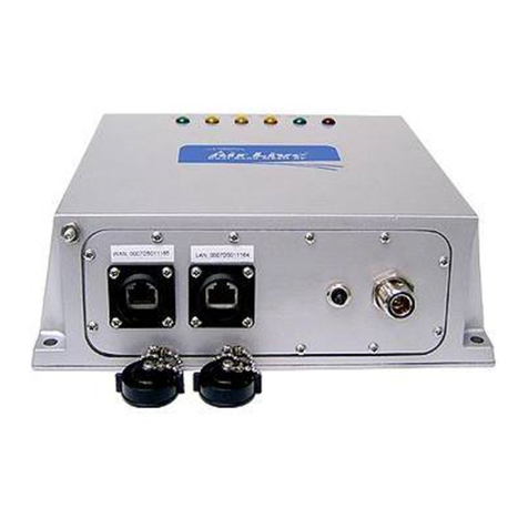
Sparklan OA200 User manual

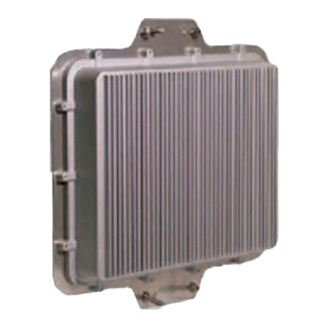
OA200 Outdoor 802.11ag AP
Quick Installation Guide
Version1.0

Content
1. Introduction..........................................................3
2. Operating Mode....................................................4
3.HardwareInstallation...........................................6
4. QuickSetup Guide...............................................11
5.WaterproofRJ-45ConnectorAssembly...........15

3
1.Introduction
1.1Purpose
Thisdocumentprovidesinformationandproceduresonhardwareinstallation,
setupandmanagementofthe IEEE 802.11ag APBridge.
1.2Overview
Access PointwithRuggedHousingforApplication
OA200Wireless11agAP Bridge providesqualityconnectivityfor
Wi-Finetworks. Thisdeviceisidealforrugged environmentsand
application.
MultipleOperatingModes
OA200 Wireless11ag AP Bridgeprovides3operating modes.Thereare
AP,AP RepeaterandWireless Client.When itissettoAP mode, itconnects
wirelessclientstoawired network.InAP Repeatermode,itcanextendthe
communication distanceofwireless connection.Finally,inWireless Wireless
client mode,AP autoscan forspecificAP (remoteAP'sSSID), then set up
connection toit asaclient.
Wi-Fi CompliantDevice
OA200isWi-Ficompliantdevicewhichensuresthe networkcompatibility.
HighPerformanceforWireless Coverage
OA200designstosupportlargeareas.Thisunitisbuilt-inhighpowerRF
module.
Installation
OA200 isveryeasytoinstall andset up. PoweroverEthernet support offers
the powerforthisunit and decreasesmost effort on installation.

4
2.Operating Mode
OA200provides3kindsofoperatingmodeforapplication.
AP mode
AP Repeatermode
WDSmode
2.1AP mode
InAPmode,it can connect multiplewireless clientstoawirednetwork.
2.2AP Repeatermode
AP Repeatermode allowsOA200tocommunicatewithother802.11agAPs
whilefunctioninginAP mode,andtoextendyourWireless Networkcoverage.
It isset bySSID

5
2.3WDSmode
Inthismode,itallowswireless connection between twoormorewiredand
wirelessnetworks,suchastwonetworks withthe samesub-networkin
different buildings.Forbuilding-to-buildingwirelessconnection,eachbuilding
shouldimplementoneOA200asWDS.Inthiscase,theOA200 can actasa
wirelessbridgebetweenthetwowired and wireless networks.Pleasefill in
remoteAP sMACaddressin “WDSlinks”space.
2.4Wireless Client mode
AP autoscan forspecificAP (remoteAP'sSSID), then set up connectiontoit as
aclient.

6
3.HardwareInstallation
3.1LEDDescription
Thereare3LEDson therightsideofOA200.
1.LInkLED
Off:NoLANconnectionavailable
On: LANconnectionOK
2.11gLED
Off: noactivity
Blinking: sendingandreceivingdata
3.11aLED
Off:no activity
Blinking: sendingandreceivingdata

7
3.2MountKit Installation
1.Assemblepart
1
ofthe mountkitatthe rearofOA200,showninthe above
figure.
2.IfyouaremountingtheAccessPointonawall,firstinstall thebracket
2
of
themounting kittoasuitableposition.Assemblethebackofthe OA200
housingtothebracketsubsequently.
3. Ifyou aremountingtheOA200toapole,firstinstall the bracket
2
andtheclip
3
ofthemountingkittoastrong pole.Assembletherearofthe OA200
housingtothebracketsubsequently.
4.Insert the LANcabletoaPoweroverEthernet socket. Makesurethepower
LEDandLANlinkLEDislightup.

8
3.3PoweroverEthernet Installation
1. Connect the Ethernet cablefromtheOA200toPoEhub(LANout).
2. Connect asecondEthernet cablefromthe LAN-INportof the PoEadapterto
afreeportofaswitchorhub withinthelocalnetwork.Pleaserefertothe
abovefigure.

9
3.4HardwareReset todefault settings
Youcanresetthewirelessbridge unit ssettingstofactorydefaultsbypushing
resetbutton usingreset bar.The resetbutton islocatedand hiddeninsideofthe
rearpanelasabovefigure.Pleaserefertothefollowing stepstoperformthe
HardwareReset.

10
1. Pleaseunscrewthescrewpart asabovefigure.
2. Pleaseusetheresetbartoreachtheresetbutton.Pressitandholdonfor
approx10seconds.
3.Releasethe resetbutton,thedevicewill rebootandall configurationswill be
set tofactorydefault settingsautomatically.
3.5
Antenna installation onOA200
antennainsidebox,sotheexternalantenna isnecessaryforthisunit. Please
find theRP-SMA Antenna connectorontherearsideofthisbox.Usually,itshouldbea
lowloss RFcableconnected between OA200Nand antenna.
Fordecreasethesignalloss,westronglysuggestusingRFcablewithhigh
qualityand the lengthshouldbe asshortaspossible. TherearetwoRP-SMA types
connectorattherearside. OneisAntenna1,theotherisAntenna2
OA200 is one 11ag AP series with external antenna.The cable with male to male
N-type connector will be use to connect withOA-200 physical utility. The cable
with female to female reverse N-type connector shall be used as extension cable
to establish connection with RSMA converter, The Antenna will be connecting to
RSMA converter.

11
4.QuickSetup Guide
APDefaultSettings
Thedefaultsettingsareshown asthefollowing:
User
Password admin
IPAddress 192.168.1.250
SubnetMask
255.255.255.0
RFESSIDAband:wlan-aGband:wlan-g
Channel Aband:AutoGband:6
Mode Gband:Mixed
Encryption Disabled

12
Step1
STARTUP &LOGIN
InordertoconfiguretheOA200, youmust useyourweb browserand manually
input http://192.168.1.250 intothe AddressBoxandpressEnter.The Main
Pagewillappear.
TostartconfiguretheOA200,youmustinputpassword “admin”onthe
passwordsection.
Onceyouhavelogged-inasadministrator,itisidealtochange the
administratorpasswordtoensureasecureprotection tothe Wireless11agAP.
PleaserefertotheSecuritySettingsinthe latersection, whichdescribeshowto
changethe password.
Onceyouhaveinputthe correctpasswordandlogged-in,the screenwill
changetotheSetup pagescreen.

13
Step2
LocalArea Network:ThisisOA200IPAddress andSubnet Maskas
seen on theinternalLAN.The defaultvalueis192.168.1.250 forIP
Address and255.255.255.0forSubnet Mask.
PleaseClick Apply”buttontosaveyoursettingsonceyouhaveanychange.

14
Step3
Pleaseselect theantennaforeachband.
Aftercompleted thesettingand hardwareinstallation,pleaseadjustthe
direction ofOA200 toremotesiteOA200 forahigh qualitytransmission.

15
5. WaterproofRJ-45ConnectorAssembly
Recommendation:
Pleaseprepareone CAT-5orbetterqualityEthernetcablethengetthroughthe
partsof waterproof connectorbeforethisassembly.

16
The equipmenthasbeen tested and found tocomplywithFCC and CERules.Operation is
subject tothe following twoconditions:
(1)Thisdevicemaynotcauseharmfulinterference.
(2)Thisdevicemust accept anyinterferencereceivedincluding interferencethat may
causeundesired operation.
REMARK: 5150MHz~5250MHz, 5250MHz ~ 5350MHz frequency will be disabled by
firmware.

17
FederalCommunicationCommissionInterference Statement
ThisequipmenthasbeentestedandfoundtocomplywiththelimitsforaClassB
digitaldevice, pursuanttoPart15oftheFCC Rules.Theselimitsaredesignedto
providereasonableprotectionagainstharmfulinterference inaresidentialinstallation.
Thisequipmentgeneratesusesandcanradiateradiofrequencyenergyand,ifnot
installedandusedinaccordance withtheinstructions,maycauseharmfulinterference
toradiocommunications.However, thereisnoguarantee thatinterference willnot
occurinaparticularinstallation.Ifthisequipmentdoescauseharmfulinterference
toradioortelevisionreception, whichcanbedeterminedbyturningtheequipmentoff
andon, theuserisencouragedtotrytocorrecttheinterferencebyoneofthe
followingmeasures:
-Reorientorrelocatethereceiving antenna.
-Increasetheseparationbetweentheequipmentandreceiver.
-Connecttheequipmentintoanoutletonacircuitdifferentfromthattowhich
thereceiverisconnected.
-Consultthedealeroranexperiencedradio/TVtechnicianforhelp.
Thisdevice complieswithPart15oftheFCC Rules. Operationissubjecttothe
followingtwoconditions:(1)Thisdevice maynotcauseharmfulinterference, and(2)
thisdevice mustacceptanyinterference received,including interference thatmay
causeundesiredoperation.
FCC Caution:Anychangesormodificationsnotexpresslyapprovedbytheparty
responsibleforcompliance couldvoidtheuser'sauthoritytooperatethisequipment.
IMPORTANTNOTE:
FCC RadiationExposureStatement:
ThisequipmentcomplieswithFCCradiationexposurelimitssetforthforan
uncontrolledenvironment.Thisequipmentshouldbeinstalledandoperatedwith
minimumdistance 20cmbetweentheradiator&yourbody.
Thistransmittermustnotbeco-locatedoroperating inconjunctionwithanyother
antennaortransmitter.
TheOA200 (FCCID:RYK-OA200 )islimitedinCH1~CH11for2.4GHzby
specifiedfirmwarecontrolledinU.S.A.
Table of contents

