Sparta AS-30B User manual
SPARTA
AS-3OB
AUDIO
CONSOLE
TECHNICAL
MANUAL
AS-30B
CONSOLE
SPECIFICATIONS
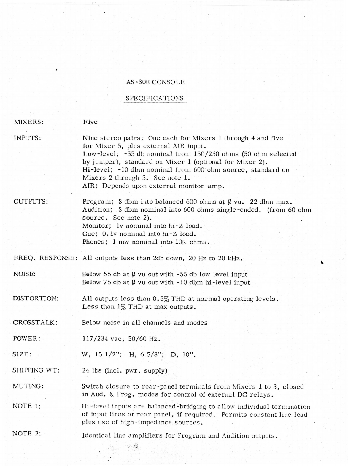
MIXERS:
Five
INPUTS:
OUTPUTS:
Nine
stereo
pairs;
One
each
for
Mixers
1
through
4
and
five
for
Mixer
5,
plus
external
AIR
input.
Low-level;
-55
db
nominal
from
150/250
ohms
(50
ohm
selected
by
jumper),
standard
on
Mixer
1
(optional
for
Mixer
2).
Hi-level;
-10
dbm
nominal
from
600
ohm
source,
standard
on
Mixers
2
through
5.
See
note
1.
AIR;
Depends
upon
external monitor-amp.
Program;
8
dbm
into
balanced
600
ohms
at
0
vu.
22
dbm
max.
Audition;
8
dbm
nominal
into
600
ohms
single-ended,
(from
60
ohm
source.
See
note
Monitor;
Iv
nominal
into
hi-Z
load.
Cue;
0.
lv
nominal
into
hi-Z
load.
Phones;
1
mw
nominal
into
10K
ohms.
FREQ.
RESPONSE:
All
outputs
less
than
2db
down,
20
Hz
to
20
kHz.
NOISE:
DISTORTION:
CROSSTALK:
Below
65
db
at
0
vu
out
with
-55
db
low
level
input
Below
75
db
at
0
vu
out
with
-10
dbm
hi-level
input
All
outputs
less
than
0.5%
THD
at
normal
operating
levels.
Less
than
1%THD
at
max
outputs.
Below
noise
in
all
channels
and
modes
POWER:
SIZE:
SHIPPING
WT:
MUTING:
NOTE
;1:
117/234
vac,
50/60
Hz.
W,
15
1/2";
H,
6
5/8";
D,
10".
24
lbs
(incl.
pwr.
supply)
Switch
closure
to
rear-panel
terminals
from
Mixers
1
to
3,
closed
in
Aud.
&
Prog,
modes
for
control
of
external
DC
relays.
Hi-level
inputs
are
balanced-bridging
to
allow
individual
termination
of
input
lines
at
rear
panel,
if
required.
Permits
constant
line
load
plus
use
of
high-impedance
sources.
NOTE
2:
Identical
line
amplifiers
for
Program
and
Audition
outputs.

SPARTA
ELECTRONIC
CORPORATION
Dear
Customer,
Careful
attention
to
Quality
Control
is
another
important
element
in
our
daily
effort
to
provide
you
with
excellence
of
product
and
service.
At
SPARTA
each
piece
of
equipment
and
sub-assembly
receives
numerous
inspections
and
tests
in
the
process
of
production.
The
final
results
must
measure
within
our
exacting
requirements
before
it
is
shipped
to
you.
Listed
below
are
just
a
few
of
the
major
check
points
and
tests
this
particular
piece
of
equipment
has
received
before
being
prepared
for
shipment.
Should
you
note
any
discrepancy
in
the
appearance
or
operation
of
your
SPARTA
Products
or
if
you
have
any
general
comments
as
to
how
we
might
be
of
greater
service,
your
suggestions
will
be
greatly
appreciated.
AS-3
OB
Customer
\
SERIAL
NO.
2-f/
DATE:
/^
"
r
^
PWR.
SUP.
SERIAL
NO:
(p
/
CAL.
BY
No<
0F
PREAMPS
OUTPUT
DISTORTION
SIGNAL/NOISE
PHASE
CH-1L:
+
^dbm
r
/
b
db
CH-1R:
+
dbm
,
/
y
£
/
db
<
CH-1L
Freq.
Resp.
-2db
at
Hz
-2db
at
KHz
CH-IR
Freq.
Resp.
-2dfa
at
Hz
-2db
at
"
KHz
MONO-STEREO
MIC.R
&
L
MONO-STEREO
OUT
CROSSTALK
CH-2L
+
^
dbm
*
/
%
/f
db
CH-2R
+
9,~
dbm
,
/
>-•
~
"
Freq.
Resp.
CH-2L
/
CH2~R
/bf
Level
?
CH-3
L
+
dbm
,
JL
CH-3
R
+
%
~dbm
,
/
%
-
/
y
~db
Freq.
Resp.
CH-3L
z'.Q ~
2
cf
K
CH-4
L
+
-
dbm
_
,
/
Z.
db
f
CH-4R
+
dbm
A
Freq.
Resp.
CH-4L
If
—
%
\
CH-5
L
A
Th.
E
+
f
dbm
,
)•?
%
-
db
^
CH-5
R
A
Th.
E
-t-
V"
dbm
Freq.
Resp.
CH-5L
y^Q
-^.71
f
Audition
L
+
"f>dbm
t
f
db
Output
R
+
yjdbm
/
Q
%
nr
db
CH2-R
f
%
db
%
?
v
db
CH3-R
%
?
f
db
%
7
db
CH4-R
/
<2
%
9~-
db
%
&
db
CH5-R
/
%
db
%
7/
db
Monitor
Air
R
&
L
Prog
R
&
L
Aud
R
&
L
Pl"I
ONE
u
CUE
^
MUTING
ASC-305B
TEP-3S
Wow
&
Flutter
RTT
LTT
Calib
by
Cart.
3/29/71

AS-3OB
CONSOLE
DESCRIPTION
GENERAL:
The
AS-30B
is
a
desk-type
Stereo
Audio
Console
featuring
five
mixing
channels
with
push-button-selected
multiple
inputs
for
Mixer
5.
As
normally
supplied,
the
first
mixer
includes
low-level
preamplifiers
for
50
to
150
ohm
microphones
and
the
remaining
four
are
supplied
with
high-level
balanced
input
transformers.
The
input
transformers
for
Mixer
1
are
located
on
cards
to
allow
replacement
with
another
pair
of
low-level
preamplifiers.
The
high-level
inputs
are
balanced
bridging,
which
avoids
the
source
loading
of
the
typical
600
ohm
input
and
greatly
increases
the
flexibility
of
the
console.
In
the
very-
rare
instance
where
a
600
ohm
termination
is
required,
it
is
a
simple
matter
to
add
a
pair
of
620
ohm
resistors
across
the
line
at
either
the
source
or
load
end.
Some
sources,
such
as
Ampex
and
TEAC,
provide
for
this
internally.
When
operating
from
sources
intended
for
single-ended,
high-impedance
loads,the
minus
input
terminals
of
the
consoles
are
connected
to
the
shield
and
the
console
now
appears
as
a
single-ended
high-impedance
(10K)
load.
The
Audition
and
Program
Amplifiers
in
the
AS-30B
are
identical
and
interchangeable.
In
the
Audition
side,
the
line-amplifier
gain
is
determined
by
internal
resistors
and
is
set
to
provide
approximately
the
same
level
output
as
the
Program
side
with
normal
gain
control
settings.
The
audition
output
terminals
are
fed
directly
from
the
audition
line
amplifiers
from a
single-ended
source
impedance
of
60
ohms.
The
audition
out-
put
is
then
capable
of
driving
multiple
loads
with
little,
if
any
attenuation.
The
input-source
selection
for
Mixer
1
is
via
a
push-button
assembly
which
allows
more
than
one
source
to
be
selected
simultaneously.
This
feature,
if
used
judiciously,
will
permit
more
tiian
one
source
to
be
mixed
simultaneously
on
the
one
mixer pot.
If
this
is
attempted,
the
individual
source
levels must
be
adjusted
externally
but
the
console
will
not
load
either
source.
It
must
be
considered,
however,
that
each

AS-30B
Description
(cont'd)
of
two
sources
will
then
be
loaded
by
die
other,
and
suitable
isolation
must
be
provided,
if
required.
INSTALLATION:
Input
and
Output
Connections,
with
the
exception
of
die
Mixer
1
XLR
connectors,
are
made
via
rear-panel
barrier
strips.
Spade
lugs
or
fanning-strips
are
not
required
since
the
barrier
strips
are
designed
with
captive
plates
to
easily
accommodate
several
stripped
wires
per
terminal,
either
solid
or
stranded.
Rear
panel
connections
are
clearly
identified
to
facilitate
installation
without
resorting
to
die
manual
or
to
a
numbered
diagram.
Audio
connections
are
normally
made
with
twisted-pair,
shielded
cable
such
as
Belden
8737
(stranded)
or
8739
(solid).
Either
may
be
used,
although
it
is
generally
more
satisfactory
to
use
solid
wire
in
a
permanent
installation
where
flexibility
is
not
required
since
solid
wire
is
easier
to
handle
and
less
apt
to
inadvertently
short
to
an
adjacent
terminal.
Single-ended
outputs
and
inputs
can
use
die
same
type
cable
by
simply
clipping
off
die
unused
conductor.
The
input
terminals
include
a
ground
connection
for
the
cable
shield
and
die
transformer
input windings
are
ungrounded
or
"floating".
This
prevents
the
possibility
of
setting
up
a
severe
ground-loop
and
also
permits
one
side
of
the
transformer
input
to
be
grounded
for
single-ended
operation
if
desired.
In
like
manner,
die
program
line
outputs
are
also
isolated.
A
central
ground
lug
is
provided
on
the
rear
panel
for
connection
to
the
system
master
ground,
and
as
heavy
a
guage
strap
or
braid
as
practical
should
be
used.

CIRCUIT DESCRIPTION,
SPARTA
AUDIO
CONSOLES
GENERAL
.
The
description
to
follow
is
generally
applicable
to
all
SPARTA
consoles,
mono
or
stereo,and
outlined
the
basic
system
of
selecting,
mixing
and
amplifying
the
usual
program-sources
plus
the
methods
used
to
process
auxilliary
functions
such
as
cue
and
monitor
signals.
Features
applicable
to
specific
consoles
are
then
discussed
elsewhere
in
the
appropriate
manual
sections.
Microphone
Preamplifiers.
With
a
nominal
gain
of
55db.
the
output
level
from
the
preamp
to
the
mixer
potentiometer
is
typically
-10
to
0dbm.
depending,
of
course,
on
the
sound
level
and
microphone
used.
In
a
normal
situation,
then,
the
preamplifier
output
is
at
essentially
the
same
level
as
the
high-level
input
signals,
resulting
in
approximately
the
same
mixer-level
settings
for
normal
operation.
Preamp
gain
can
be
changed
to
accommodate
unusual
situations
by
referring
to
the
preamplifier
circuit
description.
As
normally
supplied
by
SPARTA,
the'input
transformer
is
wired
for
use
with
150/250
ohm
microphones.
A
transformer
tap
is
provided
for
easy
conversion
to
use
with
30/50
ohm
microphones.
All
SPARTA
Audio
Consoles
are
supplied
as
standard
with
a
microphone
preamplifier
in
the
first
mixer
position.
The
preamplifiers
are
interchange
able
with
high-level
input
cards,
however,
so
additional
microphone
1.
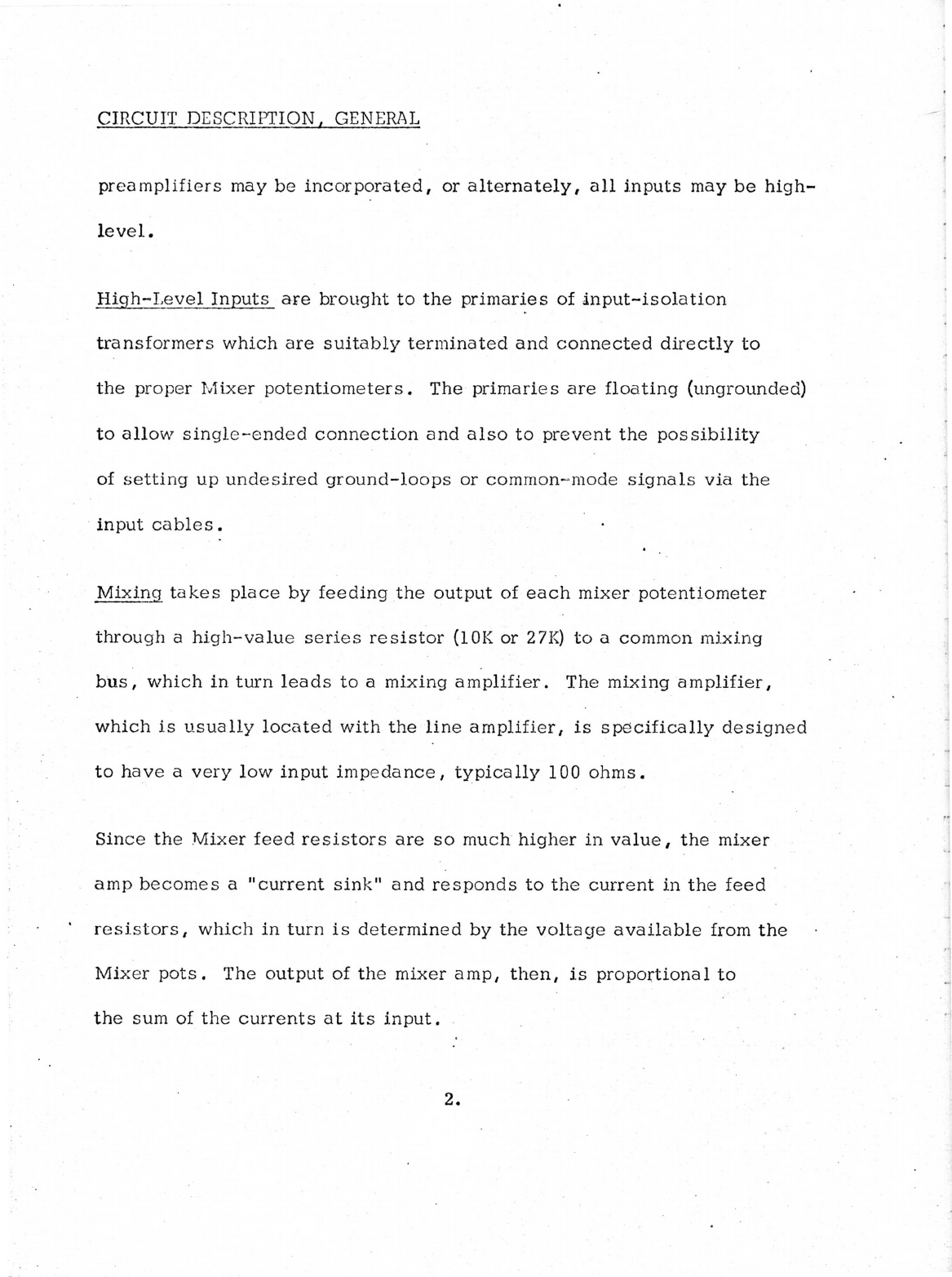
CIRCUIT
DESCRIPTION,
GENERAL
preamplifiers
may
be
incorporated,
or
alternately,
all
inputs
may
be
high-
level.
High-Level
Inputs
are
brought
to
the
primaries
of
input-isolation
transformers
which
are
suitably
terminated
and
connected
directly
to
the
proper
Mixer
potentiometers.
The
primaries
are
floating
(ungrounded)
to
allow
single-ended
connection
and
also
to
prevent
the
possibility
of
setting
up
undesired
ground-loops
or
common-mode
signals
via
the
input
cables.
•
Mixing
takes
place
by
feeding
the
output
of
each
mixer
potentiometer
through
a
high-value
series
resistor
(10K
or
27K)
to
a
common
mixing
bus,
which
in
turn
leads
to
a
mixing
amplifier.
The
mixing
amplifier,
which
is
usually
located
with
the
line
amplifier,
is
specifically
designed
to
have
a
very
low
input
impedance,
typically
100
ohms.
Since
the
Mixer
feed
resistors
are
so
much
higher
in
value,
the
mixer
amp
becomes
a
"current
sink"
and
responds
to
the
current
in
the
feed
resistors,
which
in
turn
is
determined
by
the
voltage
available
from
the
Mixer
pots.
The
output
of
the
mixer
amp,
then,
is
proportional
to
the
sum
of
the
currents
at
its
input.

CIRCUIT
DESCRIFHON.
GENERAL
Mixer
isolation
is
excellent
with
this
system
since
the
current
from
each
feed
resistor
will
follow
the
easiest
path
—
obviously
into
the
mixer
amp
rather
than
to
another
Mixer
pot.
Changing
one
mixer-pot,
then,
will
have
relatively
little
effect
upon
the
program
level
coming
from
another
mixer-pot.
There
is
obviously
a
significant
loss
of
program
power
in
the
mixer
feed
resistors,
but
the
power
levels
are
so
low
that
it
is
a
simple
matter
to
recover
the
loss
in
the
mixer
amplifier.
Mixer
amp.
gain
is
set
to
restore
the
program
to
substantially
the
same
level
as
originally
fed
to
the
mixer
pots
,
with
the
mixer-pots
at
their
usual
operating
positions,
about
one
o'clock.
Since
a
"current"
mixer
operates
from
a
relatively
high
source
impedance,
it
allows
the
use
of
high
impedance
mixer-pots.
And
since
it
is
not
critical
of
the
precise
source
impedance, there
is
no
need
to
resort
to
the
bulk
and
cost
of
precision
ladder
attenuators.
Output
of
the
mixer
system
is
then
fed
to
the
Master
gain
control
at
essentially
the
same
level
as
the
original
high-level
program
material.
To
test
the entire
mixer
system,
a
-10
or
dbm
signal
is
provided
at
a
high-level
input,
the
appropriate
mixer
pot
is
set
at
the
normal
operating
position
and
the
signal
is
viewed
or
measured
across
the
Master
gain
control.
3.
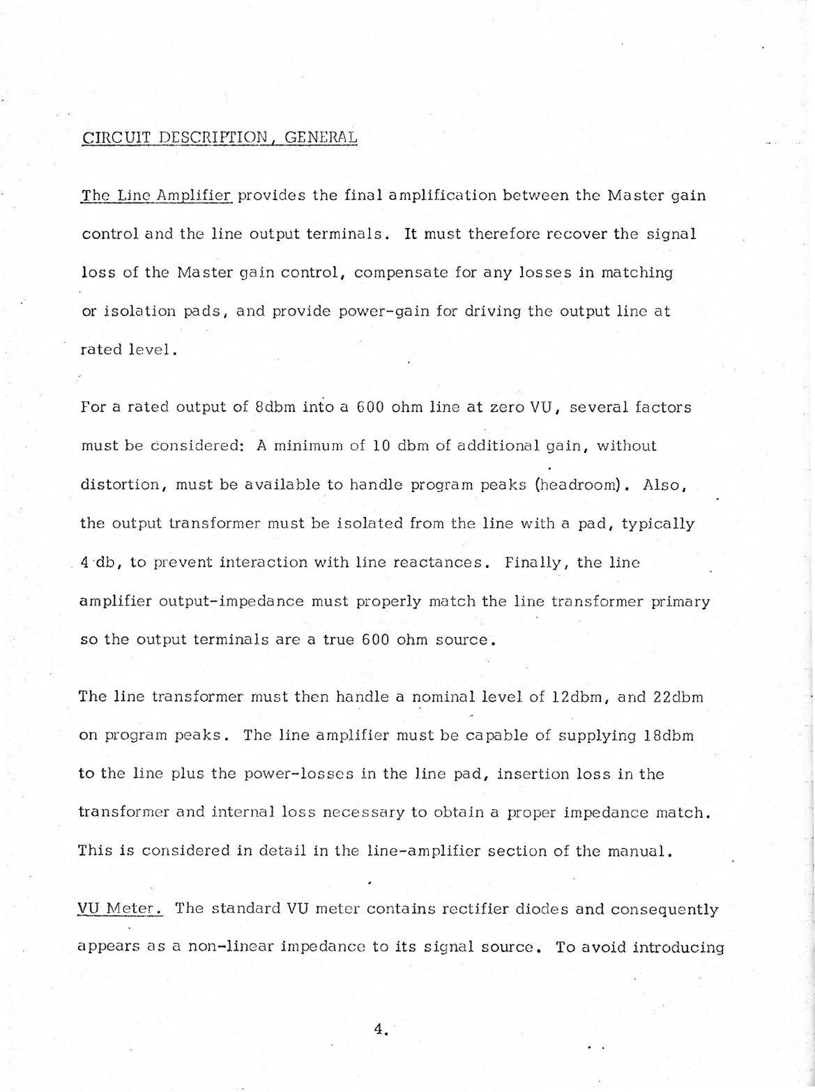
CIRCUIT
DESCRIPTION,
GENERAL
The
Line
Amplifier
provides
the
final
amplification
between
the
Master
gain
control
and
the
line
output
terminals.
It
must
therefore
recover
the
signal
loss
of
the
Master
gain
control,
compensate
for
any
losses
in
matching
or
isolation
pads,
and
provide
power-gain
for
driving
the
output
line
at
rated
level.
For
a
rated
output
of
8dbm
into
a
600
ohm
line
at
zero
VU,
several
factors
must
be
considered:
A
minimum
of
10
dbm
of
additional
gain,
without
distortion,
must
be
available
to
handle
program
peaks
(headroom).
Also,
the
output
transformer
must
be
isolated
from
the
line
with
a
pad,
typically
4
db,
to
prevent
interaction
with
line
reactances.
Finally,
the
line
amplifier
output-impedance
must
properly
match
the
line
transformer
primary
so
the
output
terminals
are
a
true
600
ohm
source
.
The
line
transformer
must
then
handle
a
nominal
level
of
12dbm,
and
22dbm
on
program
peaks.
The
line
amplifier
must
be
capable
of
supplying
18dbm
to
the
line
plus
the
power-losses
in
the
line
pad,
insertion
loss
in
the
transformer
and
internal
loss
necessary
to
obtain
a
proper
impedance
match.
This
is
considered
in
detail
in
the
line-amplifier
section
of
the
manual.
VU
Meter.
The
standard
VU
meter
contains
rectifier
diodes
and
consequently
appears
as
a
non-linear
impedance
to
its
signal
source.
To
avoid
introducing
CIRCUIT
DESCRIPTION,
GENERAL
distortion
on
the
program-line,
it
is
necessary
to
provide
isolation
between
the
meter
and the
line.
It
is
also
necessary
to
attenuate
the
level
to
the
meter
so
it
can
indicate
0vu
when
the
line
is
at
8dbm
and
finally,
the
attenuator
must
be
so
designed
as
to
appear
to
the
meter
as
a
3.9K
ohm
source
to
preserve
the
linearity
of
the
meter
indication.
This
latter
requirement
accounts
for
the
meter
pad
being
a
"T"
configuration
rather
than
a
simple
series
resistor.
In
SPARTA
consoles,
the
metering
source
is
the
line
transformer
output,
ahead
of
the
line
pad,
which
allows
an
added
4
db
of
attenuation
in
the
meter
pad
for
increased
isolation.
A
balanced
"H"
pad
is
not
required
since
the
meter
need
not
be
balanced
to
ground.
Cue.
Common
to
all
SPARTA
consoles
is
a
"Cue"
position
on
each
Mixer
potentiometer.
In
the
simplest
case,
program
material
from
each
mixer,
through
the
cue
switches and
isolation
resistor's,
is
delivered
to
a
rear-panel
termainal
for
feed
to
an
external
cue
amplifier.
In
more
elaborate
consoles,
a
cue
level
control,
internal
amplifier
and
optional-use
internal
speaker
are
provided.
Monitor.
Although
provisions
for
program-line
monitoring
vary
in
different
SPARTA
consoles,
in
all
cases
the
source
of
program
material
is
the
output
CIRCUIT
DESCRIPTION,
GENERAL
stage
of
the
program
line
amplifier.
Since
there
are
no
active
or
non-linear
components
to
follow,
the
monitor
provides
constant
assurance
of
both
level
and
quality,
whereas the
VU
meter
alone
only
indicates
level.
\
CIRCUIT
DESCRIPTION/MAINTENANCE
PREAMPLIFIER,
1018
The
1018
Preamplifier
is
supplied
standard
for
operation
with
150/250
ohm
mic-
rophones
and
provides
a
nominal
gain
of
55db
into
a
600
ohm
or
higher
load.
A
jumper
is
provided
on
the
circuit
board,
either
a
wire
or
a
low-value
resistor,
to
accommodate
30/50
ohm
microphones.
The
1018
Preamplifier
differs
from
its
predecessor,
the
1008A,
in
several
respects.
The
microphone
transformer
is
a
miniaturized
PC-mounting
type
with
extended
high
and
low
frequency
response.
The
1018
circuitry
takes
full-advantage
of
the
trans-
former's
80K
secondary
impedance
to
provide
improved
noise
performance,
expand-
ed
frequency
response
and
excellent
overload
characteristics.
With
normal
microphone
input
levels,
the
output
level
to
the
mixer
will
be
approx-
0
dbm.
The
maximum
output
level
of
the
1018
before
clipping
is
in
excess
of
14
dbm,
which
assures
more
than
adequate
head-room
in
normal
operation.
In
the
event
that
microphones
must
be
used,
which
provide
unusually
high
output,
a
pad
may
be
added
in
series
with
the
microphone
or
a
resistor
in
the
1018
may
be
changed
in
value
to
lower
the
preamp
gain,
as
described
later.
The
input
signal
is
amplified
approximately
20db
by
the
input
transformer
and
then
amplified
a
further
35db
by
transistors
Q1
and
Q2.
The output
signal
from
Q2
then
passes
through
emitter-follower Q3
to'provide
the
necessary
low
output
impedance.
The
emitter
of
Q2
is
heavily
bypassed
to
ground
by
capacitor
C8;
therefore
the
base
impedance
of
Q2
is
quite
low,
being
essentially
a
forward-biased
diode.
I.

Most
of
the
signal
current
from
Q1
passes
to
the
base
of
Q2,
then,
rather
than
through
the
much
higher
impedance
of
the
collector
resistor
R3.
This
assures
maximum
current
gain
from
Q1,
although
the
voltage
gain
is
relatively
small.
The
emitter
of
Q3
is
not
bypassed,
however,
so
the:base
impedance
of
Q3
is
relatively
high
compared
to
Q2's
collector
resistor
R4.
The
signal
current
from
Q2
must
therefore
cause
a
significant
signal
voltage
across
R4. This
assures
a
maximum
of
voltage
gain
from
Q2,
and
since
Q3
is
an
emitter-follower
this
signal
appears
at
the
low
impedance
emitter
of
Q3
.
A
portion
of
the
output
signal
determined
by
feedback
attenuator
R8/R9
appears
at
the
emitter
of
Ql.
Since
Qland
Q2
both
invert
the
signals
through
them,
the
feed-back
to
the
emitter
of
Ql
is
in-phase
with
the
signal
input
to
the
base
of
Ql.
This
consitutes
negative
feed-back,
since
the
feed-back
attempts
to
cancel
the
input
signal.
The
open-loop
gain
(without
feed-back)
is
extremely
high,
so
the
normal
closed-loop
gain
is
determined
by
the
turns-
ratio
of
the
input
transformer
plus
the
ratio
of
R8
to
R9.
It
can
now
be
seen
that
changing
the
value
of
either
R8
or
R9
will
change
the
gain
of
the
amplifier
proportionally.
For
example,
if
R9
were
to
be
increased
to
360
ohms,
the
voltage
gain
of
the
amplifier
would
decrease
by
6db,
since
the
output
of
the
amplifier
would
only
need
to
swing
half
as
far
to
provide
the
same
feed-back
voltage
to
the
emitter
of
Ql.
Consequently,
reason-
able
selection
of
gain
can
be
obtained
simply
by
selecting
the
value
of
R9.
The
use
of
negative
feedback
to
control
gain
via
the
input
emitter
also
has
the
effect
of
raising
the
input impedance
to
Ql.
This
permits
the
use
of
a
high-ratio
input
transformer
for
added
voltage-gain
without
added
noise.
Distortion
is
also
lowered
with
negative
feed-back
since
any
difference
between
the
input
and
output
wave-forms
appears
as
an
error
signal.
Distortion
in
the
1018
is
held
well
below
0.1%.
A
stable
operating-point
,
or
"Q",
is
one
of
the
most
important
characteristics
of
an
amplifier
because
the
maximum
signal
output
without
clipping
and
therefore
the
headroom
is
determined
by
the
average
DC
voltage
at
the
emitter
of
Q3
.
The
emitter
can
move
no
higher
than
the
supply
voltage
and
no
lower
than
ground,
so
the
ideal
operating-point,
permitting
maximum
dynamic
range,
is
logically
some-
where
near
to
one-half
the
supply
voltage.
The
emitter
voltage
of
Q3
is
set
by
the
collector
voltage
of
Q2
and
since
the
collector
current
of
Q2
is
also
the
emitter
current
of
Q2,
any
change
in
the
collect-
or
voltage
of
Q2
also
appears
as
an
inverted
change
at
the
emitter
of
Q2
.
The
bias
current
for
Q1
is
obtained
through
R6
from
the
emitter
of
Q2;
therefore,
any
change
of
emitter
voltage
at
Q2
results
in
a
corrective
change
of
bias
current
to
Q1.
This
not
only
provides
normal
operating
bias
for
Ql,
but
any
change
at
Q2
is
also
fed-
back
to
Q1,
a
s
an
error
signal
to
maintain
the
proper
operating-point.
Maintenance:
From
the
foregoing
circuit
description,
it
can
be
surmised
that
failure
of
any
component
involved
in
the
DC
biasing
of
the
circuit,
including
leaky
capacitors,
will
cause
a
shift
in
the
operating-point
of
Q3
.
Stated
in
a
more
useful
manner,
if
the
emitter
of
Q3
is
at
a
reasonable
voltage,
then
all
of
the
components
involved
must
be
functioning
normally.
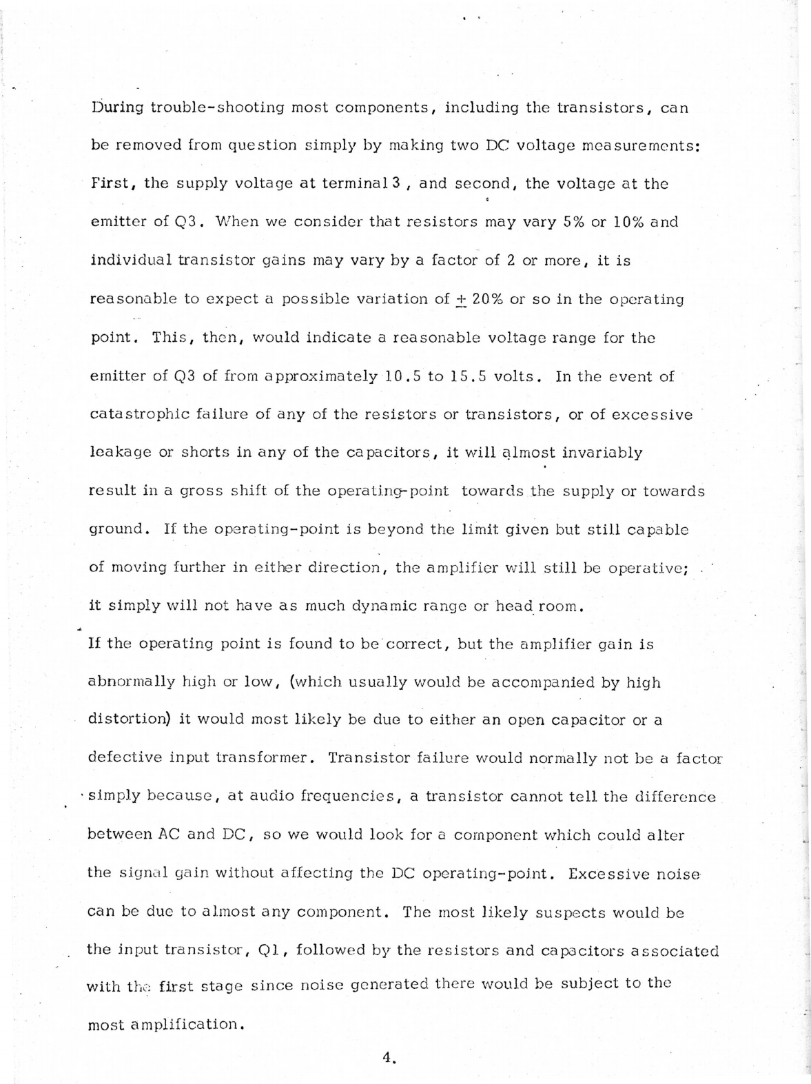
During
trouble-shooting
most
components,
including
the
transistors,
can
be
removed
from
question
simply
by
making
two
DC
voltage
measurements:
First,
the
supply
voltage
at
terminal
3
,
and
second,
the
voltage
at
the
a
emitter
of
Q3.
When
we
consider
that
resistors
may
vary
5%
or
10%
and
individual
transistor
gains
may
vary
by
a
factor
of
2
or
more,
it
is
reasonable
to
expect
a
possible
variation
of
+
20%
or
so
in
the
operating
point.
This,
then,
would
indicate
a
reasonable
voltage
range
for
the
emitter
of
Q3
of
from
approximately
10.5
to
15.5
volts.
In
the
event
of
catastrophic
failure
of
any
of
the
resistors
or
transistors,
or
of
excessive
leakage
or
shorts
in
any
of
the
capacitors,
it
will
almost
invariably
result
in
a
gross
shift
of
the
operating-point
towards
the
supply
or
towards
ground.
If
the
operating-point
is
beyond
the
limit
given
but
still
capable
of
moving
further
in
either
direction,
the
amplifier
will
still
be
operative;
.
it
simply
will
not
have
as
much
dynamic
range
or
head
room.
If
the
operating
point
is
found
to
be
correct,
but
the
amplifier
gain
is
abnormally
high
or
low,
(which
usually
would
be
accompanied
by
high
distortion)
it
would
most
likely
be
due
to
either
an
open
capacitor
or
a
defective
input
transformer.
Transistor
failure
would normally
not
be
a
factor
simply
because,
at
audio
frequencies,
a
transistor
cannot
tell
the
difference
between
AC
and
DC,
so
we
would
look
for
a
component
which
could
alter
the
signal
gain
without
affecting
the
DC
operating-point.
Excessive
noise
can
be
due
to
almost
any
component.
The
most
likely
suspects
would
be
the
input
transistor,
Ql,
followed by
the
resistors
and
capacitors
associated
with
the
first
stage
since
noise
generated
there
would
be
subject
to
the
most
amplification.
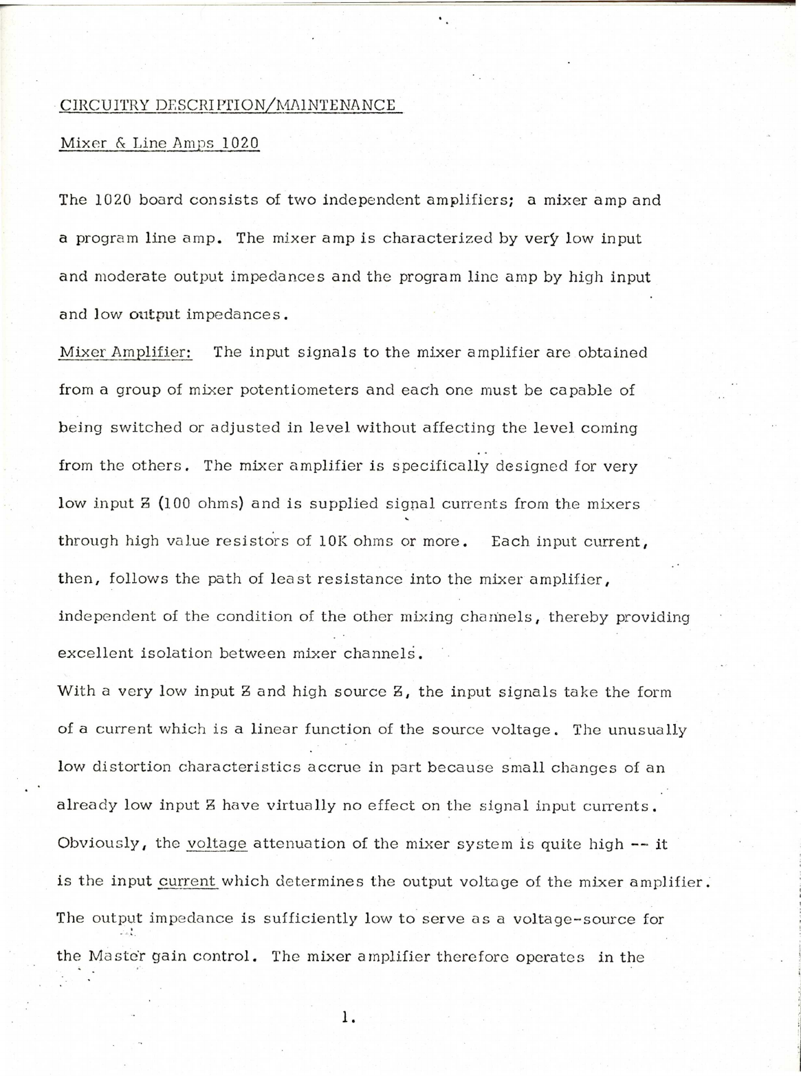
CIRCUITRY
DESCRIPTION/MAINTENANCE
Mixer
&
Line
Amps
1020
The
1020
board
consists
of
two
independent
amplifiers;
a
mixer
amp
and
a
program
line
amp.
The
mixer
amp
is
characterized
by
very
low
input
and
moderate
output
impedances
and
the
program
line
amp
by
high
input
and
low
output
impedances.
Mixer
Amplifier:
The
input
signals
to
the
mixer
amplifier
are
obtained
from
a
group
of
mixer
potentiometers
and
each
one
must
be
capable
of
being
switched
or
adjusted
in
level
without
affecting
the
level
coming
from
the
others.
The
mixer
amplifier
is
specifically
designed
for
very
low
input
3
(100
ohms)
and
is
supplied
signal
currents
from
the
mixers
through
high
value
resistors
of
10K
ohms
or
more.
Each
input
current,
then,
follows
the
path
of
least
resistance
into
the
mixer
amplifier,
independent
of
the
condition
of
the
other
mixing
channels,
thereby
providing
excellent
isolation
between
mixer
channels.
With
a
very
low
input
Z
and
high
source
Z,
the
input
signals
take
the
form
of
a
current
which
is
a
linear
function
of
the
source
voltage.
The
unusually
low
distortion
characteristics
accrue
in
part
because
small
changes
of
an
already
low
input
Zhave
virtually
no
effect
on
the
signal
input
currents.
Obviously,
the
voltage
attenuation
of
the
mixer
system
is
quite
high
—
it
is
the
input
current
which
determines
the
output
voltage
of
the
mixer
amplifier.
The
output impedance
is
sufficiently
low
to
serve
as
a
voltage-source
for
the
Master
gain
control.
The
mixer
amplifier
therefore
operates
in
the
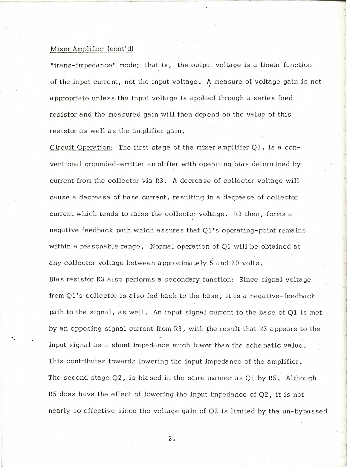
Mixer
Amplifier
(cont'd)
"trans-impedance"
mode;
that
is,
the
output
voltage
is
a
linear
function
of
the
input
current,
not
the
input
voltage.
A
measure
of
voltage gain
is
not
appropriate
unless
the
input
voltage
is
applied
through
a
series
feed
resistor
and
the
measured
gain
will
then
depend
on
the
value
of
this
resistor
as
well
as
the
amplifier
gain.
Circuit
Operation:
The
first
stage
of
the
mixer
amplifier
Ql,
is
a
con-
ventional
grounded-emitter
amplifier
with
operating
bias
determined
by
current
from
the
collector
via
R3.
A
decrease
of
collector
voltage
will
cause
a
decrease
of
base
current,
resulting
in
a
decrease
of
collector
current
which
tends
to
raise
the
collector
voltage.
R3
then,
forms
a
negative
feedback
path
which
assures
that
Ql's
operating-point
remains
within
a
reasonable
range.
Normal
operation
of
Ql
will
be
obtained
at
any
collector
voltage
between
approximately
5
and.
20
volts.
Bias
resistor
R3
also
performs
a
secondary
function:
Since
signal
voltage
from
Ql's
collector
is
also
fed
back
to
the
base,
it
is
a
negative-feedback
path
to
the
signal,
as
well.
An
input
signal
current
to
the
base
of
Ql
is
met
by
an
opposing
signal
current
from
R3,
with
the
result
that
R3
appears
to
the
input
signal
as
a
shunt
impedance
much
lower
than
the
schematic
value.
This
contributes
towards
lowering
the
input
impedance
of
the
amplifier.
The
second
stage
Q2,
is
biased
in
the
same
manner
as
Ql
by
R5.
Although
R5
does
have
the
effect
of
lowering
the
input
impedance
of
Q2,
it
is
not
nearly
so
effective
since
the
voltage
gain
of
Q2
is
limited
by
the
un-bypassed
2.

Circuit
Operation:
(cont'd)
emitter
resistor
R8;
therefore,
the
relative
feedback
signal
current
is
much
lower.
The
voltage
gain
of
Q2
is
determined
by
the
ratio
of
resistor
R8
to
the
collector
load
impedance
R7.
Consider
Q2
as
having
a
typical
beta
of
100,
and
no
external
load
on
the
collector.
The
emitter
resistor
R8
carries
the
collector
current
plus
the
base
current,
but
since
the
base
current
is
only
1%
of
the
collector
current,
we
can
assume
the
emitter
and
base
currents
to
be
the
same
for
all
practical
purposes.
The
emitter
is
not
bypassed,
so
a
change
of
voltage
at
the
base
results
in
an
equal
change
at
the
emitter.
This
in
turn
changes
both
emitter
and
collector
currents
by
the
same
amount.
But
the
collector
current
is
flowing
through
a
resistor,
R7, which
is
ten
times
larger
than
R8,
so
it
must
cause
ten
times
the
voltage-change.
The
voltage-gain
of
Q2,
then,
must
simply
be
the ratio
of
R7
to
R8,
or
ten.
In
normal
application,
Q2
is
loaded
by
the
Master
gain
control
(5K
ohms)
so
the
AC
collector
load
impedance
is
1.75
K
ohm
instead
of
2.7K
resulting
in
a
normal
stage
gain
of
approximately
6.5,or
16db.
The
unbypassed
R8,
then,
forms
a
third
negative-feedback
path
—
this
time
to
fix
the
ac
gain
—
because
the
collector
current
through
R8
produces
an
emitter
voltage
change
which
tends
to
cancel
the
input
base
voltage,
thereby
limiting
the
gain.
The
collector
voltage
of
Q2,
like
Ql,
is
not
critical.
The
nominal
signal
level
at
the
collector
of
Q2
is
0dbm,
or
about
1
volt
rms.
If
we
allow
for
12db
of
headroom,
or
4volts
rms,
the
collector
must
be
free
to
swing
12
volts
peak-to-peak
or
6
volts
in
either
direction.
So
an
operating-
point
between
approximately
8
and
18
volts
will
assure
normal
operation.
3.
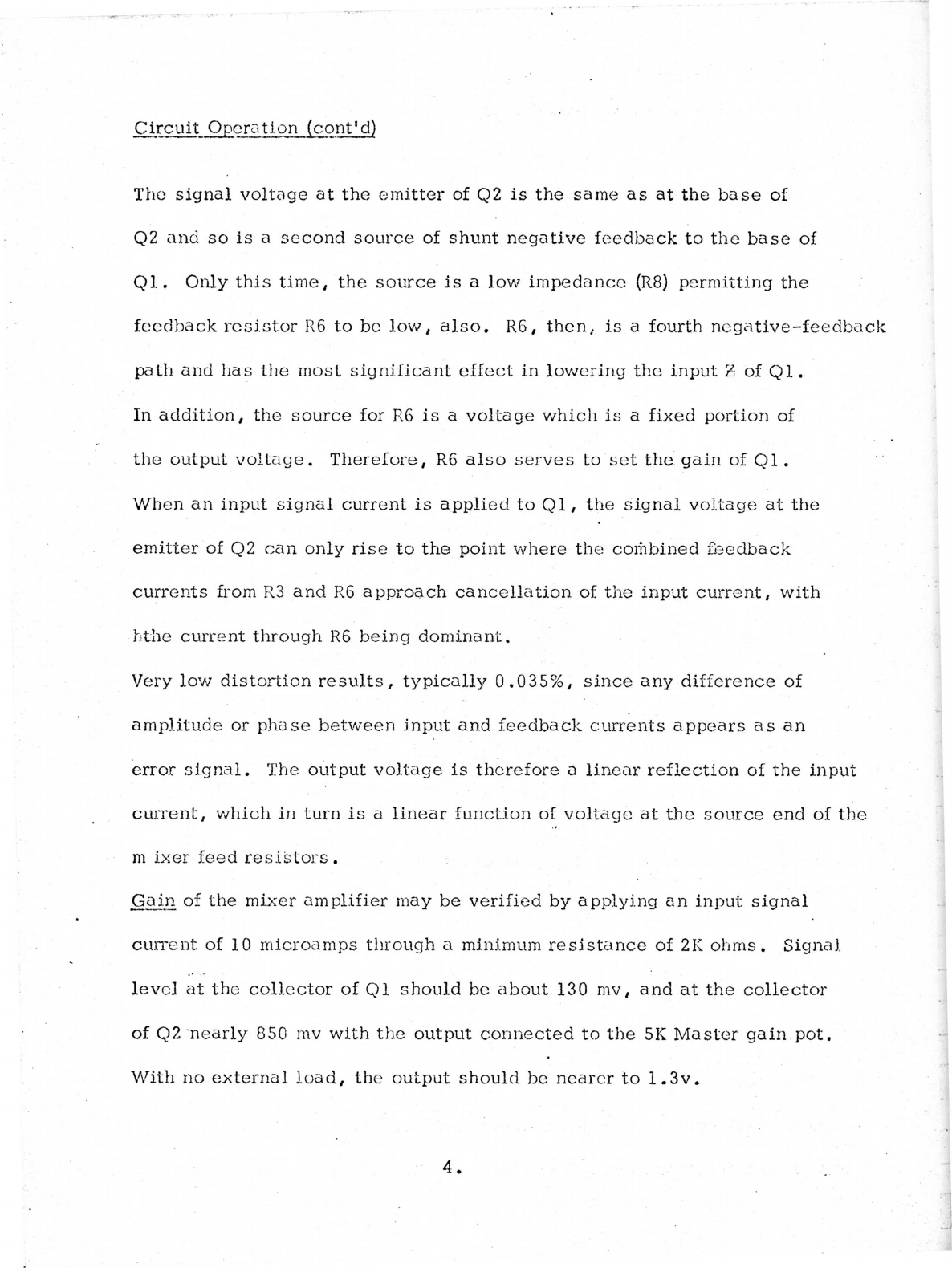
Circuit
Operation
(cont'd)
The
signal
voltage
at
the
emitter
of
Q2
is
the
same
as
at
the
base
of
Q2
and
so
is
a
second
source
of
shunt
negative
feedback
to
the
base
of
Ql.
Only
this
time,
the
source
is
a
low
impedance
(R8)
permitting
the
feedback
resistor
R6
to
be
low,
also.
R6,
then,
is
a
fourth
negative-feedback
path
and
has
the
most
significant
effect
in
lowering
the
input
2
of
Ql.
In
addition,
the
source
for
R6
is
a
voltage
which
is
a
fixed
portion
of
the
output
voltage.
Therefore,
R6
also
serves
to
set
the
gain
of
Ql.
When
an
input
signal
current
is
applied
to
Ql,
the
signal
voltage
at
the
emitter
of
Q2
can
only
rise
to
the
point
where
the
combined
feedback
currents
from
R3
and
R6
approach
cancellation
of
the
input
current,
with
hthe
current
through
R6
being
dominant.
Very
low
distortion
results,
typically
0.035%,
since
any
difference
of
amplitude
or
phase
between
input
and
feedback
currents
appears
as
an
error
signal.
The
output
voltage
is
therefore
a
linear
reflection
of
the
input
current,
which
in
turn
is
a
linear
function
of
voltage
at
the
source
end
of
the
m
ixer
feed
resistors.
Gain
of
the
mixer
amplifier
may
be
verified
by
applying
an
input
signal
current
of
10
microamps
through
a
minimum
resistance
of
2K
ohms.
Signal
level
at
the
collector
of
Ql
should
be
about
130
mv,
and
at
the
collector
of
Q2
nearly
850
mv
with
the
output
connected
to
the
5K
Master
gain
pot.
With
no
external
load,
the
output
should
be
nearer
to
1.3v.
Circuit
Operation
(cont'd)
Do
not
be
concerned
by
10
or
20%
gain
variations,
since
many
10%
resistors
are
used
and
are
easily
compensated
for
by
the
normal
control
settings.
Line Amplifier:
.
The
input
stage,
Q3
and
04,
is
a
differential
comparator
which
performs
three
separate
functions:
First
is
signal
amplification
wherein
Q3
operates
in
the
transconductance
mode;
that
is,
the
collector
current
is
a
function
of
base
voltage.
Second,
a
large
proportion
of
the
average
dc
voltage
at
the
emitters
of
Q6
and
Q7,
which
appears
at
the
base
of
Q4,
is
compared
to
the
base
voltage
of
Q3
to
stabilize
the
operating-points
of
the
output
transistors.
And
third,
a
small
proportion
of
the
output
signal,
which
is
fed
back
to
the
base
of
Q4,
is
compared
to
the
input
signal
at
the
base
of
Q3,
thereby
setting
the
ac
gain.
When
power
is
first
applied,
C13
must
be
charged
to
one-half
of
the
supply
voltage
through
Q6,
and
to
protect
Q6
the
charging-rate
must
be
limited.
QG
cannot
turn
on
until
Q5
and
hence
Q3
begin
to
conduct.
But
Q3
cannot
conduct
any
faster
than
C6
can
charge,
so
C6
not
only
filters
the
bias
current
to
03,
but
also
controls
the
charge-rate
of
C13.
The
ideal
dc
operating-point
for
the
output
transistors
Q6
and
Q7
is
one
half
of
the
supply
voltage,
because
this
is
the
point
at
which
the
greatest
peak-
to-peak
output-voltage
swing,
or
headroom,
is
available.
When
first
turned
on,
C6
charges
and
the
base
of
Q3
is
brought
to
40%
of
the
supply
voltage.
As
C13
charges,
the
voltage
common
to
the
emitters
of
Q6
and
Q7
rises
towards
the
supply.
Upon
reaching
one-half
of
the
supply
voltage,
80%
of
this
(or
40%
of
the
supply
voltage)
reaches
the
base
of
Q4
via
dc
divider
R16,
R15,
5.
Table of contents
Other Sparta Recording Equipment manuals


