Installation Guide
Vision2MPEG Solution
Overview
The Vision2MPEG Solution (FG3100-20K) provide multiple live MPEG channels
over a standard IP network for up to 20 users. The Vision2Producer channels
allow scheduling for timed live channel playback of pre-recorded video content via
multicast on Intranets. The following table lists the hardware and tools included in
each MPEG solution:
The Vision2Master server controls the core management application.
The following table lists the specifications for the Master Server:
Installation
The following steps show you how to setup a typical configuration for the MPEG
Solution.
1. Connect the power supply to the rear of the Vision2Master server.
2. Connect an RJ-45 LAN cable to LAN port one on the back of the Vision2
Master server. Connect the other end of the cable to a Gigabit port on a
layer 3 network switch.
Note: To prevent multicast traffic from flooding your network, use LAN port 2 as
the Vision2 client side multicast interface.
Note: Vision2uses typical Cat5/5e/6 cabling for RJ-45 connections.
3. Connect an RJ-45 LAN cable to the LAN port on the rear of the MAX-CSE
encoder. Connect the other end of the cables to any of the ports on your
LAN switch.
4. Connect a composite or S-video cable to the corresponding ports on the rear
of the MAX-CSE encoder. Connect the other end of the cables to a device
capable of producing a video signal. The MAX-CSE encodes the video
signals into MPEG-2 multicast streams.
5. Repeat steps 3 and 4 for each additional MAX-CSE encoder you have in
your Vision2solution.
Starting and Accessing Vision2
Perform these steps to start and access Vision2:
1. Power on the Vision2server. It may take a few minutes to boot.
2. Test that you can access the server via the LAN. You can run this test by
accessing a Command Prompt using the Ping command. For example:
ping v2AMX-SVCTAG
If the server responds, continue to step 3.
3. Using a web browser on a PC with network access, navigate to
http://<servername>/admin.aspx. The V2ServicesManager appears.
Adding and Activating Services
After opening and accessing Vision2, you must activate the available services for
it with an appropriate license key.
1. Click Manage <name of server> in the services list on the left side of the
page to display the available services for the server.
2. Enter a valid license code in the New Service License Code field.
3. Click Check License Code. If the code is valid, the License Changes area
displays the number of licenses available for each type of service.
4. Click Apply updated License to apply the license code and create the
requested services. The new services populate the Current Status of
Services list at the top of the page.
5. Select an inactive service from the Current Status of Services list. Inactive
services appear highlighted in green in the list and have a value of False in
the Activated column.
6. Click Activate Service so you can manage the service.
Repeat steps 5 and 6 to activate any remaining inactive services.
Vision2MPEG Solution Specifications
V2-2100-MPEG
V2 Live MPEG 2
Channels and 1
Producer
(FG3100-20K):
• 2 Live MPEG2 Channels (20 Users)
• 1 Producer Channel
•1Vision
2Master Server
• 2 MAX-CSE Encoders
• 250 Archive Hours
FIG. 1 Vision2Master server
Vision2Master Server Specifications
Processor: 1 Intel® E5500 Xeon® 5500 series processor
Memory: 4GB 1066MHz (2x2GB) UDIMMs
Storage: • 2 146GB 15K RPM serial-attach SCSI 3Gbps 3.5-in HotPlug
hard drives
• 4 750GB 7.2K RPM Near Line SAS 3.5-in HotPlug hard drives
Power: 570W, 90-264VAC, 47-63Hz
Front Panel Components:
USB ports 2 USB 2.0 ports for mouse, keyboard, or external peripheral
devices
Video
connector 1 15-pin (female) video connector for connecting a video output
device such as a PC monitor
LCD panel Displays system ID, status info, and error messages.
Power button Press to power on server.
Rear Panel Components:
Video
connector 1 15-pin (female) video connector for connecting a video output
device such as a PC monitor
Serial
connector 1 9-pin (male) serial connector
USB port 2 USB 2.0 ports for mouse, keyboard, or external peripheral
devices
LAN
connectors 4 RJ-45 LAN ports for connecting to a network router (10/100/
1000 Ethernet)
Rack Mount Sliding Ready™ rails with Cable Management arm
Operating
Environment: Operating Temperature: 10º C to 35º C (50º F to 95º F)
Storage Temperature: -40º C to 65º C (-40º F to 149º F)
Operating Relative Humidity (non-condensing twmax=29º C):
20% to 80% non-condensing
Maximum Humidity Gradient: 10% per hour, operational and
non-operational conditions
Storage Relative Humidity: 5% to 95% non-condensing
(twmax=38º C)
Dimensions
(HWD): 3.4" (8.64cm) H x 17.44" (44.31cm) W x 26.8" (68.07cm) D
Weight: Rack Weight 57.54 lbs (26.1 kg)
Included
Accessories: 1 PSN6.5, Power Supply (FG423-41)
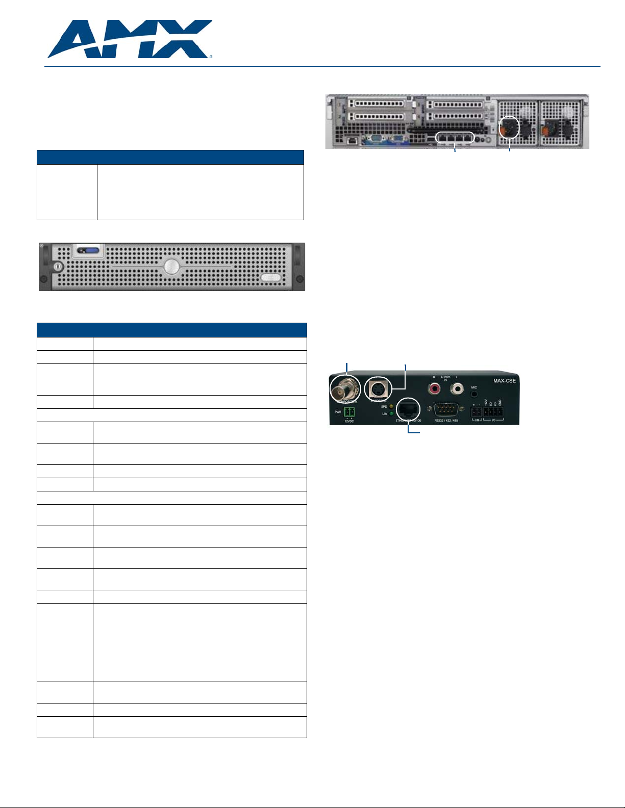
FIG. 2 Vision2Master server (rear-view)
FIG. 3 MAX-CSE Encoder (rear-view)
LAN port
S-Video port
Composite port


