SPARTAN sport BR-2444 User manual

BR-2444
ROWING MACHINE

Important Safety Information
Please keep this manual in a safe place for reference.
1. It is important to read this entire manual before assembling and using the equipment. Safe
and efficient use can only be achieved if the equipment is assembled, maintained and used
properly. It is your responsibility to ensure that all users of the equipment are informed of all
warnings and precautions.
2.
Before starting any exercise program you should consult your doctor to determine
if you have
any physical or health conditions that could create a risk to your health and safety, or prevent
you from using the equipment properly. Your doctor's advice is essential if you are taking
medication that affects your heart rate, blood pressure or cholesterol level.
3. Be aware of your body's signals. Incorrect or excessive exercise can damage your health.
Stop exercising if you experience any of the following symptoms: Pain, tightness in
your chest, irregular heartbeat, extreme shortness of breath, feeling light headed,
dizzy or nauseous. If you do experience any of these conditions you should consult
your doctor before continuing with your exercise program.
4. Keep children and pets away from the equipment. The equipment is designed for adult use
only.
5. Use the equipment on a solid, flat level surface with a protective cover for your floor or carpet.
For safety, the equipment should have at least 0.5 metre of free space all around it.
6. Before using the equipment, check the nuts and bolts are securely tightened.
7. The safety level of the equipment can only be maintained if it is regularly examined for
damage and/or wear and tear.
8. Always use the equipment as indicated. If you find any defective components whilst
assembling or checking the equipment, or if you hear any unusual noise coming from the
equipment during use, stop. Do not use the equipment until the problem has been rectified.
9. Wear suitable clothing whilst using the equipment. Avoid wearing loose clothing
which may
get caught in the equipment or that may restrict or prevent movement.
10. The equipment has been tested and certified to EN957 under class H.C. Suitable for domestic,
home use only. Maximum weight of user: 100kg. Braking is speed independent.
11. The equipment is not suitable for therapeutic use.
12. Care must be taken when lifting or moving the equipment so as not to injure your back. Always
use proper lifting techniques and/or use assistance.
E
El
lo
od
de
ed
d-
-V
Vi
ie
ew
w
A
As
ss
se
em
mb
bl
ly
y
D
Dr
ra
aw
wi
in
ng
g
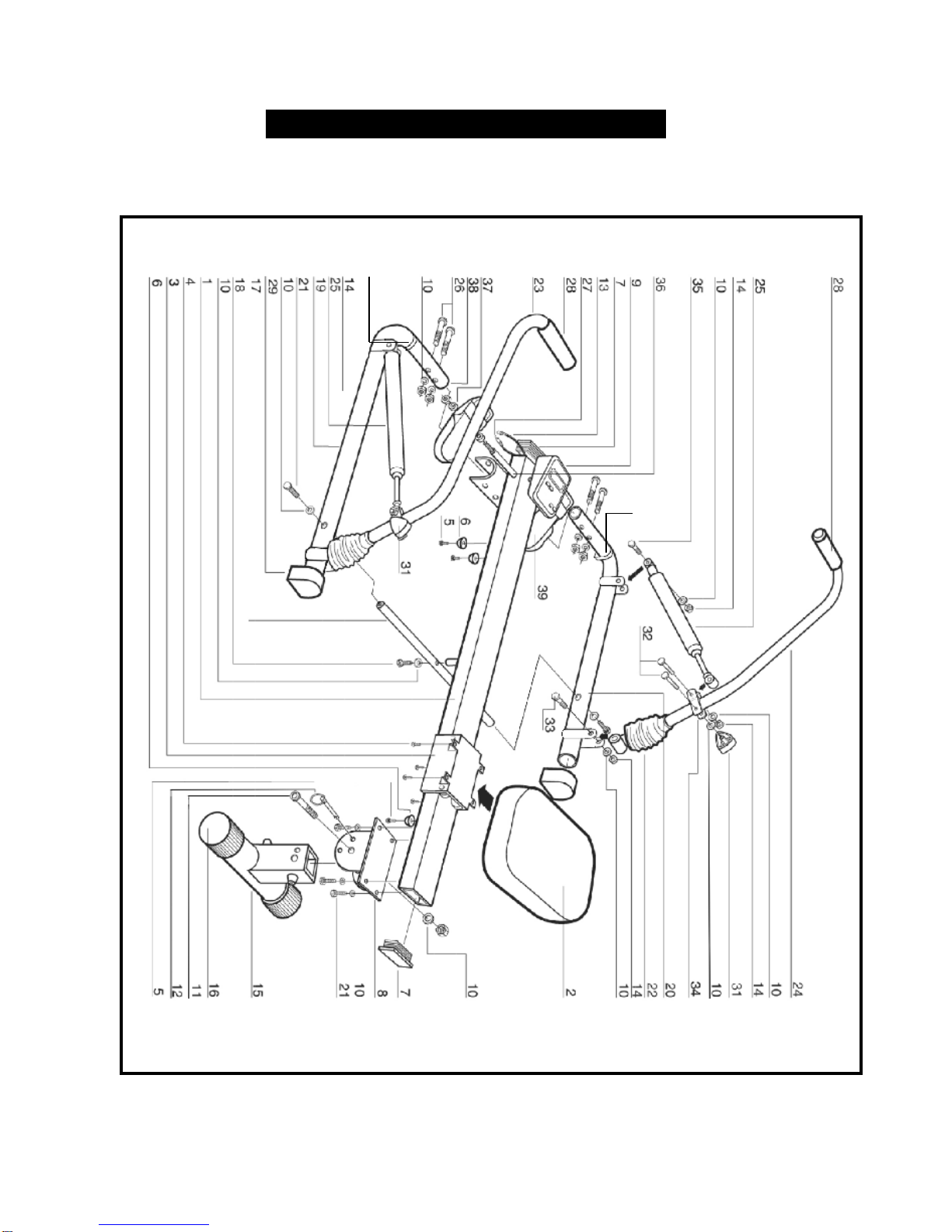
30
30

PART NO.
DESCRIPTION Q'TY
1 Main Frame Tube 1
2 Seat 1
3 Seat Carriage 1
4
Slot Head Screw (1/4"x1/2")
4
5
Self Tapping Screw (M4x16)
3
6 End Stop 3
7 Plastic Cap 2
8 Rear Stabilizer Bracket 1
9 Computer 1
10 Washer 19
11 Key Head Bolt (M8x70L) 1
12 Fixing Pin 1
13 Upper Sensor Wire 1
14 Nut (M8) 8
15 Rear Stabilizer 1
16 End Cap (Rear) 2
17 Link Bar 1
18 Hex Head Bolt (M8x30) 1
19 Left Frame Tube 1
20 Right Frame Tube 1
21 Hex Head Bolt (M8x15L) 6
22 Rubber Sleeve 2
23 Left Hand Rower Arm 1
24 Right Hand Rower Arm 1
25 Hydraulic Cylinder 2
26 Carriage Bolt (M8x50L) 4
27 Lower Sensor Wire 1
28 Foam Grips 2
29 Rear Rubber Feet 2
30 Front Rubber Feet 2
31 Locking Knob 2
32 Carriage Bolt (M8x40L) 4
33 Hex Head Bolt (M8x50) 2
34 "H" Bracket 2
35 Hex Head Bolt (M8x40) 2
36 Pedal Spindle Bar 1
37 Rubber Washer 4
38 Large Nut (1/2") 2
39 Pedal 2
PARTS LIST

A
As
ss
se
em
mb
bl
ly
y
I
In
ns
st
tr
ru
uc
ct
ti
io
on
n
STEP 1
Make sure the sensor wire plug
is accessible from the front of
the main frame tube.
STEP 3
Attach the rear stabilizer (pt.15)
to the main frame tube (pt.1)
using 4 hex head bolt (pt.21)
and 4 washers (pt.10).
STEP 2
Attach the seat to the carriage
using 4 slot head screws (pt.4).
Note: The thicker end of the seat
should be facing the rear end of
the rower.
Table of contents


