SPARTAN sport 1271 User manual

ITEM NO.: 1271
OWNER’S
MANUAL
IMPORTANT: Read all instructions carefully before using this product. Retain this

1
owner’s manual for future reference.
The specifications of this product may vary from this photo and are subject to change without
prior notice.
TABLE OF CONTENTS
IMPORTANT SAFETY INSTRUCTIONS ------------------------------------------- 2
EXPLODED VIEW ----------------------------------------------------------------------- 3
PARTS LIST ------------------------------------------------------------------------------- 4
HARDWARE LIST ----------------------------------------------------------------------- 5
TOOLS -------------------------------------------------------------------------------------- 5
ASSEMBLY INSTRUCTIONS --------------------------------------------------------- 6
OPERATING THE COMPUTER ------------------------------------------------------ 10
STORAGE --------------------------------------------------------------------------------- 12
MOVING THE TREADMILL ------------------------------------------------------------ 13
ADJUSTMENTS -------------------------------------------------------------------------- 14
MAINTENANCE -------------------------------------------------------------------------- 17
TROUBLESHOOTING ------------------------------------------------------------------ 17
WARM UP AND COOL DOWN ROUTINE ----------------------------------------- 18

2
IMPORTANT SAFETY INSTRUCTIONS
Basic precautions should always be followed, including the following safety
instructions when using this magnetic treadmill. Read all instructions before using
this magnetic treadmill.
1. Check every part of the equipment before exercise. If there is any defective
component, replace it immediately; keep the equipment out of use until repair.
2. Make sure all parts, bolts and nuts are well assembled and locked before exercise.
3. Never insert any object into any opening.
4. Never operate this magnetic treadmill if it is not working properly. If it has been
dropped or damaged, or been exposed to water, return the appliance to a service
center
for examination and repair.
5. Do not attempt any maintenance or adjustments other than those described in this
manual. Should any problems arise, discontinue use and consult your local dealer.
6. Wear comfortable and suitable clothing when using the magnetic treadmill. Do not
use
the magnetic treadmill barefoot, in only socks or in sandals, always wear athletic
shoes.
7. Never wear loose clothing because it could run the risk of getting caught in the
magnetic
treadmill.
8. Keep children and pets away from the equipment while in use.
9. Do not use the magnetic treadmill outdoors. This magnetic treadmill is for household
use only.
10. Only one person should be on the magnetic treadmill while in use.
11. Keep the magnetic treadmill on a solid, level surface with the minimum safety area
clearance of 2000mm x 1000mm around the unit. Be sure the area around the
magnetic treadmill remains clear during use and has adequate clearance.
12. Hold the handlebar with your hands when starting or stopping exercise and increasing
or decreasing the speed.
13. If feeling chest pains, nausea, dizziness, or shortness of breath, you should stop
exercising immediately and consult your physician before continuing.
14. The maximum weight capacity for this product is 110 kg.
WARNING: Before beginning any exercise program consult your
physician. This is especially important for the people who are over 35 years old or
who have pre-existing health problems. Read all instructions before using any
fitness equipment.
3
CAUTION: Read all instructions carefully before operating this product.
Retain this Owner’s Manual for future reference.
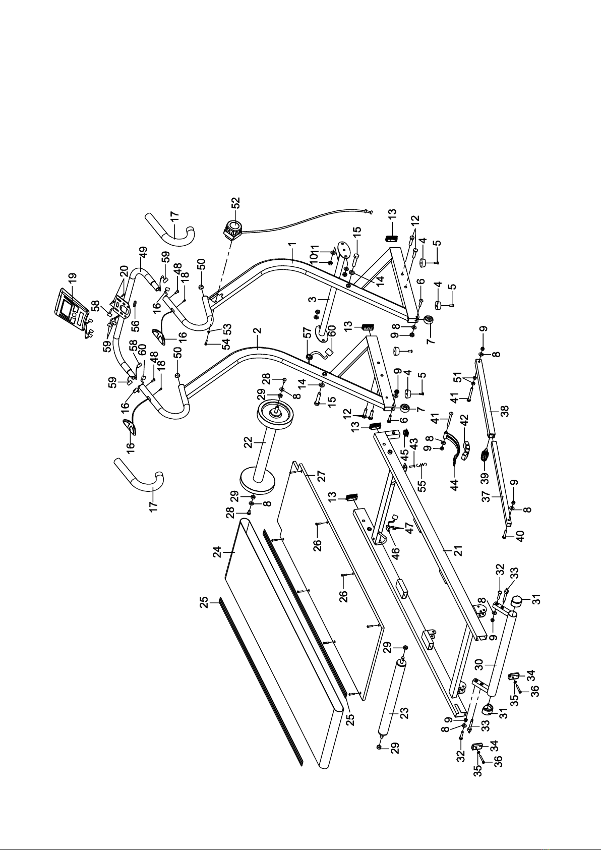
EXPLODED VIEW

4
PARTS LIST
No.
Description
Qty
No.
Description
Qty
001
Right Handlebar Support Frame
513x40x1180
1
031
Incline Adjustment Frame End Cap
Ø25x27
2
002
Left Handlebar Support Frame
513x40x1180
1
032
Bolt M8x38
2
003
Connection Support Frame
103x535x54
1
033
Locking Pin
2
004
Rubber Pad Ø33xØ38x16
4
034
Rear Roller Adjustment Bolt Plate
2
005
Bolt M6x16
4
035
Washer Ø6
2
006
Bolt M8x35
2
036
Rear Roller Adjustment Bolt M6x55
2
007
Wheel Ø50xØ8x20
2
037
Safety Tube A
1
008
Washer Ø8
9
038
Safety Tube B
1
009
Nylon Nut M8
7
039
Spring Knob
1
010
Nylon Nut M10
4
040
Bolt M8x42
1
011
Washer Ø10
4
041
Bolt M8x75
2
012
Bolt M10x40
4
042
Magnet
4
013
End Cap (25x50)
4
043
Hex Head Bolt M5x25
1
014
Washer Ø12
2
044
Magnet Bracket
1
015
Bolt M12x65
2
045
Square End Cap (25x25)
1
016
Hand Pulse Sensor with Wire
2
046
Sensor with Wire 100mm
1
017
Foam Grip Ø28xØ23x280
2
047
Screw ST2.9x9.5
2
018
Screw M4x15mm.
2
048
Bolt M6x12
2
019
Computer XLG-605
1
049
Handlebar
1
020
Bolt M5x10
2
050
Handlebar End Cap Ø25
2
021
Main Frame
1
051
Nut M8
2
022
Front Roller Ø160xØ42x445
1
052
Tension Control Knob L=1080mm
1
023
Rear Roller Ø42x443
1
053
Curve Washer for Tension Control
Knob Ø5
1
024
Running Belt 360x2532x1.3
1
054
Bolt for Tension Control Knob
M5x25
1
025
Side Rail 30x1056x2
2
055
Spring
1
026
Bolt M5x25
8
056
Wire Plug Ø25xØ13x4
1
027
Running Deck 1114x458x12
1
057
Wire Plug Ø12
1

5
HARDWARE LIST
TOOLS
028
Bolt M8x15
2
058
Sensor Cable I (L=450mm)
1
029
Front Roller Sleeve
4
059
Sensor Cable II (L=450mm)
2
030
Incline Adjustment Frame
511x24x124
1
060
Sensor Cable III (L=1000mm)
1
Allen Wrench #5
1 PC
Multi Hex Tool S13, S17, S19
2 PCS
Multi Hex Tool with Phillips Screwdriver
1 PC
(10) Nylon Nut M10
4 PCS
(11) Washer Ø10
4 PCS
(12) Bolt M10x40
4 PCS
(14) Washer Ø12
2 PCS
(15) Bolt M12x65
2 PCS
(48) Bolt
M6x12
2 PCS
6
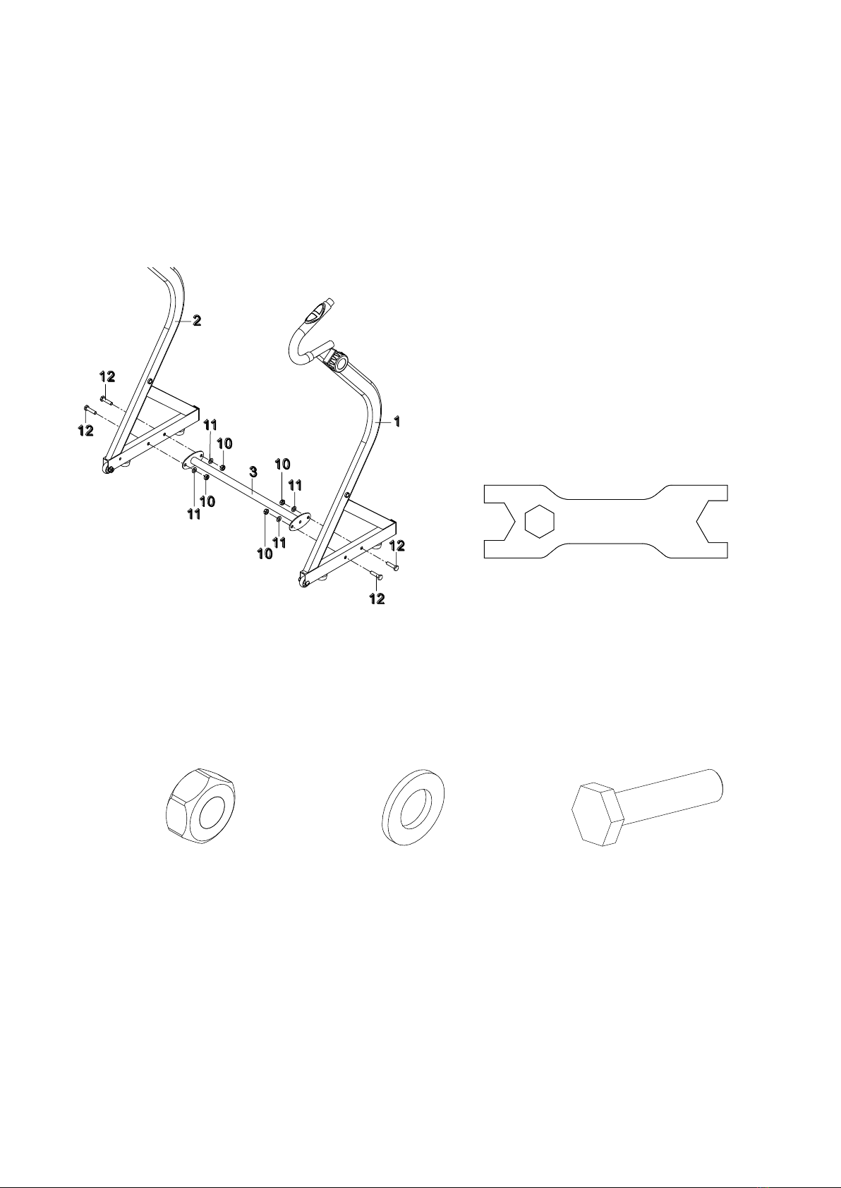
ASSEMBLY INSTRUCTIONS
Step 1
Attach the Connection Support Frame (3) onto the Right/Left Handlebar Support Frames
(1, 2) with four M10 Nylon Nuts (10), four Ø10 Washers (11), and four M10x40 Bolts (12).
Tighten bolts with two Multi Hex Tools provided.
Hardware:
2 Multi Hex Tools (S13, S17, S19)
Tool:
(10) Nylon Nut M10
4 PCS
(11) Washer Ø10
4 PCS
(12) Bolt M10x40
4 PCS
7
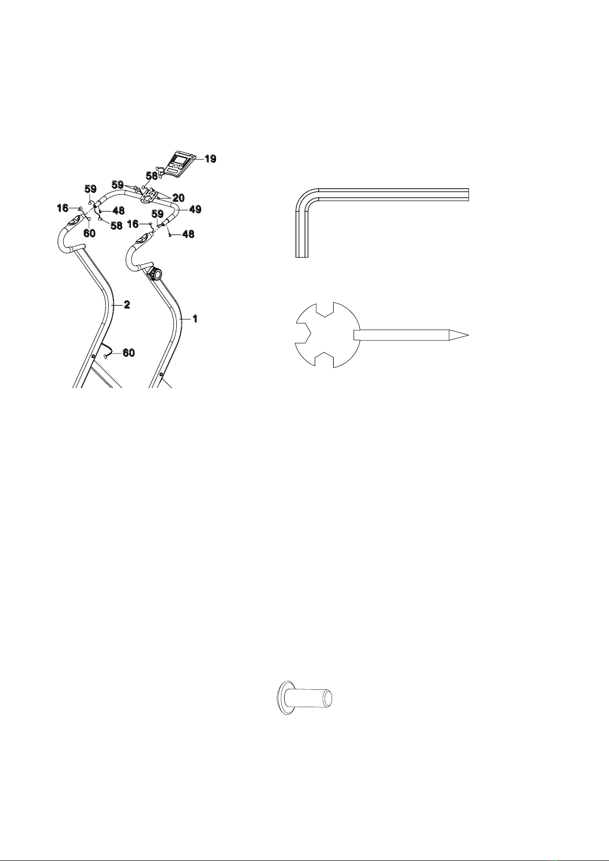
Step 2
Connect the Hand Pulse Sensor Wire (16) from the Right Handlebar Support Frame (1) to
the Sensor Cable II (59) from the Handlebar (49).
Connect the Hand Pulse Sensor Wire (16) and Sensor Cable III (60) from the Left
Handlebar Support Frame (2) to the Sensor Cable II (59) and Sensor Cable I (58) from the
Handlebar (49).
Attach the Handlebar (49) into the Right/Left Handlebar Support Frames (1, 2) with two
M6x12 Bolts (48). Tighten bolts with the Allen Wrench provided.
Remove two M5x10 Bolts (20) from the Computer (19). Remove bolts with the Multi Hex
Tool with Phillips Screwdriver provided.
Connect the Sensor Cable I (58) and Sensor Cables II (59) from the Handlebar (49) to the
wires that come from the Computer (19).
Attach the Computer (19) onto the plate of the Handlebar (49) with two M5x10 Bolts (20)
that
were removed. Tighten bolts with the Multi Hex Tool with Phillips Screwdriver provided.
Hardware:
Allen Wrench #5
Multi Hex Tool with Phillips Screwdriver
Tool:
(48) Bolt
M6x12
2 PCS

8
Step 3
Attach the Main Frame (21) onto the Right/Left Handlebar Support Frames (1, 2) with two
Ø12 Washers (14) and two M12x65 Bolts (15). Tighten bolts with two Multi Hex Tools
provided.
Connect the Sensor Wire (46) from the Main Frame (21) to the Sensor Cable III (60) from
the Left Handlebar Support Frame (2).
NOTE: It is recommended that you always use the aid of a second person when
assembling the treadmill.
Hardware:
2 Multi Hex Tools (S13, S17, S19)
Tool:
(14) Washer Ø12
2 PCS
(15) Bolt M12x65
2 PCS

9
Step 4
Remove one Ø8 Washer (8), one M8 Nylon Nut (9), one M8x75 Bolt (41), and two M8 Nuts
(51) from the Safety Tube B (38). Remove bolt and nylon nut with the Allen Wrench and
Multi Hex Tool with Phillips Screwdriver provided.
Remove one Ø8 Washer (8), one M8 Nylon Nut (9), and one M8x42 Bolt (40) from the
Safety Tube A (37). Remove bolt and nylon nut with the Allen Wrench and Multi Hex Tool
with Phillips Screwdriver provided.
Attach the Safety Tube B (38) onto the Left Handlebar Support Frame (2) with one Ø8
Washer (8), one M8 Nylon Nut (9), one M8x75 Bolt (41), and two M8 Nuts (51) that were
removed. Tighten bolt and nylon nut with the Allen Wrench and Multi Hex Tool with
Phillips Screwdriver provided.
Attach the Safety Tube A (37) onto the Main Frame (21) with one Ø8 Washer (8), one M8
Nylon Nut (9), and one M8x42 Bolt (40) that were removed. Tighten bolt and nylon nut
with
the Allen Wrench and Multi Hex Tool with Phillips Screwdriver provided.
Allen Wrench #5
Multi Hex Tool with Phillips Screwdriver
Tool:

10
OPERATING THE COMPUTER
USING YOUR COMPUTER
The computer can be activated by pressing the any key on the
computer or by running. If you leave the equipment idle for 4-5
minutes, the power will turn off automatically.
KEY FUNCTIONS:
MODE: Press the MODE key to select each function of computer.
Press and hold the MODE key for 3 seconds to reset all data values to zero except the
TOTAL (ODOMETER) data values.
SET: Press the SET key to set data values of TMR (TIMER), DST (DISTANCE), or
CAL (CALORIES) for target pre-setting.
RESET: Press the RESET key to reset the data values of TIME, DISTANCE, or CALORIES
to zero for target presetting.
RESET: Press the RESET key to reset data values of TMR (TIMER), DST (DISTANCE), or
CAL (CALORIES) to zero.
COMPUTER FUNTIONS:
SCAN: Press the MODE key until the screen displays SCAN, the computer will
automatically
scan the function of TMR, SPD, DST, TOTAL, and CAL every 4 seconds.
TMR (TIMER): Displays your elapsed workout time in minutes and seconds. You may also
pre-set target time in STOP mode before training. To set TIMER press the MODE key until
the screen displays TMR. Press the SET key to change the time, each time you press the
SET key time should change by 1 minute. Press the RESET key to clear the target time to
zero. The pre-set target time range is from 0:00 to 99:00 minutes. Once you pre-set
target time and then start to exercise, time starts counting down from pre-set target time to
0:00 per 1 second backward. When the pre-set target time counts down to 0:00, time will
start to count up immediately and the computer will begin beeping to remind you.
SPD (SPEED): Displays the current training speed.

11
DST (DISTANCE): Displays the cumulative distance travelled during workout. You may
also pre-set target distance in STOP mode before training. To set DISTANCE press the
MODE key until the screen displays DST. Press the SET button to set the distance.
Press
the RESET key to clear the target distance to zero. The pre-set target distance range is
from 0.00 to 99.90 km. Once you pre-set target distance and then start to exercise,
distance starts counting down from pre-set target distance to 0.00. When the pre-set
target
distance counts down to 0.00, distance will start to count up immediately and the computer
will begin beeping to remind you.
TOTAL (ODOMETER): Displays the total accumulative distance travelled. The TOTAL
data values can not be reset to zero by pressing and holding the MODE key for 3 seconds.
If you take out the batteries from the computer, the TOTAL data values will reset to zero.
CAL (CALORIES): Displays approximate amount of calories burned during workout. You
may also pre-set target calories in STOP mode before training. To set CALORIES press
the MODE key until the screen displays CAL. Press the SET key to set the calories.
Press the RESET key to clear the target calories to zero. The pre-set target calories range
is from 0.0 to 999.0 calories. Once you pre-set target calories and then start to exercise,
calories start counting down from pre-set target calories to 0.0. When the pre-set target
calories count down to 0.0, calories will start to count up immediately and the computer will
begin beeping to remind you. (This data is a rough guide for comparison of different
exercise sessions and should not be used in medical treatment).
PULSE: Displays your current heart rate figures after you grip the handlebar pulse sensors
with both your hands during exercise. To ensure the pulse readout is more precise, please
always hold on to the handlebar pulse sensors with two hands instead of just with one hand
only when you try to test your heart rate figures.
HOW TO INSTALL THE BATTERIES:
1. Remove the battery cover on the back of the computer.
2. Place two size AA batteries into the battery housing.
3. Insure batteries are correctly positioned and battery springs are in proper contact with
batteries.
4. Re-install the battery cover.
5. If the display is illegible or only partial segment appears, remove batteries and wait 15
seconds before reinstalling.

12
STORAGE
Lifting Up the Treadmill
Holding the rear end of the Main Frame by one hand and then pull the Spring Knob (39) to
lift
the Main Frame up until the Spring Knob (39) "pops" down into the locked position. Check
the Spring Knob (39) is "pop" down into the locked position before moving the treadmill.
The unit can be carefully tilted onto its wheels for easy moving and storage.
Setting Down the Treadmill
Place one hand on the rear end of the Main Frame and the other hand to pull the Spring
Knob (39), then lower the Main Frame down from the rear of treadmill until the Spring Knob
(39) "pops" down into the locked position.
13
CAUTION: Failure to secure the Main Frame with the Spring Knob may
cause the treadmill accidental fall and cause bodily injury.
WARNING: Do not stand under the deck when setting down the
treadmill.
To prevent injury please make sure you have a firm hold when lifting up
or setting down the main frame. Do not undo the spring knob unless
you have a firm hold and control of the treadmill base, or it can drop to
the ground quickly and dangerously when the spring knob is released.
Always keep children and pets away from the machine when folding,
unfolding, or during operation.
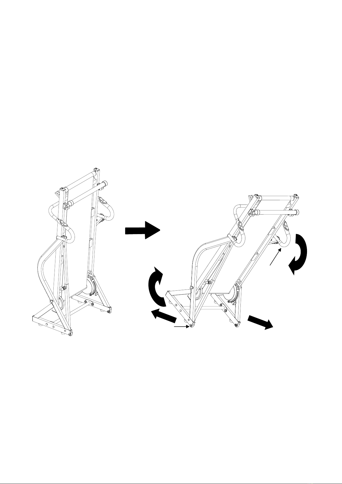
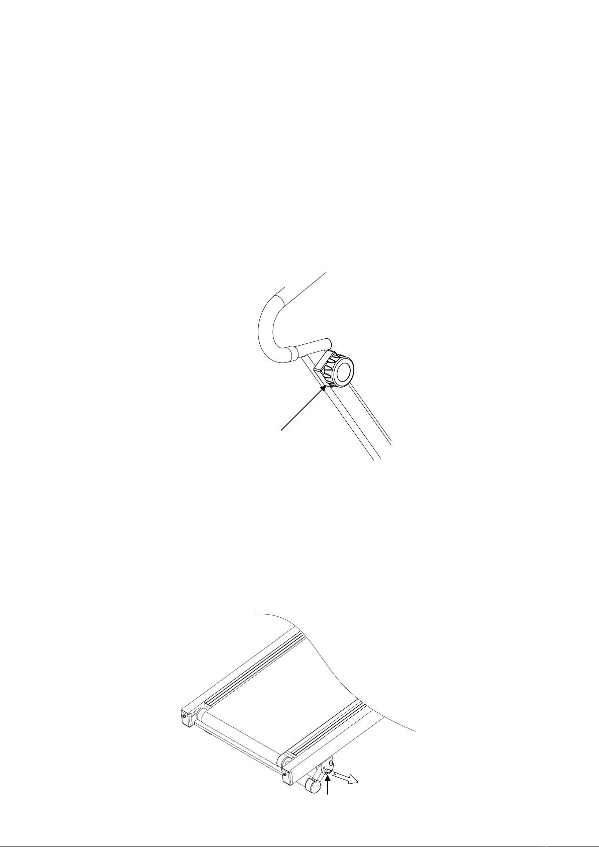
MOVING THE TREADMILL
The unit can be carefully tilted onto its Wheels for easy moving and storage.
With the treadmill in the folded locked position, firmly grasp the both Handlebars with both
hands. Next, carefully tilt the treadmill back until it rolls freely on the Wheels.
CAUTION: Do not attempt to move the treadmill while it is in the unfolded
position.
Handlebar
Wheel
14
ADJUSTMENTS
Adjusting the Tension Control Knob
To increase the tension, turn the Tension Control Knob in a clockwise direction.
To decrease the tension, turn the Tension Control Knob in a counterclockwise direction.
Tension Control Knob
Locking Pin
15
Adjusting the Incline Adjustment Frame
Place one hand on the rear end of the Main Frame. Lift the rear end of the Main Frame up
and then remove the locking Pins from the Main Frame and Incline Adjustment Frame.
Adjust the Incline Adjustment Frame to the desired position and insert the Locking Pins into
the holes on the Main Frame and Incline Adjustment Frame that were removed.
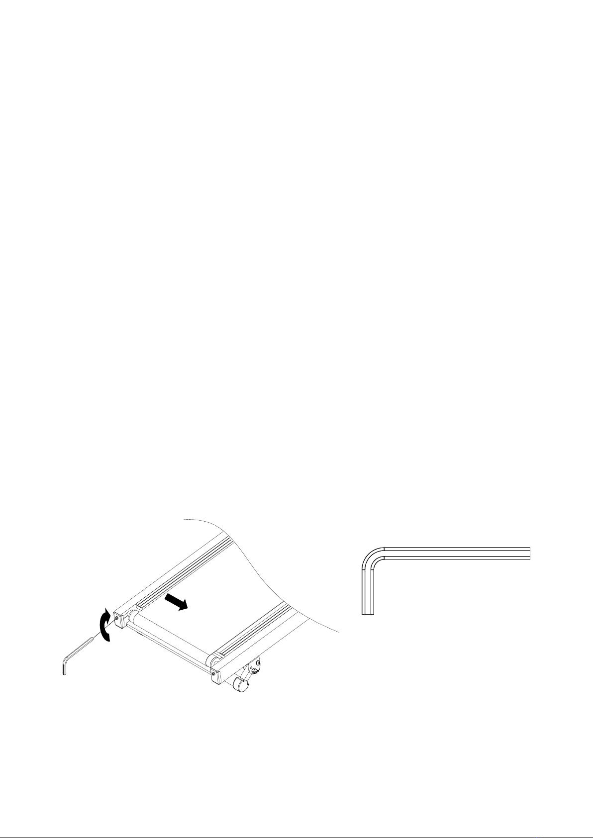
Adjusting the Running Belt
The running belt is initially set and adjusted at the factory. However it may come loose
during transportation and/or during use. It is recommended that the user run on the
center
of the running belt. After prolonged use, the belt will begin to stretch out. It is suggested
that the user always to walk or run on the central area. This will prevent the belt shifting
off
the center.
If the running belt begins to shift to the left, the user can stand on the Main Frame and hold
the handlebar with both hands. Then use your right foot to run on the right side of the
running belt. You should see the running belt start to correct itself by moving back towards
the center. However, if the running belt is still shifting to the left, use the Allen Wrench
provided and turn the left Rear Roller Adjustment Bolt 1/2 turn in a clockwise direction.
Then try running on the center of the running belt again. If the running belt is still shifting
to the left, turn the left Rear Roller Adjustment Bolt another 1/4 turn in the clockwise
direction. Then try running on the center of the running belt again. You should see the
belt start to correct itself by moving back towards the center. Repeat this procedure until
the running belt is centered.
Tool:

16
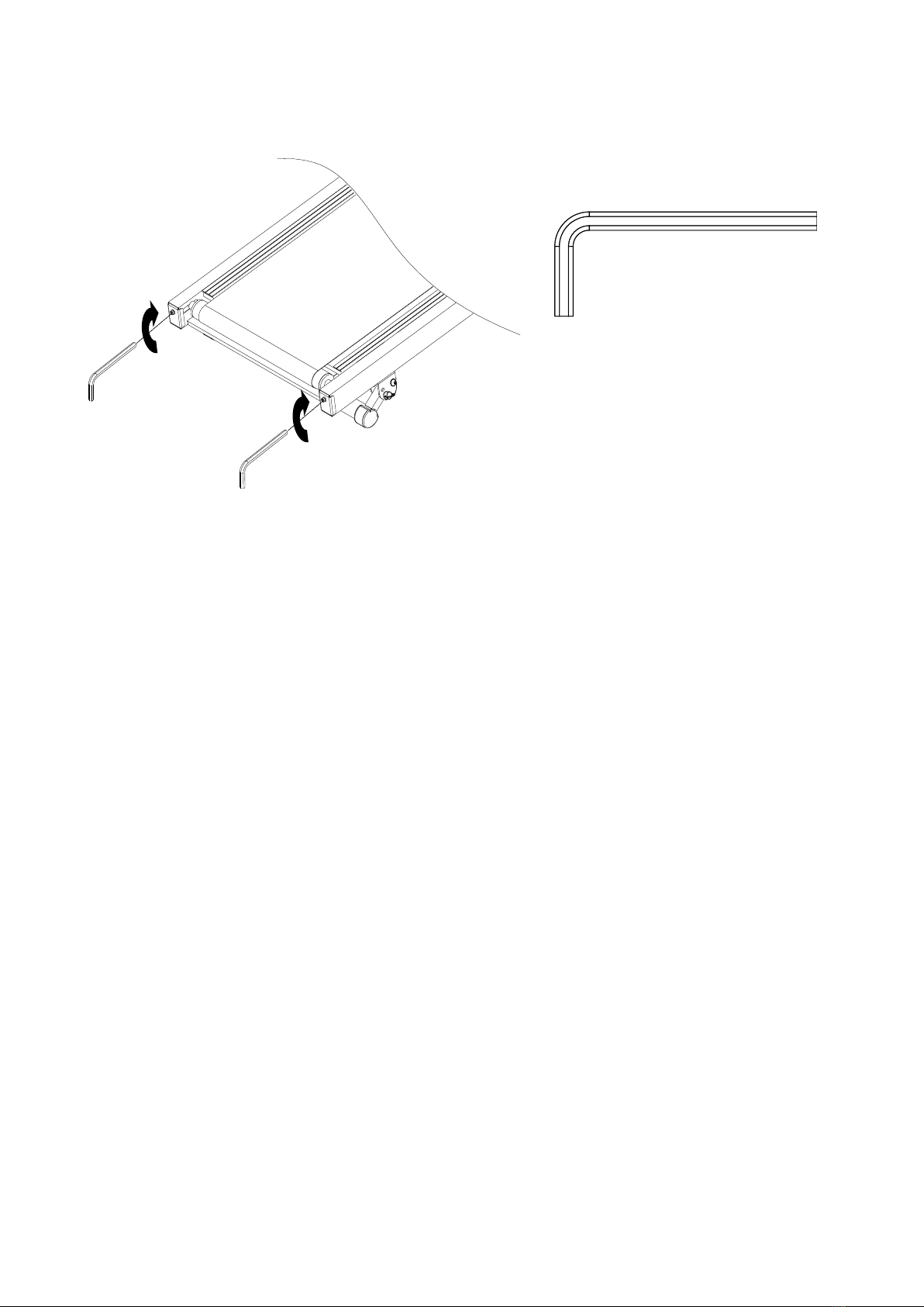
If the running belt begins to shift to the right, the user can stand on the Main Frame and
hold
the handlebar with both hands. Then use your left foot to run on the left side of the
running
belt. You should see the running belt start to correct itself by moving back towards the
center. However, if the running belt is still shifting to the right, use the Allen Wrench
provided and turn the right Rear Roller Adjustment Bolt 1/2 turn in a clockwise direction.
Then try running on the center of the running belt again. If the running belt is still shifting
to
the right, turn the right Rear Roller Adjustment Bolt another 1/4 turn in the clockwise
direction. Then try running on the center of the running belt again. You should see the
belt start to correct itself by moving back towards the center. Repeat this procedure until
the running belt is centered.
If the running belt is slipping during use, then use the Allen Wrench provided and turn both
left and right Rear Roller Adjustment Bolts 1/4 turn in the clockwise direction. You should
now run on the running belt to determine if the running belt is still slipping. Repeating the
Allen Wrench #5
Tool:
17
above procedure until the running belt is not slipping.
MAINTENANCE
Cleaning
The magnetic treadmill can be cleaned with a soft clean damp cloth. Do not use abrasives
or solvents on plastic parts. Please wipe your perspiration off the treadmill after each use.
Be careful not to get excessive moisture on the computer display panel as this might cause
an electrical hazard or electronics to fail.
Please keep the magnetic treadmill, especially the computer console out of direct sunlight
to
prevent screen damage.
Please inspect all assembly bolts, nuts, and screws on the machine for proper tightness
every week.
Storage
Store the magnetic treadmill in a clean and dry environment away from children.
TROUBLESHOOTING
PROBLEM: Treadmill running belt slips or is not centered on rear roller.
SOLUTION: Refer to “Adjusting the Running Belt” section on page 15.
PROBLEM: There is no display on the computer console.
SOLUTION: Remove the computer console and verify the wires that come from the
computer console are properly connected to the wires that come from the handlebar.
SOLUTION: Check the batteries are correctly positioned and battery springs are in proper
contact with batteries.
SOLUTION: The batteries in the computer console may be dead. Replace with new
batteries.

18
PROBLEM: There is no heart rate reading or heart rate reading is erratic / inconsistent.
SOLUTION: Make sure that the wire connections for the hand pulse sensors are secure.
SOLUTION: To ensure the pulse readout is more precise, please always hold on to the
handlebar grip sensors with both hands instead of just with one hand when you try to test
your heart rate figures.
SOLUTION: Avoid gripping the hand pulse sensors too tight. Try to maintain moderate
pressure while holding onto the hand pulse sensors.
PROBLEM: The treadmill makes a squeaking noise when in use.
SOLUTION: The bolts may be loose on the treadmill. Please inspect all of the bolts and
tighten any loose bolts.
If the above troubleshooting section does not fix the problem, discontinue use the
magnetic treadmill.
PLEASE CONTACT YOUR LOCAL DEALER FOR
SUPPORT.
WARM UP AND COOL DOWN ROUTINE
The WARM-UP is an important part of any workout. The purpose of warming up is to
prepare your body for exercise and to minimize injuries. Warm up for two to five minutes
before aerobic exercising. It should begin every session to prepare your body for more
strenuous exercise by heating up and stretching your muscles, increasing your circulation
and pulse rate, and delivering more oxygen to your muscles.
COOL DOWN at the end of your workout, repeat these exercises to reduce soreness in
tired muscles. The purpose of cooling down is to return the body to its resting state at the
end of each exercise session. A proper cool-down slowly lowers your heart rate and
allows blood to return to the heart.
HEAD ROLLS
Rotate your head to the right for one count, you should feel a
stretching sensation up the left side of your neck. Then rotate your
head back for one count, stretching your chin to the ceiling and
letting your mouth open. Rotate your head to the left for one count,
then drop your head to your chest for one count.
SHOULDER LIFTS
Lift your right shoulder toward your ear for one count. Then lift your
left shoulder up for one count as you lower your right shoulder.
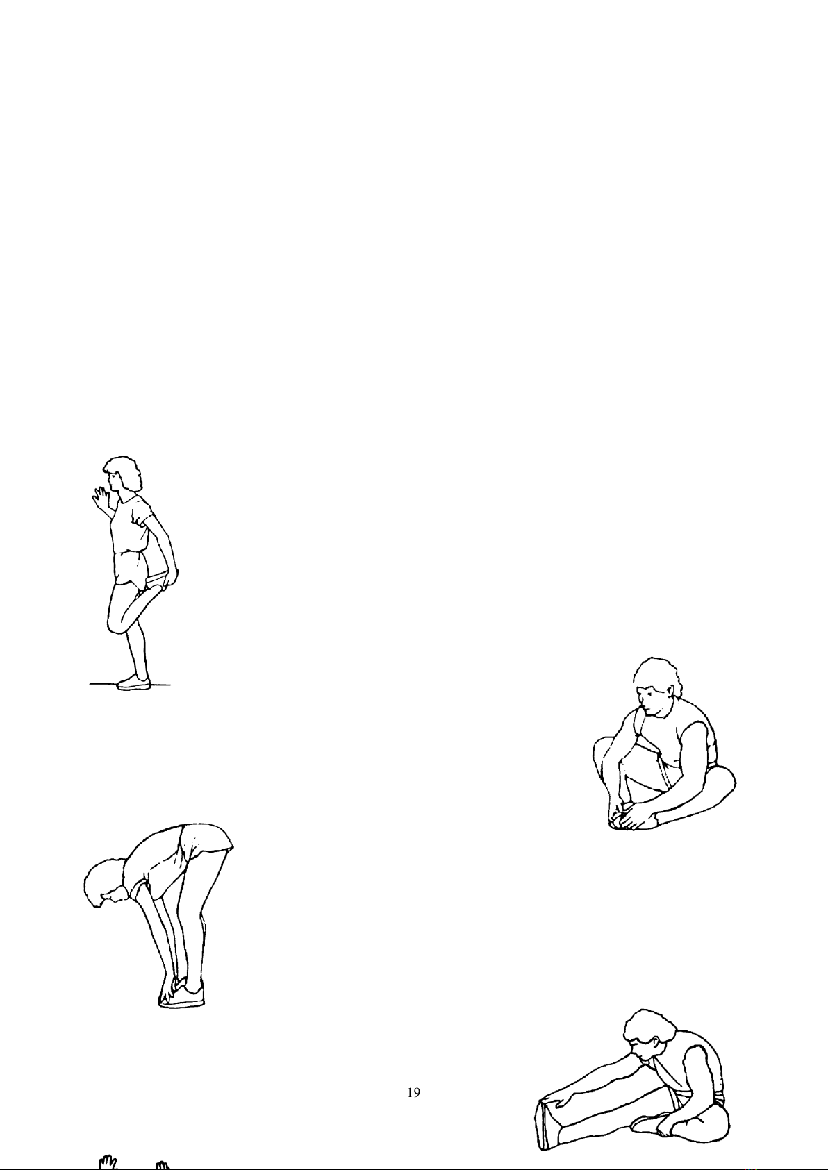
19
QUADRICEPS STRETCH
With one hand against a wall for balance, reach behind you and pull
your right foot up. Bring your heel as close to your buttocks as
possible. Hold for 15 counts and repeat with left foot.
HAMSTRING STRETCHES
Extend your right leg. Rest the sole of your left foot
against your right inner thigh. Stretch toward your toe
as far as possible. Hold for 15 counts. Relax and
then repeat with left leg.
INNER THIGH STRETCH
Sit with the soles of your feet together and your knees pointing
outward. Pull your feet as close to your groin as possible.
Gently push your knees toward the floor. Hold for 15 counts.
Table of contents
Other SPARTAN sport Treadmill manuals

Popular Treadmill manuals by other brands


DKN technology
DKN technology T 775 manual
ICON Health & Fitness
ICON Health & Fitness PFTL13820.0 user manual

Sears
Sears Pro-Form CROSS WALK owner's manual

TECHFIT
TECHFIT MT95 owner's manual

ICON Health & Fitness
ICON Health & Fitness PRO-FORM PRO 2500 user manual

Weslo
Weslo Cadence 630 Bedienungsanleitung