Spartan 81 User manual

M o d e l 8 1
Owners Manual
( 8 0 0 ) 4 3 5 - 3 8 6 6
SPARTAN TOOL L.L.C.
RecordtheSerialNumberofyour
Model 81
andgivethenumbertothefactory
whenordingparts.
SerialNumber..............................................
Whenordering,specifyquantityanditemnumbers
ALLPRICESNET,F.O.B.FACTORY,AND
SUBJECTTOCHANGEWITHOUTNOTICE

Page2
Table of Contents
OPERATING SECTION
How to Assemble....................................................................................................3
Operating Instructions.............................................................................................3
How to Repair 1/4” and 5/16” Cables.....................................................................4
Operating a Power Driven Cleaning Tool................................................................4
How to Install Cable in Model 81 ............................................................................5
Safety Instructions .............................................................................................. 6-7
PARTS & ACCESSORIES SECTION
Power Unit BSP04703300 ................................................................................. 8-9
Control Box ..................................................................................................... 10-11
Wiring Diagram .....................................................................................................11
Drum Unit ........................................................................................................12-13
Cables for Model 81 ....................................................................................... 14-15

Page3
How to Assemble
Removedrumandpowerunitfromcartons.
Step 1 Set power unit in verticalposition.(Seepictureonfrontpage)
Step 2 Mount drum on power unit. Lock drum to power unit by tightening (2) thumb screws. (Thumb screw
shouldermustenterholeincollarbeforetightening.)
Step 3 Loosen (3) wing nuts onmotormountplate.PutV-beltaroundpulleyanddrum.Movemotormounting
plateuntilV-beltisfirm. If thebeltistootight,machinewill notoperate.Tighten(3)wingnuts.
Operating Instructions
1. Insert proper size ofcableinmachine.Useopenhookcablesinupto11/2”lines,use5/16” innercore cable for
11/2”to 2” lines.
WE DO NOT RECOMMEND USING YOUR 1/4” CABLE IN LINES LARGER THAN 1 1/2” IN DIAMETER.
2. Place unit closetopipeopening(ideally12”ifpossible).
3. Pull out enough cabletoenterwasteline or cross bar.
4. PositionswitchinForward(F)position.Don’treverse motororuseReverseActionSwitchuntilmachinecomes
todead stop andthenonly to remove cablethroughcross bar.
5. Depress foot switch pedal,causingcabletorotatethroughcross bar or into pipeopening.(Forwardonly).
6. Take6”to8”lengthofcable,andslowlyfeeditintothelinegivingthecabletimetoroundfittingsandtoremove
stoppage.
7. Whenmotorslowsup,indicatingaloadonsame,pullcablebackabitandstartmovingitforwardsandbackwards.
Thisreciprocatingactionkeepsthecablerotating- keepscablefromgetting“hung-up”-themaincause ofcable
kinkageorbreakage.
8. If cable gets “hung-up”, stop your machine and reverse the direction of same through Reverse Switch, pulling
back as you do so to free working end of cable.
WARNING: Do not use Reverse Switch until you motor unit comes to dead stop!
9. Repeat this action as often as necessary tocleantheline.
10. When jobiscompleted, feed all cablebackinto drum 6” to8”at a time -DON’Ttake long bites.
11. You must reverse rotation of the drum to removecablethroughacrossbar.
12. Youmaydrainthedrumofexcessliquidsbyremovingthedrainplugwhichisthesmallerhexboltonthebackof
thedrum.

Page4
How to Repair 1/4” and 5/16” Cables
All1/4”and5/16”cables canberepairedwithareplacableend. Ifyoukinkyoucable,cutthecable offatthekinked
portion.Grindtheend ofsametoprovidealead thread.Now,pickupyourrepairendandthreadsameontheregular
cable,asyouwouldanutonabolt,turning same about three turns,whichwillfastenittothecablesecurely.Repair
endscan be purchased.
Operating a Power Driven Cleaning Tool
1. Stayclosetopipeopening,(ideally12”ifpossible)duringoperationsespeciallywhenroundingfittingsorremoving
stoppageinlines.
2. Moveyourcablebackwardsandforwardsconstantlywhenyougetintostoppage,therebypreventingyourcable
fromgetting“hung-up”,causingunnecessarykinkage.Remember-arotatingcablecannotkinkorbreak.Kinkage
ofcabletakesplaceonlywhentheworkingendofthecablegets“hung-up”andyoukeepon twisting the other
end.
3. Don’t attempt to roundfittingsorremovestoppage until your drumreachesfullspeed.It is the rotation ofthe
cablethatenables it to either(a)roundfittings, or (b) removestoppage-NOTpushpower.
Page5
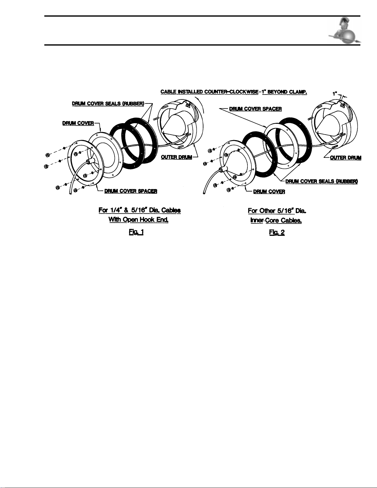
How to Install Cable in Model 81
1. Position drum unitin a verticalposition.Remove (6) nuts,washers, drum cover,drum cover spacer, and (2)
drumcoverseals.
2. Assembledrumcoverspacerand(2)sealstoouter drumasrequiredforvariouscables.See Figure1andFigure
2.
3. Insert cable throughdrumcoverasillustratedinFigure1.
4. Place end of cable in outer drum. Slide cable under clamp. Cable should enter clamp in counter-clockwise
direction and extend approximately 1” beyond clamp. See Figure 1. tighten clamp screw.
5. Place drum cover on outer drum assembly and secure with (6) nuts and washers. Assemble all (6) nuts,
tightening all nuts a little at a time; about 3 times around. Then give nuts a final tightening.
6. Feed remainder of cable into drum while drum is operating in forward only.
Page6
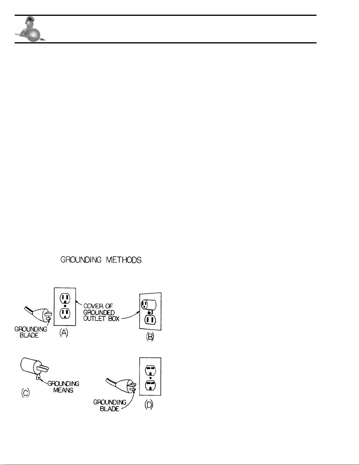
Safety Instructions
A. ForAllGroundedTools
1. GroundingInstructions
This tool should be grounded while in use to
protect the operator from electric shock. The
tool is equipped with a 3-conductor cord and
3-prong grounding type plug to fit the proper
grounding type receptacle. The green (or
green and yellow) conductor in the cord is
the grounding wire. Never connect the green
(or green and yellow) wire to a live terminal.
If your unit is for use on less than 150V, it
has a plug that looks like that shown in sketch
(A). If it is for use on 150 to 250 V, it has a
plug that looks like that shown in sketch (D).
An adapter, see sketches (B) and (C), is
availablefor connecting sketch(A) type plugs
to a 2-prong receptacles, except in Canada.
The green-colored rigid ear, lug, or the like,
extendingfrom the adaptermust be connected
to a permanent ground, such as a properly
grounded outlet box. No adapter is available
for a plug as shown in sketch (D).
2. ExtensionCords
Useonly3-wireextensioncordsthathave3-prong
grounding-typeplugsand3-polereceptaclesthat
acceptthetool’splug.Replaceorrepairdamaged
cords.
B. ForAllDouble-InsulatedTools:
ReplacementParts
Whenservicinguseonlyidenticalreplacementparts.
C. ForAllTools:
1. Keep WorkArea Clean
Clutteredareasandbenches inviteinjuries.
2. ConsiderWorkArea Environment
Don’texposepower tools to rain.
Keepworkareawell lit.
Donotusetool inpresenceofflammableliquids
orgases.
2A.GuardAgainstElectricShock
Preventbodycontactwithgroundedsurfaces.For
example; pipes, radiators, ranges, refrigerator
enclosures.
3. KeepChildrenAway
Donotletvisitors contacttoolorextensioncord.
Allvisitorsshouldbekeptawayfromworkarea.
4. Store IdleTools
When not in use, tools should be stored in dry,
and high or locked-up places - out of reach of
children.
5. Don’t Force Tool
It will do the job better and safer at the rate
for which it was intended.
6. UseRightTool
Don’t force small tool or attachment to do the
job of a heavy-duty tool.

Page7
Safety Instructions
7. Dress Properly
Do not wear loose clothing or jewelry. They
can be caught in moving parts. Rubber gloves
and non-skid rubber foot-wear are
recommended when working outdoors.
Wear protective hair covering to contain long
hair.
8. Use Safety Glasses
Also use face or dust mask if cutting operation
is dusty.
9. Don’t Abuse Cord
Never carry tool by cord or yank it to
disconnect from receptacle. Keep cord from
heat, oil, and sharp edges.
10. Secure Work
Use clamps or a vise to hold work. It’s safer
than using your hand and it frees both hands
to operate tool.
11. Don’t Overreach
Keep proper footing and balance at all times.
12. Maintain Tools With Care
Keep tools sharp and clean for better and safer
performance.
Follow instructions for lubricating and
changing accessories.
Inspecttool cords periodically andifdamaged,
have repair by authorized service facility.
Inspect extension cords periodically and
replace if damaged.
Keep handles dry, clean, and free from oil and
grease.
13.DisconnectTools
When not in use, before servicing, and when
changing accessories, such as blades, and
cutters.
14.RemoveAdjustingKeysandWrenches
Form habit of checking to see that keys and
adjusting wrenches are removed from tool
before turning it on.
15. Avoid Unintentional Starting
Don’t carry plugged-in tool with finger on
switch. Be sure switch is off when plugging
in.
16. Outdoor Use Extension Cords
Whentoolis used outdoors, useonlyextension
cordsintendedfor use outdoors and somarked.
17. Stay Alert
Watch what you are doing. Use common
sense. Do not operate tool when you are tired.
18. Check Damaged Parts
Before further use of the tool, a guard or other
part that is damaged should be carefully
checked to determine that it will operate
properly and perform its intended function.
Check for alignment of moving parts, binding
of moving parts, breakage of parts, mounting,
and any other conditions that may affect its
operation. A guard or other part that is
damaged should be properly repaired or
replacedby an authorized servicecenterunless
otherwise indicated elsewhere in this
instruction manual.
Have defective switches replaced by
authorized service center.
Do not use tool if switch does not turn it on
and off.
Page8
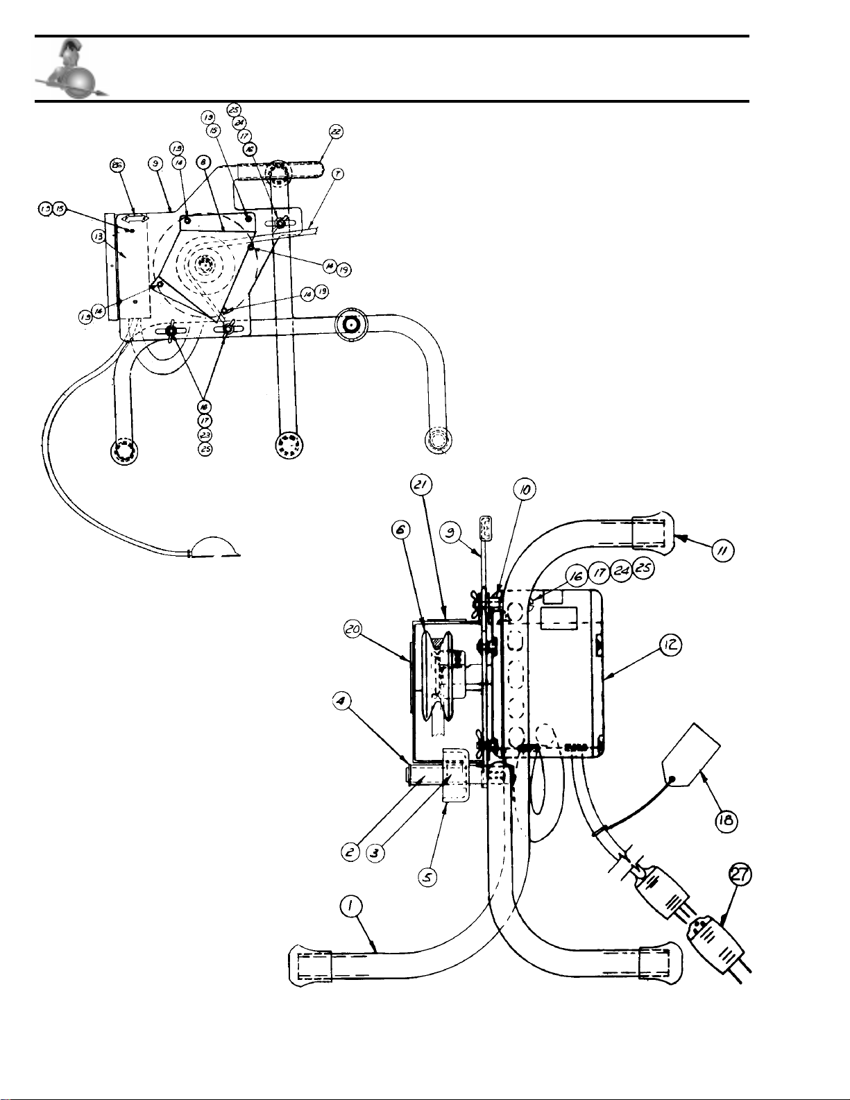
BSP04703300 Model 81 Power Unit

Page9
BSP04703300 Model 81 Power Unit
Item
Number PartNumber Description
1 ASP04733400 Frame Assy. Includes item 2, 3, 4, 5, 10, 11, 16,
17, 23, 24 & 25
2 AXX03421300 Bronze Bearing
3 ASP04700400 Flanged Bearing
4 XXX02822500 Retainer Ring
5 ASP04700300 Shaft Collar
6 ASP04700600 Sheave
7 ASP04233200 V-Belt
8 ASP04733500 Sheave Guard Assy, Includes items 20 & 21
9 ASP04733600 Motor Mount Plate Assy., Includes items 22 & 26
10 ASP04700700 Space 3/8" O.D. x .058 Wall x 11/16"
11 ASP04699800 Tip Mounting
12 DSP04708700 Motor and Terminals Assembly
13 See Page 4 for Control Box
14 XXX03850101 Kep Nut #10 - 32
15 XXX00125801 Machine Screw#10 - 32 x 3/8"
16 XXX0140501 Wing Nut 1/4" - 20
17 XXX0076330 Flat Washer 1/4"
18 ASP02828800 Caution Tag
19 XXX04725200 AcornNut #10 - 32
20 ASP04715000 Spartan Label
21 DSP04703600 Cover Position Label
22 ASP04715200 Handle Grip
23 XXX00128601 Round Hd. Mach. Screw 1/4" - 20 x 1 3/4"
24 XXX03337601 Round Hd. Mach. Screw 1/4" - 20 x 2 1/2"
25 XXX00137301 HexNut 1/4" - 20
26 ASP04714900 Switch Direction Label
27 ASP02768901 Ground Wire Adapter

Page10
Control Box
Item
Number Part Number Description
1 CSP4402200 Control Box Weldment
2 ASP04225800 Toggle Switch
3 ASP04229900 Capacitor
4 ASP04230900 Capacitor Clamp
5 ASP04230000 Terminal Cap
6 XXX01921801 Rd. Hd Slotted Mach. Scr. #8-32 x 1/2" Lg.
7 XXX03312001 Kep Nut#8 - 32
8 CSP44002100 Control Box Cover
9 XXX03394400 Sheet Metal Screw #6 x1/4" Ph (A) Pt.
10 ASP44002600 Pressure Switch
11 ASP04704500 StrainRelief (Bushing) Power Cord
12 ASP44002500 StrainRelief (Bushing) Motor Cord
13 ASP04652700 Crimp Type Hose Clamp
14 ASP04577100 Air Hose
15 ASP04576900 Pressure Transmitter
16 ASP44055500 Ass'y, Air Foot Switch (Includes 13, 14 & 15)
17 DSP04701701 Power Cord & Terminals
18 ASP44003000 Jumper Wire Assy. (Black - 3 3/4" Lg.)
19 ASP04234400 Jumper Wire Assy. (Yellow - 5" Lg.)

Page11
Control Box
Wiring Diagram
Page12
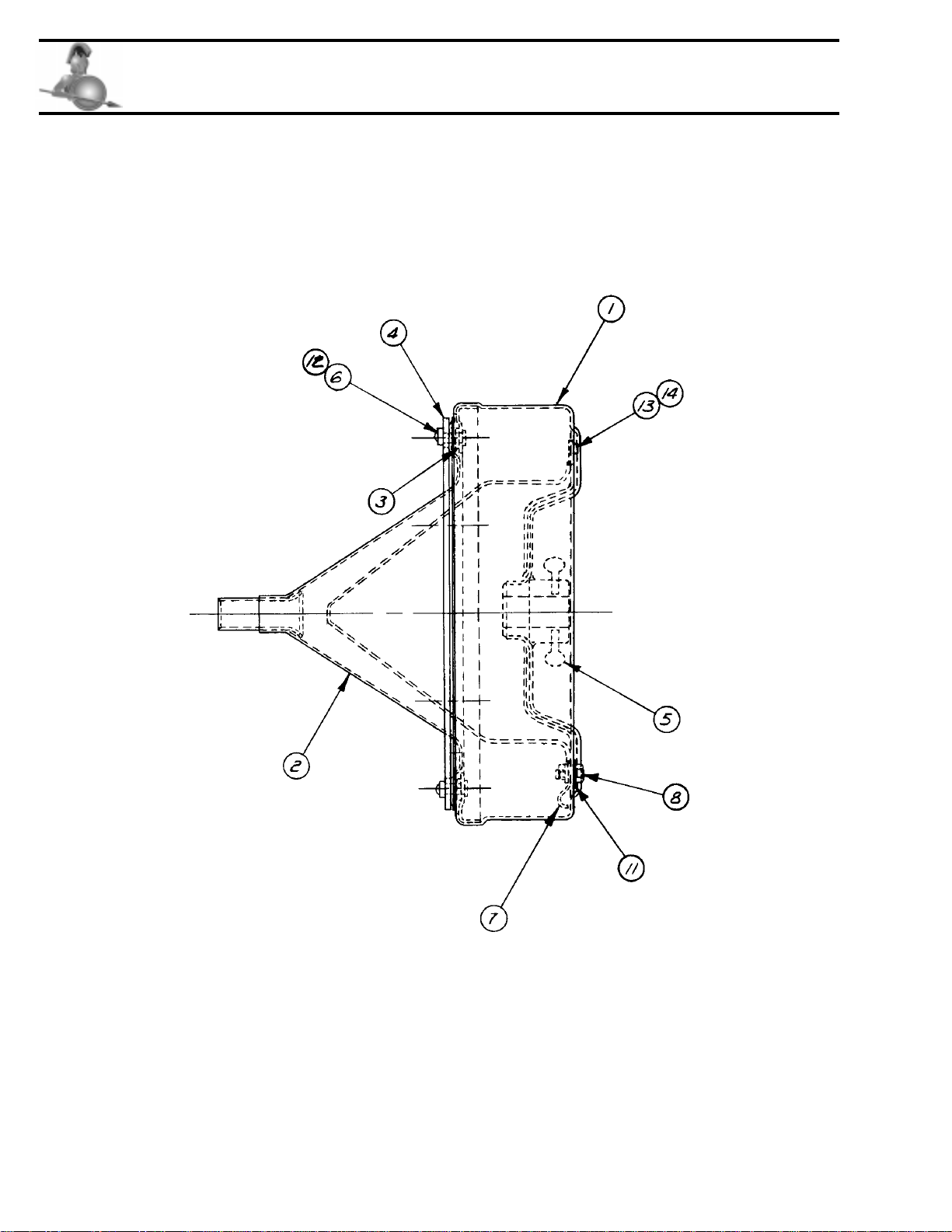
Drum Unit For Model 81

Page13
Drum Unit For Model 81
Item
Number Part Number Description
BSP04722600 Drum Unit Complete Assy.
1 CSP04726900 Outer Drum & Flange Assy. includes items
5, 7, 8, 11,13 & 14
2 CSP04727000 Drum Cover Assy. includes items 9 & 10
3 CSP04720300 Drum Cover Seal
4 CSP04720400 Drum Cover Spacer
5 ASP04701400 Thumb Screw
6 XXX04725200 AcornNut #10 - 32
7 ASP04725300 Cable Clamp Assy
8 XXX00114901 Hex Head Cap Screw 5/16" - 18 x 3/4"
9 ASP04714800 Warning Label
10 ASP04714700 Drum Label
11 XXX02825101 Flat Washer 5/16"
12 XXX01588200 Flat Washer #10
13 XXX04728200 Hex Head Cap Screw 1/4 - 20 x 3/8
14 ASP04707700 Rolled Collar 1/4"

Page14
Spartan Swedish Steel Cables Without Inner Core
Flexibleopenhookendenables operatortothreadcablethroughcrossbars -eliminatingnecessityofremovingtrap
-todoa thorough job quickly.Onerepairhookfurnished with each cable.
¼”OpenHookEndCableDesignedforrodding1¼”lines only.
DSP04212102 ¼” x 25'
DSP04212103 ¼” x 30'
DSP04212104 ¼” x 35'
DSP04212105 ¼” x 50'
5/16"OpenHookEndCableDesignedforrodding1¼”to1½”lines, such as those leading from lavatories, bath
tubs,showerstalls.
DSP04212402 5/16" x 25'
DSP04212403 5/16" x 30'
DSP04212404 5/16" x 35'
DSP04212405 5/16" x 50'
Spartan Swedish Steel Inner-Core Drop-Head Cable
ASP44104301 ¼” x 25' D.H.*
ASP44104302 ¼” x 35' D.H.*
CSP03449002 5/16" x 25'
CSP03449003 5/16" x 30'
CSP03449004 5/16" x 35'
CSP03449005 5/16" x 50'
5/16"Multi-PurposeInner-CoreCable. Designed for rodding 1¼” to 1½” lavatory, sink line waste andforlight
dutyin2"lines.
PartsFor5/16" Inner-CoreCable:
ASP02867200 Blade,¾”Wide XXX02882200 ExpansionPin¼” x 5/8"
ASP02867300 Blade,1"Wide XXX02827700 AllenKey for Blades
ASP02871100 DropHeadAssembly XXX02827400 Socket Set Screw for Blades
ASP02814700 Bagofpartsfor5/16"including
drophead
Cables For Model 81
Page15
Cables For Model 81
Repair Bulbs
For5/16"Inner-Core Cables:
ASP02885200 RepairBulb
Repair Hooks
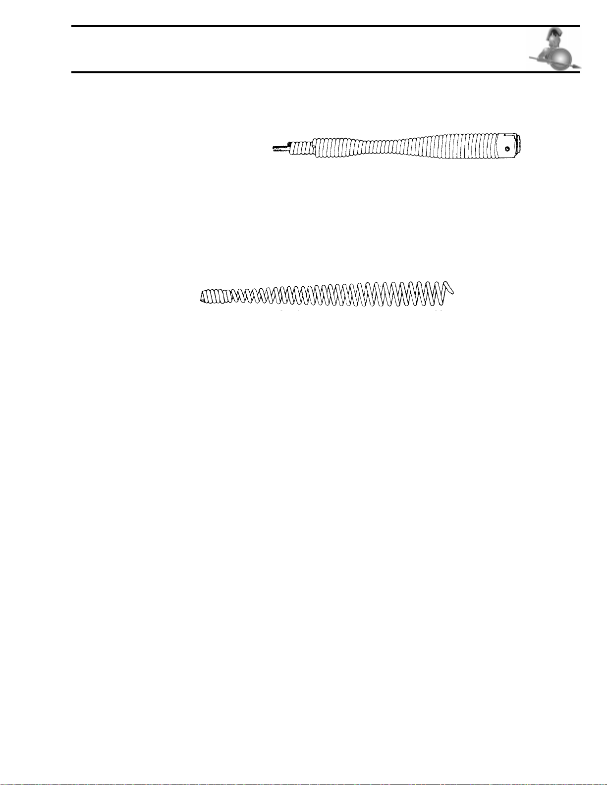
How to Use Repair Hook or Repair Bulbs
Ifcableiskinked,simplyremovekinkedportionbycuttingitoffatapointabout1"backofbentsection.Attach
RepairHookbythreadingitovercableendaboutfourturns.
ASP02789700 for¼” Cable RightHandWound
DSP02789800 for5/16" Cable RightHandWound
* - Not Inner-Core

SPARTAN TOOLL.L.C.
1506 W. Division Street
Mendota, IL 61342
(815)539-7411 u(800)435-3866 uFax (815)539-9786
spartantool.com
04726800 op AR3/11/98
04716700 pa AR6/11/98
AR7/7/00
ONEYEAR WARRANTY
SpartanTool warrants itsequipmenttofreefromdefectsinmaterialandworkmanshipforoneyearfromthe date
ofpurchase. To obtainwarrantyservice,apurchasershouldnotifySpartanToolinwriting,attheaddressprovided
below,withinthewarranty period,andSpartanToolwilldirectwheretotakeor sendtheequipmentforservice. If
thedefectis covered by thewarranty,SpartanTool will repair orreplace,at its option, the defectiveequipment,
withoutcharge forlaborormaterials. (Freightandinsurancearethepurchaser’sresponsibility.)
Thiswarrantyislimitedtotheoriginalretailpurchaserandisnottransferable. SpartanToolassumesnoresponsibility
fordamageduetoaccident,neglect,abuse,tamperingor misuse,nordamagefromrepairs oralterationsbyothers.
This warranty does not cover damage to the equipment resulting from the use of placement parts other than
SpartanToolparts.
SpartanTool’ssoleobligationand theoriginalretailpurchaser’sexclusiveremedyunderthiswarrantyshallbefor
repairorreplacementasdescribedabove. ALLOTHERWARRANTIES,WHETHEREXPRESSORIMPLIED,
INCLUDINGBUTNOTLIMITEDTOIMPLIEDWARRANTIESOFMERCHANTABILITYANDFITNESS
FOR A PARTICULAR PURPOSE ARE DISCLAIMED. IN NO EVENT SHALL SPARTAN TOOL BE
LIABLEFORANYINCIDENTALORCONSEQUENTIALDAMAGES.
SPARTANTOOLL.L.C.
MENDOTA, ILLINOIS 61342
Other manuals for 81
1
Table of contents


