Spartan 1012 User manual

Programmable 1012
Elliptical Cross Trainer
(pc)
ITEM NO: 1012

OWNER S MANUAL
IMPORTANT: Read all instructions carefully before using this product. Retain this
owner’s anual for future reference.
The specifications of this product ay vary fro this photo, subject to change without
notice.
TABLE OF CONTENTS
IMPORTANT SAFETY INSTRUCTIONS ------------------------------------------- 2
PARTS LIST ------------------------------------------------------------------------------- 3
HARDWARE LIST ----------------------------------------------------------------------- 5
TOOLS -------------------------------------------------------------------------------------- 5
OVERVIEW DRAWING ----------------------------------------------------------------- 6
ASSEMBLY INSTRUCTIONS --------------------------------------------------------- 7
OPERATING THE COMPUTER ------------------------------------------------------ 15
ADJUSTMENT ---------------------------------------------------------------------------- 19
MAINTENANCE -------------------------------------------------------------------------- 2
TROUBLESHOOTING ------------------------------------------------------------------ 2
WARM UP AND COOL DOWN ROUTINE ----------------------------------------- 21
2

IMPORTANT SAFETY INSTRUCTIONS
Basic precautions should al ays be follo ed, including the follo ing important
safety instructions hen using this equipment. Read all instructions before using
this equipment.
1. Read all instructions and follow it carefully before using this equipment. Make sure the
equipment is properly assembled and tightened before use.
2. Before exercise, in order to avoid injuring the muscle, warm-up exercises are
recommended.
3. Please make sure all parts are not damaged and fixed well before use. This equipment
should be placed on a flat surface when using. Using a mat or other
covering material on the ground is recommended.
4. Please wear proper clothes and shoes when using this equipment; do not wear clothes
that may catch any part of the equipment.
5. Do not attempt any maintenance or adjustments other than those described in this
manual. Should any problems arise, discontinue use and consult your local dealer.
6. Be careful when step on or leave the pedal always hold the handlebars first. Make the
pedal at your side at the lowest position, step on the pedal, and stride over the main
frame then step on the other pedal. When using, please hold the handlebar by hands,
make the pedals running smoothly by push or pull handlebars, then run the equipment
regularly by cooperation of hands and feet. After exercise, please also make one
pedal at the lowest position and leave your foot on the higher pedal first and then
another.
7. Do not use the equipment outdoors.
8. This equipment is for household use only. It is not a commercial model.
9. Only one person at a time should use this equipment.
3

1 . If you feel any chest pains, nausea, dizziness, or short of breath, you should stop
exercising immediately and consult your physician before continuing.
11. Care should be taken in mounting or dismounting the equipment.
12. Do not allow children to use or play on the equipment. Keep children and pets away
from the equipment while in use. This machine is designed for adults use only. The
minimum free space required for safe operation is not less than two meters.
13. The maximum weight capacity for this product is 12 kgs.
WARNING: Before beginning any exercise program consult your
physician. This is especially important for the people ho are over 35 years old or
ho have pre-existing health problems. Read all instructions before using any
fitness equipment.
CAUTION: Read all instructions carefully before operating this product.
Retain this O ner’s Manual for future reference.
PARTS LIST
No. Description Qty No. Description Qty
1 Handrail End Cap Ø32x1.5 2 19 Hexagon Socket Pan Head Cap
Bolt Ø1 x46
2
2L Left Handrail Ø32x1.5 1 2 Big Washer Ø6xØ18x1.5 2
2R Right Handrail Ø32x1.5 1 21 Cross Recessed Pan Head Bolt
M6x15
6
3 Handrail Foam Grip
Ø31xØ37x48
2 22 Hexagon Bolt M6x4 6
4 Cross Recessed Pan Head
Tapping Screw ST4.2x12
8 23L Left Foot Pedal 1
5 Left Handrail Arm Cover-A 1 23R Right Foot Pedal 1
6 Nylon Nut M6 16 24 Washer Ø6xØ12x1 7
7 Curve Washer Ø6xØ12x1 4 25 Hexagon Bolt M8x5 2
8 Carriage Bolt M6x35 4 26 Powder Metal Bushing
Ø18xØ8x1
4
9 Screw ST4.2x2 22 27L Left Foot Bar 4 x25x1.5 1
1 Left Handrail Arm Cover-B 1 27R Right Foot Bar 4 x2 x1.5 1
4

11 Hexagon Socket Pan Head Cap
Bolt M8x2
4 28 Washer Ø16xØ8x1.5 2
12 Spring Washer Ø8 1 29 Nylon Nut M8 2
13 Big Washer Ø8xØ25x2 4 3 Foot Bar Bracket Cover 2
14 Washer Ø38x16.5xδ3 4 31 Handlebar End Cap Ø28.6x1.5 2
15 Powder Metal Bushing
Ø38xØ32xØ19x14
8 32 Hand Pulse Sensor with Wire
L=75 mm
2
16L Left Handrail Arm Ø32x1.5 1 33 Hexagon Socket Pan Head Cap
Bolt M8x15
8
16R Right Handrail Arm Ø32x1.5 1 34 Curve Washer Ø16xØ8x1.5 2
17 Powder Metal Bushing
Ø14xØ1 x1
4 35 Cross Recessed Pan Head
Tapping Screw ST4.2x2
2
18L Front Foot Bar Cover-A 2 36 Handlebar Foam Grip
Ø33xØ27x36
2
18R Front Foot Bar Cover-B 2 37 Handlebar Ø28.6x2 1
PARTS LIST
No. Description Qty No. Description Qty
38 Computer SM-372 1 63L Left Cover 1
39 Extension Sensor Wire I
(L=11 mm)
1 63R Right Cover 1
4 Cross Recessed Pan Head Bolt
M5x1
4 64 Foot Bar Bracket Ø38x3 2
41 Front Decorative Cover for Front
Post
1 65 Plastic Spacer Ø38xØ19x4 2
42 Rear Decorative Cover for Front
Post
1 66 Crank Disk Ø391x21 2
43 Motor 1 67 Crank 4 x2 x3 2
44 Motor Tension Cable L=5 mm 1 68 Cross Recessed Pan Head
Tapping Screw ST4.2x15
16
45 Extension Sensor Wire
L=125 mm
1 69 Spring Clip Ø17x1. 2
5

46 Power Supply Wire L=3 mm 1 7 Wave Washer Ø28xØ17x .3 1
47 Front Post Ø6 x1.5 1 71 Bearing 6 3-2Z 2
48 Big Curve Washer Ø8xØ2 x2 1 72 Main Frame 8 x4 x2 1
49 Plastic Bushing Ø32x69 2 73L Left Plastic Cover 1
5 Right Handrail Arm Cover-A 1 73R Right Plastic Cover 1
51 Right Handrail Arm Cover-B 1 74 Rubber Cover 2
52 Transport Wheel Ø45x19 2 75 Sensor with Wire (L=3 mm) 1
53 Cross Recessed Pan Head Bolt
M6x35
2 76 Cross Recessed Pan Head
Tapping Screw ST2.9x12
2
54 Cap Nut M8 4 77 Hexagon Nut M6 2
55 Adjustable Leveler M1 2 78 Spring Washer Ø6 6
56 Carriage Bolt M8x65 4 79 Tension Bracket 31x3 xδ1 2
57 Front Left Stabilizer End Cap 1 8 Eyebolt M6x36 2
58 Front Stabilizer 1 81 Nut M1 x1x6 2
59 Front Right Stabilizer End Cap 1 82 Flywheel Ø26 1
6 Cross Recessed Pan Head
Tapping Screw ST4.2x25
11 83 Cross Recessed Pan Head Bolt
M6x1
1
61 Plastic Disc Cap 2 84 Bearing 6 -2Z 2
62 Nut M1 x1.25x6 2 85 Washer Ø1 xØ14x1 2
PARTS LIST
No. Description Qty No. Description Qty
86 Hexagon Socket Pan Head Cap
Bolt M8x25
1 92 Rear Left Stabilizer End Cap 1
87 Idler Arm 1 93 Rear Stabilizer 55x5 x1.5 1
88 Hexagon Socket Pan Head Cap
Bolt M8x1
1 94 Rear Right Stabilizer End Cap 1
89 Belt Pulley Ø26 1 95 Hexagon Nut M1 2
9 Belt PJ4 1 96 Hexagon Nut 1/2” 1
91 Plastic Screw Anchor Ø8x32 1 97 AC Adapter 1
HARDWARE LIST
6

(4) Cross Recessed Pan Head
Tapping Screw ST4.2x12
8 PCS
(6) Nylon Nut M6
1 PCS
(7) Curve Washer Ø6xØ12x1
4 PCS
(8) Carriage Bolt M6x35
4 PCS
(22) Hexagon Bolt M6x4
6 PCS
(24) Washer Ø6xØ12x1
6 PCS
(48) Big Curve Washer
Ø8xØ2 x2
4 PCS
(54) Cap Nut
M8
4 PCS
(56) Carriage Bolt
M8x65
4 PCS
TOOLS
7
Allen Wrench S6
1 PC
Multi Hex Tool with Phillips Screwdriver
S1 , S13, S14, S15
1 PC

OVERVIEW DRAWING
8

ASSEMBLY INSTRUCTIONS
1. Front and Rear Stabilizers Installation
Position the Front Stabilizer (58) in front of Main Frame (72) and align bolt holes.
Attach the Front Stabilizer (58) onto the front curve of the Main Frame (72) with two
Ø8xØ2 x2 Big Curve Washers (48), two M8 Cap Nuts (54), and two M8x65 Carriage Bolts
(56). Tighten cap nuts with the Multi Hex Tool with Phillips Screwdriver provided.
Position the Rear Stabilizer (93) behind the Main Frame (72) and align bolt holes.
Attach the Rear Stabilizer (93) onto the rear curve of the Main Frame (72) with two
Ø8xØ2 x2 Big Curve Washers (48), two M8 Cap Nuts (54), and two M8x65 Carriage Bolts
(56). Tighten cap nuts with the Multi Hex Tool with Phillips Screwdriver provided.
Hard are:
9
(48) Big Curve Washer
Ø8xØ2 x2
4 PCS
(54) Cap Nut
M8
4 PCS
(56) Carriage Bolt
M8x65
4 PCS
Tool:
Multi Hex Tool with Phillips Screwdriver
S10, S13, S14, S15

Allen Wrench S6
Tool:
2. Front Post Installation
Remove six M8x15 Hexagon Socket Pan Head Cap Bolts (33), six Ø8 Spring Washers
(12), and six Ø8xØ2 x2 Big Curve Washers (48) from the Main Frame (72). Remove bolts
with the S6 Allen Wrench provided.
Connect the Extension Sensor Wire (45) from the Main Frame (72) to the Extension Sensor
Wire I (39) from the Front Post (47).
Insert the Front Post (47) onto the tube of the Main Frame (72) and secure with six M8x15
Hexagon Socket Pan Head Cap Bolts (33), six Ø8 Spring Washers (12), and six Ø8xØ2 x2
Big Curve Washers (48) that were removed. Tighten bolts with the S6 Allen Wrench
10

provided.
11

3. Left/Right Handrail Arms, Left/Right Foot Bars, Left/Right Foot Pedals, Foot Bar
Covers-A/B, and Foot Bar Bracket Covers Installation
Remove one M8x2 Hexagon Socket Pan Head Cap Bolt (11), one Ø8 Spring Washer (12),
one Ø8xØ25x2 Big Washer (13), and one Ø38x16.5xδ3 Washer (14) from the left
horizontal
axis of the Front Post (47). Remove bolts with the S6 Allen Wrench Tool provided.
Attach the Left Handrail Arm (16L) onto the left horizontal axis of the Front Post (47) with
one M8x2 Hexagon Socket Pan Head Cap Bolt (11), one Ø8 Spring Washer (12), one
Ø8xØ25x2 Big Washer (13), and one Ø38x16.5xδ3 Washer (14) that were removed.
Tighten bolt with the S6 Allen Wrench provided.
12
Allen Wrench S6
Tools:
Multi Hex Tool with Phillips Screwdriver
S10, S13, S14, S15

Remove one M8x2 Hexagon Socket Pan Head Cap Bolt (11), one Ø8 Spring Washer (12),
one Ø8xØ25x2 Big Washer (13), and one Ø38x16.5xδ3 Washer (14) from the left Crank
(67). Remove bolt with the S6 Allen Wrench provided.
Attach the left Foot Bar Bracket (64) to the left Crank (67) with one M8x2 Hexagon Socket
Pan Head Cap Bolt (11), one Ø8 Spring Washer (12), one Ø8xØ25x2 Big Washer (13), and
one Ø38x16.5xδ3 Washer (14) that were removed. Tighten bolt with the S6 Allen Wrench
provided.
Attach the Left Foot Pedal (23L) onto the Left Foot Bar (27L) with three M6 Nylon Nuts (6),
three Ø6xØ12x1 Washers (24), and three M6x4 Hexagon Bolts (22). Tighten nylon nuts
with the Multi Hex Tool with Phillips Screwdriver provided.
Remove two ST4.2x2 Screws (9) from the front end of the Left Foot Bar (27L). Remove
screws with the Multi Hex Tool with Phillips Screwdriver provided.
Attach the Front Foot Bar Covers-A/B (18L, 18R) onto the front end of the Left Foot Bar
(27L) with two ST4.2x2 Screws (9) and one ST4.2x12 Cross Recessed Pan Head Tapping
Screw
(4). Tighten screws with the Multi Hex Tool with Phillips Screwdriver provided.
Remove one ST4.2x2 Screw (9) from the rear end of the Left Foot Bar (27L). Remove
screw with the Multi Hex Tool with Phillips Screwdriver provided.
Attach the Foot Bar Bracket Cover (3 ) onto the rear end of the Left Foot Bar (27L) with
one
ST4.2x2 Screw (9). Tighten screw with the Multi Hex Tool with Phillips Screwdriver
provided.
Repeat the same procedure for attaching the Right Handrail Arm (16R) onto the right
horizontal axis of the Front Post (47) and right Foot Bar Bracket (64) to the right Crank (67).
Hard are:
13
(22) Hexagon Bolt M6x4
6 PCS
(24) Washer Ø6xØ12x1
6 PCS
(6) Nylon Nut M6
6 PCS
(4) Cross Recessed Pan Head
Tapping Screw ST4.2x12
2 PCS
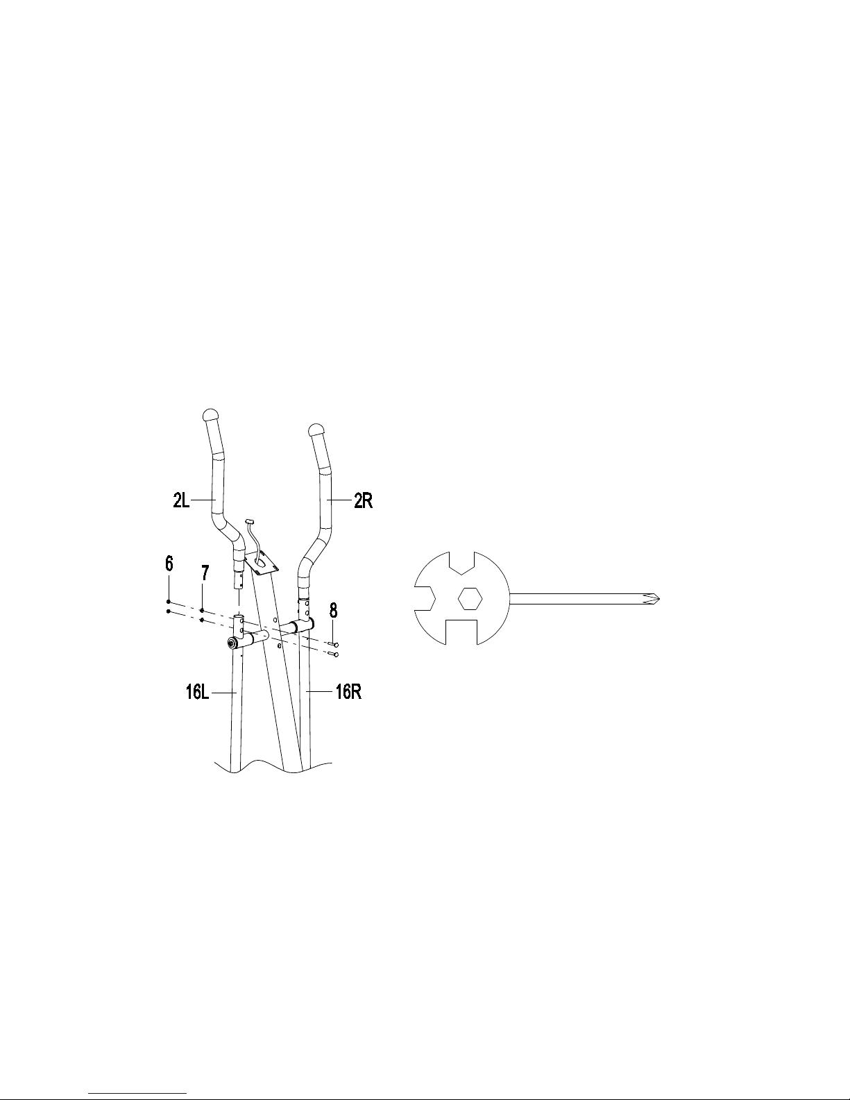
4. Left and Right Handrails Installation
Attach the Left/Right Handrails (2L, 2R) onto the Left/Right Handrail Arms (16L, 16R) with
four M6 Nylon Nuts (6), four Ø6xØ12x1 Curve Washers (7), and four M6x35 Carriage Bolts
(8). Tighten nylon nuts with the Multi Hex Tool with Phillips Screwdriver provided.
Hard are:
14
Tool:
Multi Hex Tool with Phillips Screwdriver
S10, S13, S14, S15

15
(6) Nylon Nut M6
4 PCS
(7) Curve Washer Ø6xØ12x1
4 PCS
(8) Carriage Bolt M6x35
4 PCS

5. Left and Right Handrail Arm Covers-A/B and Front/Rear Decorative Covers for
Front Post Installation
Remove two ST4.2x2 Screws (9) from the Left Handrail Arm (16L). Remove screws with
the Multi Hex Tool with Phillips Screwdriver provided.
Attach the Left Handrail Arm Cover-A (5) and Left Handrail Arm Cover-B (1 ) onto the Left
Handrail Arm (16L) with two ST4.2x2 Screws (9) and two ST4.2x12 Cross Recessed Pan
Head Tapping Screws (4). Tighten screws with the Multi Hex Tool with Phillips Screwdriver
provided.
Remove two ST4.2x2 Screws (9) from the Right Handrail Arm (16R). Remove screws
with the Multi Hex Tool with Phillips Screwdriver provided.
Attach the Right Handrail Arm Cover-A (5 ) and Right Handrail Arm Cover-B (51) onto the
Right Handrail Arm (16R) with two ST4.2x2 Screws (9) and two ST4.2x12 Cross Recessed
Pan Head Tapping Screws (4). Tighten screws with the Multi Hex Tool with Phillips
Screwdriver provided.
Attach the Front Decorative Cover for Front Post (41) and Rear Decorative Cover for Front
Post (42) onto the Front Post (47) two ST4.2x12 Cross Recessed Pan Head Tapping
Screws
(4). Tighten screws with the Multi Hex Tool with Phillips Screwdriver provided.
16
Tool:
Multi Hex Tool with Phillips Screwdriver
S10, S13, S14, S15

Hard are:
6. Handlebar and Computer Installation
Remove two M8x15 Hexagon Socket Pan Head Cap Bolts (33) and two Ø16xØ8x1.5 Curve
Washers (34) from the Front Post (47). Remove bolts with the S6 Allen Wrench provided.
Insert the Hand Pulse Sensor with Wires (32) through into the hole on the Front Post (47)
and pull them out from the top end of the Front Post (47).
Attach the Handlebar (37) onto the Front Post (47) with two M8x15 Hexagon Socket Pan
Head Cap Bolts (33) and two Ø16xØ8x1.5 Curve Washers (34) that were removed. Tighten
bolts with the S6 Allen Wrench provided.
Remove four M5x1 Cross Recessed Pan Head Bolts (4 ) from the back of the Computer
(38). Remove bolts with the Multi Hex Tool with Phillips Screwdriver provided.
Connect the Hand Pulse Sensor Wires (32) and Extension Sensor Wire (39) to the wires
that
come from the Computer (38). Tuck ires into the Front Post (47). Attach the Computer
(38) onto the top end of the Front Post (47) with f four M5x1 Cross Recessed
Pan Head Bolts (4 ) that were removed. Tighten bolts with the Multi Hex Tool with Phillips
17
(4) Cross Recessed Pan Head
Tapping Screw ST4.2x12
6 PCS
Allen Wrench S6
Tools:
Multi Hex Tool with Phillips Screwdriver
S10, S13, S14, S15

Screwdriver provided.
7. AC Adapter Installation
Plug one end of the AC Adapter (97) into the power jack of the Power Supply Wire (46) on
the rear of the Left Cover (63L). Before plugging in, make sure to check carefully
the specifications on the Adapter. Plug the other end of the AC Adapter (97) into the
electrical wall outlet.
18

OPERATING THE COMPUTER
COMPUTER BUTTON FUNCTIONS:
START/STOP: To start and stop the workout session.
19

UP: Press the UP button to select the exercise mode of MANUAL, PROGRAM, USER
PROGRAM, and H.R.C., and WATT PROGRAM.
Press the UP button to make upward for function values adjustment on different training
mode.
Press the UP button to increase the load level.
DOWN: Press the DOWN button to select the exercise mode of MANUAL, PROGRAM,
USER PROGRAM, and H.R.C., and WATT PROGRAM.
Press the DOWN button to make downward for function values adjustment on different
training mode.
Press the DOWN button to decrease the load level.
RECOVERY: The Pulse Recovery is for personal orientation and compares the
approximate pulse rate before and after training. You will notice that your fitness will
improve with regular exercise. This feature can help you on your way to a healthier you.
The Pulse Recovery feature is to be used directly after your workout. To use this function:
1) Grip the hand pulse sensors with both hands during exercise.
2) Press the RECOVERY button.
3) Grip the hand pulse sensors with both hands.
4) The time will countdown from 6 to seconds.
5) Your personal fitness Pulse Recovery level will appear on the display. When countdown
is complete, the Pulse Recovery grade will be displayed.
Your ratings for Pulse Recovery are as follo s:
F1 = Excellent F4 = Belo Average
F2 = Good F5 = Not Good
F3 = Fair F6 = Poor
6) Press the RECOVERY button to quit the recovery mode.
RESET: Press the RESET button to reset the functional values to zero
Press and hold the RESET button for over 2 seconds, the computer screen will display
initial
image (U1…, or U4).
MODE: To confirm your selection.
BODY FAT: To test your body fat percentage and BMI. Press the BODY FAT button and
then grip the hand pulse sensors with both hands for a few seconds, and the screen will
display your BMI, body fat percentage, and fat symbol.
20
Table of contents
Other Spartan Elliptical Trainer manuals


