Body Break 16117107 User manual
Elliptical
OWNER’S MANUAL
MODEL NO.
16117107
Assembly
Operation
Exercise
Parts
Warranty
CAUTION:
You must read and
understand this
owner’s manual
before operation
unit.
RETAIN FOR FUTURE REFERENCE
MAURICE PINCOFFS CANADA INC. 6050 DON MURIE STREET, NIAGARA FALLS, ONTARIO L2E 6X8

Customer Service 1-888-707-1880 Maurice Pincoffs Canada Inc.© 2010
2
Manufacture’s One-Year Limited Warranty
Your BODY BREAK Elliptical is warranted for one year from the date of purchase against
defects in material when used for the purpose intended, under normal conditions and
provided it receives proper care. Any part found defective or missing will be sent at no
cost when returned in accordance with the terms of this warranty.
This warranty is not transferable and is extended only to the original owner.
The warranty shall not apply to exercise units which are (1) used for commercial or other
income producing purposes, or (2) subject to misuse, neglect, accident or unauthorized
repair and alterations.
This warranty provided herein is lieu of all other express warranties, any implied
warranties, including any implied warranties of merchantability of fitness for particular
purpose, are limited in duration to the first 12 months from date of purchase. All other
obligations or liabilities, including liability for consequential damages are hereby
excluded.
REPAIR PARTS AND SERVICE
All of the parts for the elliptical shown in figure can be ordered from Maurice Pincoffs
Canada Inc. 6050 DON MURIE STREET, NIAGARA FALLS, ONTARIO L2E 6X8. When
ordering parts, the parts will be sent and billed at the current prices. Prices may be subject to
change without notice. Check or money order must accompany all orders. Standard
hardware items are available at your local hardware store.
To ensure prompt and correct handling of any errors, or to answer any questions, please call
our Toll Free number: 1-888-707-1880, or local number 1-905-353-8955 or fax 1-905-353-
8968, email customerservice@pincoffs.ca or visit us at www.pincoffs.ca. Office hours are
from 8:30 AM to 5:00 PM Monday to Friday Eastern Standard Time.
Always include the following information when ordering parts
Model number
Name of each part
Part number of each part
TABLE OF CONTENTS
WARRANTY 2 PARTS LIST 15-17
SAFETY PRECAUTIONS 3 EXPLODED VIEW 18
PRE-ASSEMBLY CHECK LIST 4 TROUBLE SHOOTING 19
HARDWARE PACKING LIST 5 TRAINING GUIDELINES 20-22
ASSEMBLY INSTRUCTION 6-10 EXERCISE ROUTINE 23-24
COMPUTER OPERATION 11-14

Customer Service 1-888-707-1880 Maurice Pincoffs Canada Inc.© 2010
3
SAFETY PRECAUTIONS
Thank you for purchasing our product. Even though we go to great efforts to ensure the quality
of each product we produce, occasional errors and/or omissions do occur. In any event should
you find this product to have either a defective or a missing part please contact us for a
replacement.
This product has been designed for home use only. Product liability and guarantee conditions
Will not be applicable to products being subjected to professional use or products being used in
a gym centre.
This exercise equipment was designed and built for optimum safety. However, certain precautions
apply whenever you operate a piece of exercise equipment. Be sure to read the entire manual
before assembly and operation of this machine. Also, please note the following safety
precautions:
1. Read the OWNER’S OPERATING MANUAL and all accompanying literature and
follow it carefully before using your elliptical.
2. If dizziness, nausea, chest pains, or any other abnormal symptoms are experienced
while using this equipment, STOP the workout at once. CONSULT A PHYSICIAN
IMMEDIATELY.
3. Inspect your exercise equipment prior to exercising to ensure that all nuts and bolts are
fully tightened before each use.
4. The elliptical must be regularly checked for signs of wear and damage. Any part found
defective, the part must be replaced with new spare part from the manufacturer.
5. Fitness equipment must always be installed on a flat surface, do not place the unit on a
loose rug or uneven surface. This will help prevent the unit from moving while it is being
used, which could possibly scratch or damage the surface of your floor.
6. No changes must be made which might compromise the safety of the equipment.
7. It is recommended to have a minimum of 1’ safe clearance around the exercise equipment
while in use.
8. Keep children and pets away from this equipment at all times while exercising.
9. Warm up 5 to 10 minutes before each workout and cool down 5 to 10 minutes afterward.
This allows your heart rate to gradually increase and decrease and will help prevent you
from straining muscles.
10. Never hold your breath while exercising. Breathing should remain at a normal rate in
conjunction with the level of exercise being performed
11. Always wear suitable clothing and footwear while exercising. Do not wear loose fitting
clothing that could become entangled with the moving parts of your elliptical.
12. Care must be taken when lifting or moving the equipment, so as not to injure your back.
Always use proper lifting techniques
13. User weight should not exceed 250 lbs.
14. Tie all long hair back and remove all personal jewelry before exercising.
15. After eating, allow 1-2 hours before exercising as this will help to prevent muscle
strain.
16. Injuries may result from incorrect or excessive training and using the equipment
otherwise than as directed or recommended by your doctor.
WARNING: Before beginning any exercise program consult your physician. This is
especially important for individuals over the age of 35 or persons with pre-
existing health problems. Read all instructions before using any fitness
equipment. We assume no responsibility form personal injury or property
damage sustained by or through the use of this product.

Customer Service 1-888-707-1880 Maurice Pincoffs Canada Inc.© 2010
4
PRE-ASSEMBLY CHECK LIST
PART
DESCRIPTION
Q’TY
35
Main frame
1
83
Front frame
1
3R / 3L
Upper handlebar
2
30
Front stabilizer w/ transportation wheels
1
60
Rear stabilizer w/leveling end caps
1
19
Upright
1
17R/L
Lower handlebar (Right / Left)
2
8
Stationary handlebar
1
4
Monitor
1
26R/L
Foot pedal (Right / Left)
2
46R/46L
Pedal tube (Right / Left)
2
Customer Service 1-888-707-1880 Maurice Pincoffs Canada Inc.© 2010
5
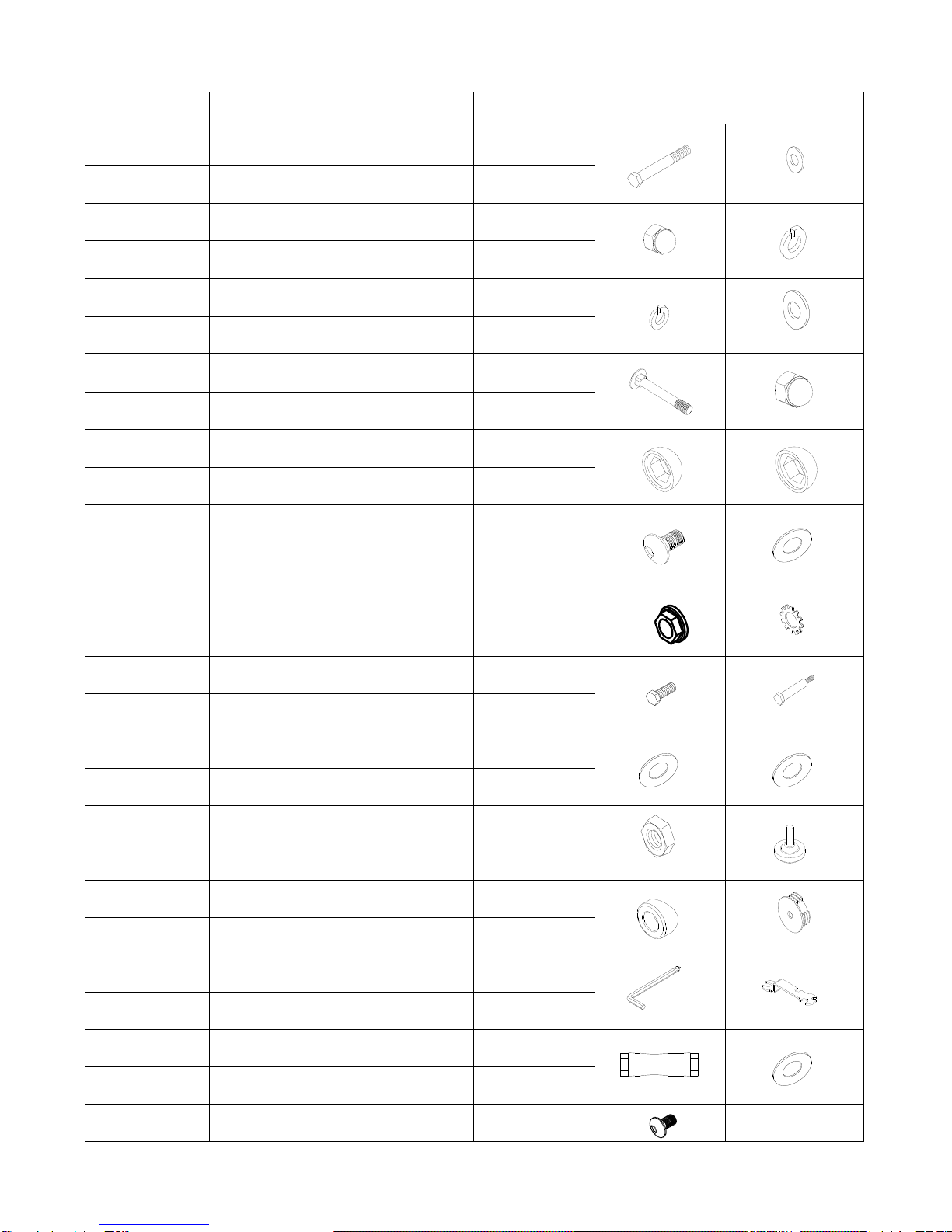
HARDWARE PACKING LIST
PARTS NO.
DESCRIPTION
Q’TY
SKETCH
5
Hex head bolt M6
4
6
Curve washer M6
4
7
Cap nut M6
4
13
Spring washer M8
16
76
Spring washer M6
4
21
Curve washer M8
12
31
Carriage bolt M8X75mm
4
32
Cap nut M8
4
74
Plastic cap M8
4
73
Plastic cap M10
4
12
Allen head bolt M8X20mm
8
15
Washer
2
67L/R
Lock nut M10
2
68
Tooth lock washer M10
2
75
Hex head bolt M8X15mm
2
25
Hex carriage bolt
2
44
Washer
2
24
Washer
2
23
Nylon nut M10
2
85
Wheel knob
1
18
Bushing
2
66
Plastic end cap
2
78
Allen wrench
1
79
Universal wrench
2
80
Universal wrench
1
14
Flat washer
2
90
Allen head bolt M8x25mm
2
Customer Service 1-888-707-1880 Maurice Pincoffs Canada Inc.© 2010
6
ASSEMBLY INSTRUCTION
This manual is designed to help you easily assemble, adjust and use this machine. Please read
this manual carefully. For the sake of familiarizing yourself with the parts identified in the instruction,
first study the overview drawing.
Set all parts in a clear area on the floor and remove the packing material. Refer to the parts list
for help to identify the parts. It will take two people to assemble your unit.
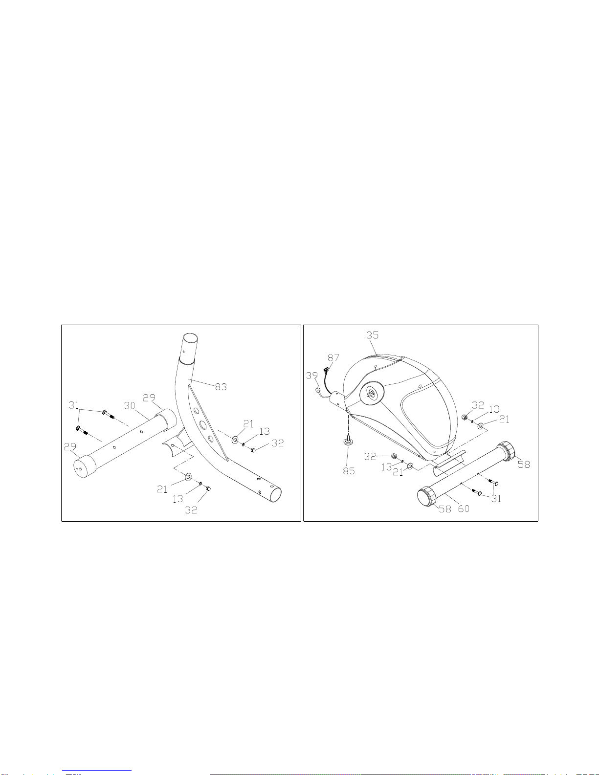
STEP 1
Attach the front stabilizer (30)with two transportation wheels (29) to front frame (83). Secure
using two carriage bolts (31), two curved washers (21), two spring washers (13) and two cap nuts
(32).
Attach the rear stabilizer (60) with two leveling end caps (58)to the main frame (35). Secure using
two carriage bolts (31), two curved washers (21), two spring washers (13)and two cap nuts (32).
Attach the levelling cap (85) to the bottom of front main frame (35).

Customer Service 1-888-707-1880 Maurice Pincoffs Canada Inc.© 2010
7
STEP 2
Slide the sensor wire (39) and the motor cable (87)up through the front frame (83).
Insert the front frame (83) in to the main frame (35) and secure with four allen head bolts (12), four
spring washers (13) and four curve washers (21).
Note: Please use the auxiliary cable (59) from the front frame to help you slide the wires up
through the front frame. Bind the wires to the auxiliary cable and pull the auxiliary cable out
of the front frame. Once you have the wires up through the front frame, discard the
auxiliary cable.
STEP 3
Connect the extension sensor wire (63) to sensor wire (39).
Connect the extension motor cable (22)to motor cable (87).
Insert the upright post (19) into the front frame (83) and secure with four allen head bolts (12), four
curve washers (21) and four spring washers (13).
Customer Service 1-888-707-1880 Maurice Pincoffs Canada Inc.© 2010
8
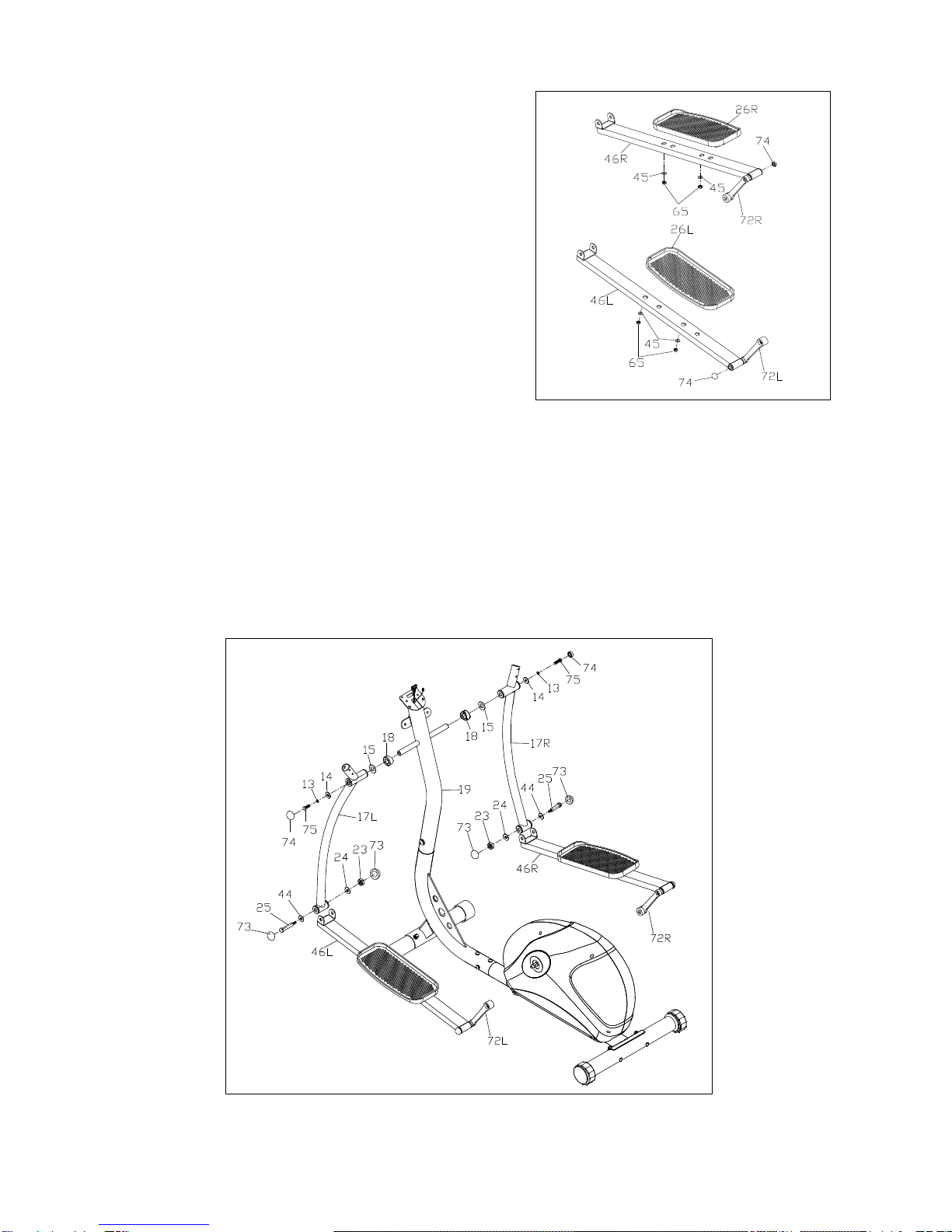
STEP 4
Remove two flat washers (45) and two nylon nuts (65)
from the left foot pedal (26L).
Attach the left pedal (26L) to the left pedal tube (46L)
in your desired position. Secure the pedal using
two flat washers (45) and two lock nuts (65)that you
have previously removed.
Repeat this procedure for the right pedal (26R).
STEP 5
Slide one curve sleeve (18) and one flat washer (15) onto the left side axle of the upright (19)
Attach the lower left handlebar (17L) on to the left side axle of the upright (19). Secure
with one flat washer (14), one spring washer (13), one allen head bolt (75) and one pvc cap (74).
Repeat for the right side (17R).
Attach the left lower handlebar (17L) to the “U”bracket of the left pedal tube (46L) and secure with
one allen head bolt (25), one flat washer (44), one flat washer (24), one nylon nut (23) and two
plastic caps (73).
Repeat this procedure for the right lower handlebar (17R).

Customer Service 1-888-707-1880 Maurice Pincoffs Canada Inc.© 2010
9
STEP 6
Attach the left crank arm (72L) from the left foot pedal (46L) and secure it to the axle of the pulley
(36) using one anti-washer (68), one left anti-nut (67L) and one axle cap (66).
Repeat this procedure for the right crank arm (72R).
Attach the two plastic caps (74) to the each crank arm (72L/R).
NOTE: The thread on the right of the pivot shaft (36) is right thread. Please use enclosed tools
(78/80)to tighten it clockwise. The thread on the left side of the pivot shaft (36) is left thread.
Please use attach enclosed tools (78/80)to tighten it counter-clockwise.
STEP 7
Attach the left upper handlebar (3L)to the left lower handlebar (17L) and secure with two hex
head bolts (5), two curve washers (6), two spring washers (76) and two cap nuts (7).
Repeat this procedure for the right upper handlebar (3R).

Customer Service 1-888-707-1880 Maurice Pincoffs Canada Inc.© 2010
10
STEP 8
Slide the hand pulse wire (10) from the stationary handlebar (8) around the rear of upright post
(19).
Attach the stationary handlebar (8) to the bracket of the upright post (19) and secure
with two spring washers (13) and two allen head bolts (90).
STEP 9
Remove the four screws (88) from the back of the monitor (4).
Connect the extension sensor wire (22) to the wire from the back of the monitor (4).
Connect the extension motor cable (63) to the cable from the back of the monitor (4).
Attach the monitor (4) to monitor bracket of upright post (19) and secure with the four screws (88)
which have been previously removed.
Connect the hand pulse wire (10) to the monitor (4).
.
YOUR UNIT IS NOW FULLY ASSEMBLED.
ENSURE THAT ALL NUTS AND BOLTS ARE FIRMLY TIGHTENED

Customer Service 1-888-707-1880 Maurice Pincoffs Canada Inc.© 2010
11
MONITOR OPERATION INSTRUCTIONS
BUTTONS:
▲(UP): Press to select programs P1 to P10.
Press to increase the values of the setting mode.
Press to increase the level of the workload when running a program.
▼(DOWN): Press to select programs P1 to P10.
Press to decrease the values of the setting mode.
Press to decrease the level of the workload when running a program.
ENTER: Press to confirm the selected programs P1 to P10.
Press the ENTER button to select the values of the various settings.
START/STOP: Press to start the selected program.
Press the START / STOP button to stop the program. You can press the
START / STOP button again to continue to run the current program, or use
“▲ / ▼ ” buttons to select a new program.
Press and hold for 4 seconds to reset all of the function values to zero.

Customer Service 1-888-707-1880 Maurice Pincoffs Canada Inc.© 2010
12
LCD DISPLAY INSTRUCTIONS
PROGRAM: Displays programs for selection during setup, from P1 to P10.
Displays the selected program during exercise.
TIME: Displays the time. Counts upward from one second to 99:59 minutes.
Counts down from preset value.
SPEED: Displays the current speed from zero 99.9 miles per hour.
DISTANCE: Displays the distance from zero to 999.9 miles.
CALORIE: Displays the calorie consumption from zero to 999.9 Kcal.
NOTE: The calories readouts is an estimate for an average user. It should be
Used only as a comparison between workouts on this unit.
HEART RATE: Displays heart rate in beats per minute from 40 to 240 beats per minute.
To display the heart rate, you must grasp the Pulse sensors on both sides of the
handrail, one in each hand. The heart symbol “♥” will begin flashing when the
computer senses your hear rate. Your heart rate will be displayed approximately
five (5) seconds after the heart icon is displayed. If you do not place your hands
correctly and 60 seconds passes without a heart rate reading, the computer will
turn off the heart rate circuit. If this occurs, press the START button to restart the
heart rate circuit, place your hands back on the Pulse Sensors correctly, and the
heart rate readout will appear.
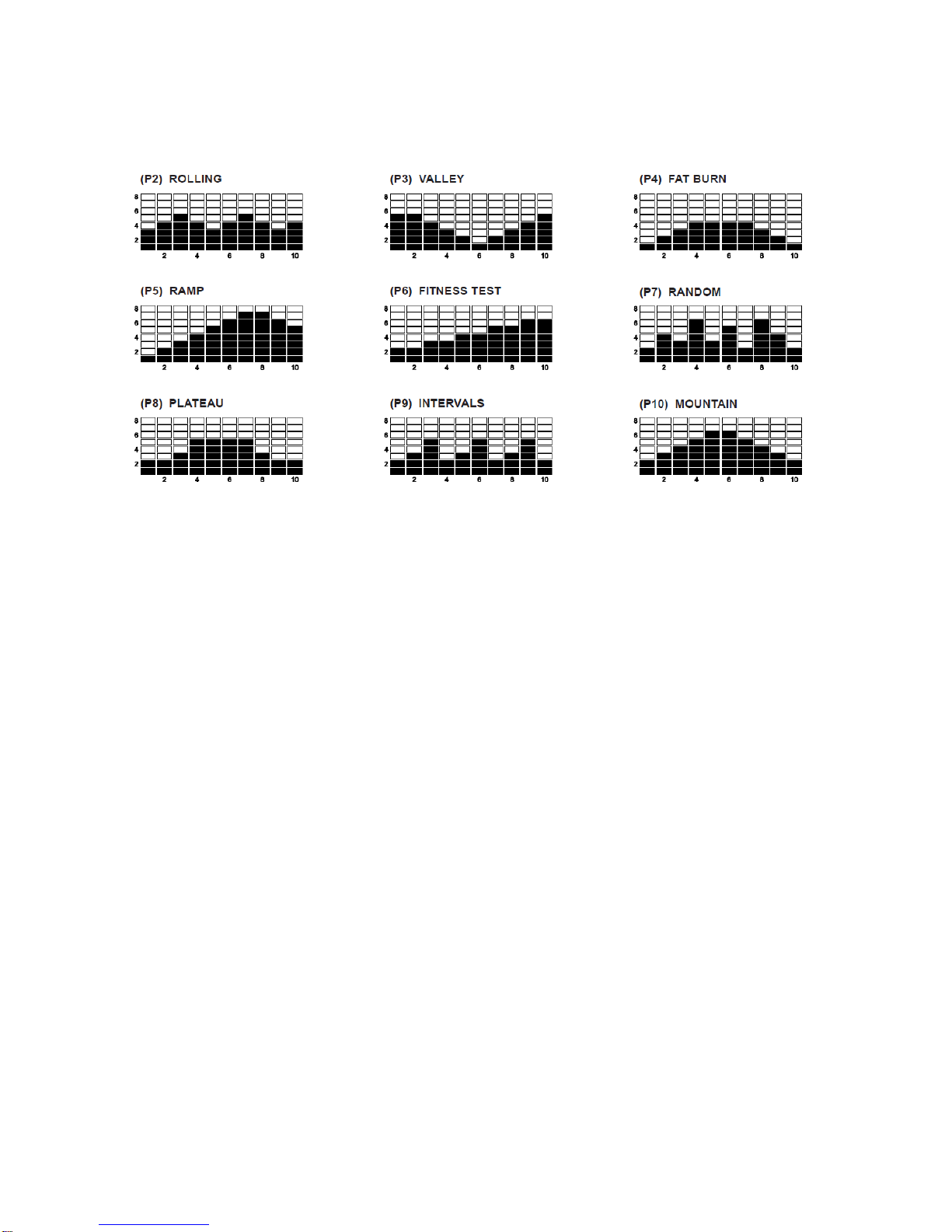
PROGRAM DESCRIPTIONS
his computer contains 10 different programs. You can preset the program time and the computer will
divide the time chosen into 10 intervals. If you do not set the programs time in advance, the
computer will default to a 30 minute workout time.
MANUAL PROGRAM:
P1 is a manual program allowing the user to full manual control of the
workload. Use the “▲” button to increase load. Use the “▼” button to
decrease the load.
Customer Service 1-888-707-1880 Maurice Pincoffs Canada Inc.© 2010
13
PRESET PROGRAMS: P2 to P10 are preset automatic programs. The profiles are shown on the
face of the computer. Use the “▲” button to increase the load level of the program. Use the “▼”
button to decrease the load level of the program.
COMPUTER OPERATION
STEP 1: POWER ON
Pedaling or press any button.
STEP 2: SELECT PROGRAM
Press the “▲ / ▼” buttons until the desired program is displayed.
STEP 3: SET THE PROGRAM TIME
Press the ENTER button, the TIME function mode will appear with the display flashing
“0:00”. Press the ENTER button again to pass setting the program time or use the “▲ /
▼” buttons to set the program time, from 5 minutes up to 99 minutes with 1 minute
increments. Press the ENTER button to confirm the setting. Press the START/STOP
button to start the program.
NOTE:
1. The program will not start until you press the START / STOP button
2. If you don’t set the program time, the computer will count up from one second up to
99:59 Minutes, and use the default workout time, 30 minutes, to run the program
profile.
3. The computer will count down from the program time that you set. When the timer
counts down to zero, the computer will alert you with an alarm that your workout
is complete. You can press any button to stop the alarm.

Customer Service 1-888-707-1880 Maurice Pincoffs Canada Inc.© 2010
14
OPERATION DESCRIPTIONS
1. Monitor requires four “AA” batteries.
2. To stop a running program, press the START / STOP button. In this mode, you can press the
START / STOP button again to continue to run the current program or,
you can use the “▲ / ▼” buttons to select a new program. The function values of DISTANCE
and CALORIE will continue to accumulate.
3. When you complete a program, press the START / STOP button to stop the program. You can
use the “▲ / ▼” buttons to select a new program. The function values of DISTANCE and
CALORIE will continue to accumulate. This will allow you to run several programs and still know
the total DISTANCE and CALORIE during the workout.
4. If you want to restart with a new program, press and hold the START button for four seconds to
reset all of the function values to zero. Use the “▲ / ▼” buttons to select a new program.
5. The computer will shut off automatically after 4 minutes of inactivity, and the function values,
DISTANCE and CALORIE, will be kept.

Customer Service 1-888-707-1880 Maurice Pincoffs Canada Inc.© 2010
15
PARTS LIST:
KEY NO.
PARTS NO.
DESCRIPITON
Q’TY
1
1710701
Handlebar end cap
2
2
1710702
Foam grip
2
3R
1710703R
Upper handlebar (Right)
1
3L
1710703L
Upper handlebar (Left)
1
4
1710704
Monitor
1
5
1710705
Hex head bolt M6
4
6
1710706
Curve washer M6
4
7
1710707
Cap nut M6
4
8
1710708
Stationary handlebar
1
9
1710709
Hand pulse sensor plate
2
10
1710710
Hand pulse wire
1
11
1710711
Cross head screw M4*15mm
2
12
1710712
Allen head bolt
8
13
1710713
Spring washer M8
18
14
1710714
Flat washer
2
15
1710715
Flat washer
2
16
1710716
Axle bushing
4
17R
1710717R
Lower handlebar (Right)
1
17L
1710717L
Lower handlebar (Left)
1
18
1710718
Bushing
2
19
1710719
Upright post
1
20
1710720
Motor w/cable
1
21
1710721
Curve washer
12
22
1710722
Extension motor cable
1
23
1710723
Nylon nut M10
3
24
1710724
Flat washer M10
2
25
1710725
Allen head bolt M10
2
26R
1710726R
Foot pedal (Right)
1
26L
1710726L
Foot Pedal (Left)
1
27R
1710727R
Chain cover (Right)
1
27L
1710727L
Crank cover (Left)
1
28
1710728
Pivot shaft cover
2

Customer Service 1-888-707-1880 Maurice Pincoffs Canada Inc.© 2010
16
29
1710729
Transportation wheel
2
30
1710730
Front stabilizer
1
31
1710731
Carriage bolt
4
32
1710732
Cap nut M8
4
33
1710733
Bushing
4
34
1710734
Drive belt
1
35
1710735
Main frame
1
36
1710736
Belt pulley w/pivot shaft
1
37
1710737
Magnet
1
38
1710738
Machine screw M5*15mm
1
39
1710739
Sensor with wire
1
40
1710740
Tension adjustor
2
41
1710741
Nut 3/8”*4mm
1
42
1710742
Nut 3/8”*7mm
2
43
1710743
Flat washer
2
44
1710744
Flat washer
2
45
1710745
Flat washer M6
4
46R
1710746R
Pedal tube (Right)
1
46L
1710746L
Pedal tube (Left)
1
47
1710747
Bushing
4
48
1710748
Flat washer
2
49
1710749
Magnetic flywheel system w/axle
1
50
1710750
Nylon nut M10*7mm
1
51
1710751
Allen head bolt M10*20mm
1
52
1710752
Idle wheel
1
53
1710753
Sleeve
1
54
1710754
Flat washer
2
55
1710755
Idler wheel bracket
1
56
1710756
Allen head bolt M10*40mm
1
57
1710757
Spring
1
58
1710758
Leveling end cap
2
59
1710759
Auxiliary cable
1
60
1710760
Rear stabilizer
1

Customer Service 1-888-707-1880 Maurice Pincoffs Canada Inc.© 2010
17
61
1710761
Machine screw M4*15mm
8
62
1710762
Round head screw M5*25mm
4
63
1710722
Extension sensor wire
1
64
1710764
Foam grip
1
65
1710765
Nylon nut M6
4
66
1710766
Crank arm cover
2
67R
1710767R
Flange nut (Right thread)
1
67L
1710767L
Flange nut (Left thread )
1
68
1710768
Anti - slippery washer
2
69
1710769
C ring
2
70
1710770
Adjustable washer
1
71
1710771
Bearing
2
72L
1710772L
Crank arm w/welded pedal axle (Left)
1
72R
1710772R
Crank arm w/welded pedal axle (Right)
1
73
1710773
Plastic cap M10
4
74
1710774
Plastic cap M8
4
75
1710775
Hex head bolt M8*20mm
4
76
1710776
Spring washer M6
4
77
1710777
Hand pulse wire protector
2
78
1710778
Allen wrench
1
79
1710779
Universal wrench
2
80
1710780
Universal wrench
1
81
1710781
Resistant cable
1
82
1710782
Square end cap
2
83
1710783
Front frame
1
84
1710784
Nut 3/8”*9mm
1
85
1710785
Leveling Knob
1
86
1710786
Clip
2
87
1710787
Extension motor cable
1
88
1710788
Screw M5X15mm
4
89
1710789
Foam
2
90
1710790
Allen head bolt M8x25mm
2
Customer Service 1-888-707-1880 Maurice Pincoffs Canada Inc.© 2010
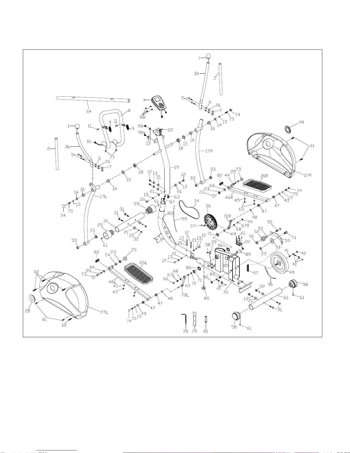
18
DIAGRAM

Customer Service 1-888-707-1880 Maurice Pincoffs Canada Inc.© 2010
19
TROUBLE SHOOTING GUIDE
Problem
Cause
Correction
Monitor does not display
Batteries not installed
Insert batteries
No speed or distance
displays on the monitor
Sending unit not connected
Securely plug sending unit into
extension wire and the back of
the computer
Sending unit not working
properly
Replace sending unit
Computer not working properly
Replace computer
No tension
Motor cable or resistant cable
not connected
Securely connect the motor
cable into the extension motor
cable and the resistant cable
Magnetic wheel not working
properly
Replace magnetic wheel
Heart rate not displaying
Pulse wire not connected not
connected
Securely plug wires together
Hand pulse defective
Replace hand pulse
Computer not working properly
Replace computer
Grinding
Crank bearing defective
Replace crank bearings
Idler pulley defective
Replace idler pulley
Mag. flywheel defective
Replace mag. flywheel
Squealing
Poly V-belt slipping
Adjust poly v-belt

Customer Service 1-888-707-1880 Maurice Pincoffs Canada Inc.© 2010
20
TRAINING GUIDELINES
Exercise
Exercise is one of the most important factors in the overall health of an individual. Listed among its
benefits are:
Increased capacity for physical work (strength endurance)
Increased cardiovascular (heart and arteries/veins) and respiratory efficiency
Decreased risk of coronary heart disease
Changes in body metabolism, e.g. losing weight
Delaying the physiological effects of age
Physiological effects, e.g. reduction in stress, increase in self-confidence, etc.
Basic Components of Physical Fitness
There are four all encompassing components of physical fitness and we need to briefly define each
and clarify its role.
Strength is the capacity of a muscle to exert a force against resistance. Strength contributes to
power and speed and is of great importance to a majority of sports people.
Muscular Endurance is the capacity to exert a force repeatedly over a period of time, e.g. it is
the capacity of your legs to carry you 10 Km without stopping.
Flexibility is the range of motion about a joint. Improving flexibility involves the stretching of
muscles and tendons to maintain or increase suppleness, and provides increased resistance to
muscle injury or soreness.
Cardio-Respiratory Endurance is the most essential component of physical fitness. It is the efficient
functioning of the heart and lungs
Aerobic Fitness
The largest amount of oxygen that you can use per minute during exercise is called your maximum
oxygen uptake (MVo2). This is often referred to as your aerobic capacity.
The effort that you can exert over a prolonged period of time is limited by your ability to deliver
oxygen to the working muscles. Regular vigorous exercise produces a training effect that can
increase your aerobic capacity by as much as 20 to 30%. An increased MVO2 indicates an
increased ability of the heart to pump blood, of the lungs to ventilate oxygen and of the muscles to
take up oxygen.
Anaerobic Training
This means “without oxygen” and is the output of energy when the oxygen supply is insufficient to
meet the body’s long term energy demands. (For example, 100 meter sprint).
The Training Threshold
This is the minimum level of exercise which is required to produce significant improvements in any
physical fitness parameter.
Progression
As your become fitter, a higher intensity of exercise is required to create an overload and therefore
provide continued improvement
Overload
This is where you exercise at a level above that which can be carried out comfortably. The intensity,
duration and frequency of exercise should be above the training threshold and should be gradually
increased as the body adapts to the increasing demands. As your fitness level improves, so the
training threshold should be raised. Working through your program and gradually increasing the
overload factor is important.
Table of contents
Other Body Break Elliptical Trainer manuals


Popular Elliptical Trainer manuals by other brands


Sunny Health & Fitness
Sunny Health & Fitness Endurance Zone SF-E3804 user manual
ICON Health & Fitness
ICON Health & Fitness NordicTrack Commercial 12.9 user manual

Weslo
Weslo Momentum 220X WLEL2006.0 user manual

NordicTrack
NordicTrack E 11.6 Elliptical Bedienungsanleitung

Ivation
Ivation Wooden Balance Board user guide

Kettler
Kettler Cross P instruction manual

NordicTrack
NordicTrack CXT 910 Manuel de l'utilisateur

Finnlo
Finnlo maximum Series Training manual

Garmin
Garmin Forerunner 310XT - Running GPS Receiver Declaration of conformity

URBANIX
URBANIX Proludic R37-UBX-224B Assembly guidelines

Gold's Gym
Gold's Gym GGEL60407.1 user manual

Domyos
Domyos VE 200 user manual