Spartan 1331 User manual

CROSSTRAINER BASIC+ ITEM NO: 1331

OWNER’S MANUAL
IMPORTANT: Read all instructions carefully before using this product. Retain this
owner’s anual for future reference.
The specifications of this product ay vary fro this photo, subject to change without
notice.
IMPORTANT SAFETY INSTRUCTIONS ------------------------------------------- 2
PARTS LIST ------------------------------------------------------------------------------- 3
HARDWARE PACKING LIST --------------------------------------------------------- 5
TOOLS -------------------------------------------------------------------------------------- 6
OVERVIEW DRAWING ----------------------------------------------------------------- 7
ASSEMBLY INSTRUCTIONS --------------------------------------------------------- 8
OPERATING THE COMPUTER ------------------------------------------------------ 15
AD USTMENTS -------------------------------------------------------------------------- 16
MAINTENANCE -------------------------------------------------------------------------- 17
TROUBLESHOOTING ------------------------------------------------------------------ 17
WARM UP AND COOL DOWN ROUTINE ----------------------------------------- 18
IMPORTANT SAFETY INSTRUCTIONS
Basic precautions should alwa s be followed, including the following important
safet instructions when using this equipment: Read all instructions before using
this

equipment.
1. Read all instructions and follow it carefully before using this equipment. Make sure the
equipment is properly assembled and tightened before use.
2. Before exercise, in order to avoid injuring the muscle, warm-up exercise is necessary.
Refer to the Warm Up and Cool Down Routine pages. After exercise, relaxation of the
body is suggested for cool-down.
3. Please make sure all parts are not damaged and fixed well before use. This equipment
should be placed on a flat surface when using. Using a mat or other covering material
on the ground is recommended.
4. Please wear proper clothes and shoes when using this equipment; do not wear clothes
that might catch any part of the equipment.
5. Do not attempt any maintenance or adjustments other than those described in this
manual. Should any problems arise, discontinue use and consult your local dealer.
6. Be careful when step on or leave the pedal always hold the handlebars first. Make the
pedal at your side at the lowest position, step on the pedal, and stride over the main
frame then step on the other pedal. When using, please hold the handlebar by hands,
make the pedals running smoothly by push or pull handlebars, then run the equipment
regularly by cooperation of hands and feet. After exercise, please also make one
pedal at the lowest position and leave your foot on the higher pedal first and then
another.
7. Do not use the equipment outdoors.
8. This equipment is for household use only.
9. Only one person at a time should use this equipment.
10. If you feel any chest pains, nausea, dizziness, or short of breath, you should stop
exercising immediately and consult your physician before continuing.
11. Care should be taken in mounting or dismounting the equipment.
12. Do not allow children to use or play on the equipment. Keep children and pets away
from the equipment while in use. This machine is designed for adults use only. The
minimum free space required for safe operation is not less than two meters.
13. The maximum weight capacity for this product is 250 LBS/110 kgs.
WARNING: Before beginning an exercise program consult our

ph sician. This is especiall important for the persons who are over 35 ears old or
who have pre-existing health problems. Read all instructions before using an
fitness equipment.
CAUTION: Read all instructions carefull before operating this product.
Retain this Owner’s Manual for future reference.
PARTS LIST
No. Description Qt No. Description Qt
001 Main Frame Ø50x2
hlavní rám
hlavný rám
1 027 Nylon Nut M6
nylonová matice
nylonová matica
8
002L Left Foot Bar 40x25x1.5
levý stupátko
lavé stúpátko
1 028 Washer Ø6
podložka
7
002R Right Foot Bar 40x25x1.5
pravé stúpátko
1 029 Bolt M6x40
šroub
skrutka
6
003L Left Handrail Arm Ø32x1.5
levá paže zábradlí
lavá paža zábradlia
1 030 Tension Cable L=1600
kabel napětí
kábel napätia
1
003R Right Handrail Arm Ø32x1.5
pravá paže zábradlí
pravá paža zábradlia
1 031 Bolt Cap S13
zakončení šroubu
2
004L Left Handrail Ø32x1.5
levé zábradlí
1 032 Screw ST4.2x25
šroub
skrutka
7
004R Right Handrail Ø32x1.5
pravé zábradlí
1 033L Foot Bar Cover-A 2
005 Front Post Ø50x1.5 1 033R Foot Bar Cover-B 2
006 Handlebar Ø28x1.5
řidítká
riadidlá
1 034 Big Washer Ø20xØ8x2
velká podložka
2
007 Bolt M6x10
šroub
1 035 Bolt Ø15.8x62.5
šroub
2

skrutka skrutka
008 Screw ST2.9x10
šroub
skrutka
2 036 Left Foot Pedal 395x150x65 1
009 Hexagon Head Bolt M8x30
šestihranní šroub
1 037 Right Foot Pedal 395x150x65 1
010 Front Stabilizer Ø50x1.5x480
přední stabilizátor
predný stabilizátor
1 038 Front Stabilizer End Cap Ø50
predné zakončenie stabilizátora
2
011 Rear Stabilizer Ø50x1.5x480
zadní stabilizátor
zadný stabilizátor
1 039 Bolt M6x48
šroub
skrutka
2
012 Bolt M10x57
šroub
skrutka
4 040 Transport Wheel Ø23xØ6x32
transportní kolo
transportné kolo
2
013 Rear Stabilizer End Cap
Ø50x1.5
2 041 Bolt M8x16
šroub
skrutka
8
014 Big Curve Washer Ø10
velká kulatá podložka
velká gulatá podložka
4 042 Curve Washer Ø20xØ8
kulatá podložka
gulatá podložka
6
015 Cap Nut M10 4 043 Bolt M10x18
šroub
skrutka
2
016L Bolt for left U Shape Bracket
Ø16x88.5xL23
1 044 Spring Washer Ø18xØ10x2
napínací podložka
napínacia podložka
2
016R Bolt for right U Shape Bracket
Ø16x88.5xL23
1 045 Washer Ø28x5
podložka
2
017L Left Nylon Nut 1/2” 1 046 Powder Metal Bushing
Ø33xØ29xØ16x14x4
4
017R Right Nylon Nut 1/2” 1 047 Bolt M6x35 4
018 Wave Washer Ø28xØ17x0.3
vlněná podložka
2 048 Curve Washer Ø6 4
019 Powder Metal Bushing
Ø29xØ16x14
8 049 Bolt Cap S16 2
020 Spring Washer Ø12
napínací podložka
napínacia podložka
2 050 Cap Nut M6 4
021 Bearing 6000 2Z
ložisko
2 051 Plastic Bushing Ø32xØ16x5xØ50 2
022 Washer Ø40xØ24xδ2.5 1 052L Left Handrail Arm Cover-A 1
023 U Shape Bracket 2 052R Right Handrail Arm Cover-A 1
024 Nylon Nut M8
nylonová matice
nylonová matica
2 053L Left Handrail Arm Cover-B 1
025 Washer Ø16xØ8x1.5 2 053R Right Handrail Arm Cover-B 1

podložka
026 Bolt M8x50
šroub
skrutka
2 054 Tension Control Knob 0325-
BC62003-0101
knoflík napětí
1
PARTS LIST
No. Description Qt No. Description Qt
055 Screw ST2.9x12
šroub
skrutka
8 075 Bearing Nut II 7/8”
ložisková matica
1
056 Computer VT 29104
počítač
1 076 Washer Ø34.5xØ23x2.5
podložka
1
057 Bolt M5x12
šroub
skrutka
4 077 Hexagon Nut 7/8”
šestihranná matica
1
058 Hand Pulse Sensor with Wire
L=750
2078 Belt Pulley with Crank Ø240 1
059 Handrail Foam Grip
Ø31xØ37x480
2079 Powder Metal Bushing Ø18xØ8x5 4
060 Spring Washer Ø8
napínací podložka
6 080 Nut for Flywheel M10x1.25 2
061 Handrail End Cap Ø32x1.5 2 081 Flywheel Ø230x40x32 1
062 Handlebar End Cap Ø28x1.5 2 082 Belt P 330 6 1
063 Screw ST4.2x20 2 083 Idle Wheel Bracket 1
064 Curve Washer for Tension
Control Knob Ø20xØ5.2
1084 Bolt M8x20
šroub
skrutka
2
065 Bolt for Tension Control Knob
M5x25
1085 Eyebolt M6x36 2
066 Phillips Self Tapping Screw
ST4.2x25
4086 Tension Bracket 31x31xδ1.0 2
067 Sensor Wire I L=1100
senzorový drát
1 087 Spring Washer Ø6
napínací podložka
2
068 Sensor Wire II L=950
senzorový drát
1 088 Hexagon Nut M6
šestihranná matice
2
069 Screw ST4.2x20
šroub
skrutka
4089 Bolt M8x10
šroub
skrutka
1
070 Left Cover 544x345x86
levý kryt
1090 Handlebar Foam Grip
Ø33xØ27x360
2
071 Right Cover 544x345x84
pravý kryt
1 091 Cover Cap Ø40xØ25x10 2
072 Bearing Cup Ø51.5
ložisková
2092 Big Washer Ø20xØ10x2
velká podložka
2
073 Bearing 2 093 Curve Washer Ø16xØ8x1.5 2
ložisko kulatá podložka
074 Bearing Nut I 15/16”
ložisková matica
1 094 Washer Ø10.2xØ14xδ1.0
podložka
2
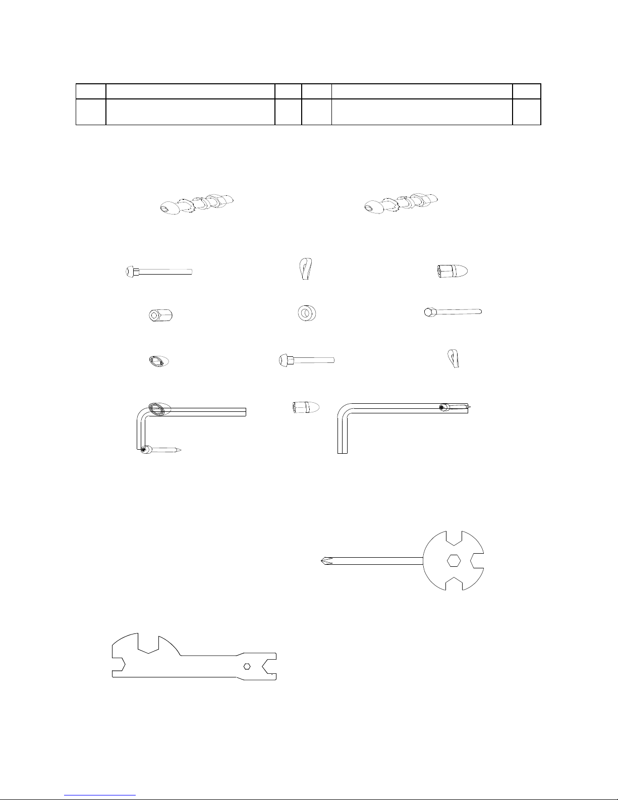
HARDWARE PACKING LIST
TOOLS
Multi Hex Tool
S10, S13, S17, S19
1 PC
Allen Wrench S6
1 PC
Allen Wrench S8
1 PC
Multi Hex Tool with Phillips Screwdriver
S10, S13, S14, S15
1 PC
(12) Bolt M10x57
4 PCS
(15) Cap Nut M10
4 PCS
(16R) Bolt for right U Shape
Bracket Ø16x88.5xL23 1
PC
(17R) Right Nylon Nut 1/2” 1
PC
(18) Wave Washer
Ø28xØ17x0.3
1 PC
(20) Spring Washer Ø12 1
PC
(16L) Bolt for left U Shape
Bracket Ø16x88.5xL23 1
PC
(17L) Left Nylon Nut 1/2” 1 PC
(18) Wave Washer
Ø28xØ17x0.3
1 PC
(20) Spring Washer Ø12 1
PC
(27) Nylon Nut M6
6 PCS
(28) Washer Ø6
6 PCS
(29) Bolt
M6x40
6 PCS
(31) Bolt Cap
S13
2 PCS
(14) Big Curve Washer
Ø10
4 PCS
(47) Bolt
M6x35
4 PCS
(48) Curve Washer
Ø6
4 PCS
(55) Screw ST2.9x12
8 PCS
(69) Screw ST4.2x20
4 PCS
(49) Bolt Cap S16
2 PCS
(50) Cap Nut M6
4 PCS

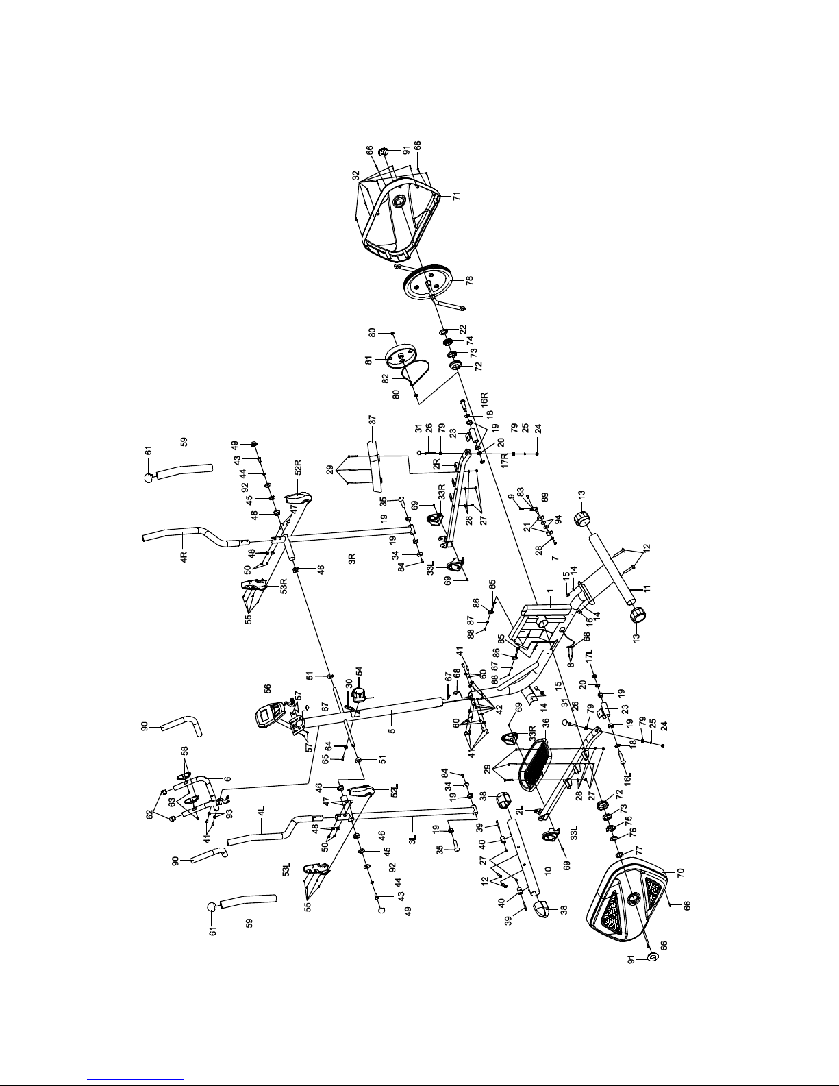
OVERVIEW DRAWING

ASSEMBLY INSTRUCTIONS
1. Front and Rear Stabilizers Installation
Position the Front Stabilizer (10) in front of Main Frame (1) and align bolt holes.
Attach the Front Stabilizer (10) onto the front curve of the Main Frame (1) with two M10x57
Bolts (12), two Ø10 Big Curve Washers (14), and two M10 Cap Nuts (15). Tighten cap nuts
with the Multi Hex Tool provided.
Position the Rear Stabilizer (11) behind the Main Frame (1) and align bolt holes.
Attach the Rear Stabilizer (11) onto the rear curve of the Main Frame (1) with two M10x57
Bolts (12), two Ø10 Big Curve Washers (14), and two M10 Cap Nuts (15). Tighten cap nuts
with the Multi Hex Tool provided.
Hardware:
Multi Hex Tool
S10, S13, S17, S19
Tool:
(12) Bolt M10x57
4 PCS
(15) Cap Nut M10
4 PCS
(14) Big Curve Washer
Ø10
4 PCS

2. Front Post and Tension Control Knob Installation
Remove six M8x16 Bolts (41), six Ø8 Spring Washers (60), and six Ø20xØ8 Curve
Washers (42) from the Main Frame (1). Remove bolts with the S6 Allen Wrench provided.
Insert the Tension Cable (30) through into the bottom hole of Front Post (5) and pull it out
from the square hole of Front Post (5).
Connect the Sensor Wire II (68) from the Main Frame (1) to the Sensor Wire I (67) from the
Front Post (5).
Insert the Front Post (5) onto the tube of the Main Frame (1) and secure with six M8x16
Bolts (41), six Ø8 Spring Washers (60), and six Ø20xØ8 Curve Washers (42) that were
removed. Tighten bolts with the S6 Allen Wrench provided.
Remove the Ø20xØ5.2 Curve Washer for Tension Control Knob (64) and M5x25 Bolt for
Tension Control Knob (65) from the Tension Control Knob (54). Remove bolt with the Multi
Hex Tool with Phillips Screwdriver provided.
Put the cable end of resistance cable of Tension Control Knob (54) into the spring hook of
Tension Cable (30), see Figure A. Pull the resistance cable of Tension Control Knob (54)
up and force it into the gap of metal bracket of Tension Cable (30), see Figure B. Attach
the Tension Control Knob (54) onto the Front Post (5) with the Ø20xØ5.2 Curve Washer for
Tension Control Knob (64) and M5x25 Bolt for Tension Control Knob (65) that were
removed. Tighten bolt with the Multi Hex Tool with Phillips Screwdriver provided.
2 .

3. Left/Right Handrail Arms, Left/Right Foot Bars, Left/Right Foot Pedals, and Foot
Bar Covers-A/B Installation
Remove two M10x18 Bolts (43), two Ø18xØ10x2 Spring Washers (44), two Ø20xØ10x2
Big
Washers (92), and two Ø28x5 Washers (45) from the left and right horizontal axes of the
Front Post (5). Remove bolts with the Multi Hex Tool provided.
Attach the Left Handrail Arm (3L) onto the left horizontal axis of the Front Post (5) with one
M10x18 Bolt (43), one Ø18xØ10x2 Spring Washer (44), one Ø20xØ10x2 Big Washer (92),
and one Ø28x5 Washer (45) that were removed. Tighten bolts with the Multi Hex Tool
provided. Install a S16 Bolt Cap (49) onto the M10x18 Bolt (43).
Attach the left U Shape Bracket (23) to the left Crank (78) with one Ø16x88.5xL23 Bolt for
left U Shape Bracket (16L), one Ø28xØ17x0.3 Wave Washer (18), Ø12 Spring Washer
(20),
and 1/2” Left Nylon Nut (17L). Tighten bolt and nylon nut with the S8 Allen Wrench and
Multi Hex Tool
S10, S13, S17, S19
Allen Wrench S8
Multi Hex Tool with Phillips Screwdriver
S10, S13, S1 , S15
Tool:

Multi Hex Tool provided. Install a S13 Bolt Cap (31) onto the M8x50 Bolt (26).
NOTE: Ø16x88.5xL23 Bolt for left U Shape Bracket (16L) and Ø16x88.5xL23 Bolt for
right U Shape Bracket (16R) are marked “R” for Right and “L” for Left.
Attach the Left Foot Pedal (36) onto the Left Foot Bar (2L) with three M6 Nylon Nuts (27),
three Ø6 Washers (28), and three M6x40 Bolts (29). Tighten nylon nuts with the Multi Hex
Tool with Phillips Screwdriver provided.
Attach the Foot Bar Covers-A/B (33L, 33R) onto the Left Foot Bar (2L) with two ST4.2x20
Screws (69). Tighten screws with the Multi Hex Tool with Phillips Screwdriver provided.
Repeat above step to attach the Right Handrail Arm (3R) onto the right horizontal axis of
the
Front Post (5) and right U Shape Bracket (23) to the right Crank (78).
3:
Hardware:
4. Left and Right Handrails Installation
Attach the Left/Right Handrails (4L, 4R) onto the Left/Right Handrail Arms (3L, 3R) with four
M6x35 Bolts (47), four Ø6 Curve Washers (48), and four M6 Cap Nuts (50). Tighten cap
nuts with the Multi Hex Tool with Phillips Screwdriver provided.
Hardware:
(47) Bolt
M6x35
4 PCS
(48) Curve Washer Ø6
4 PCS
(50) Cap Nut M6
4 PCS
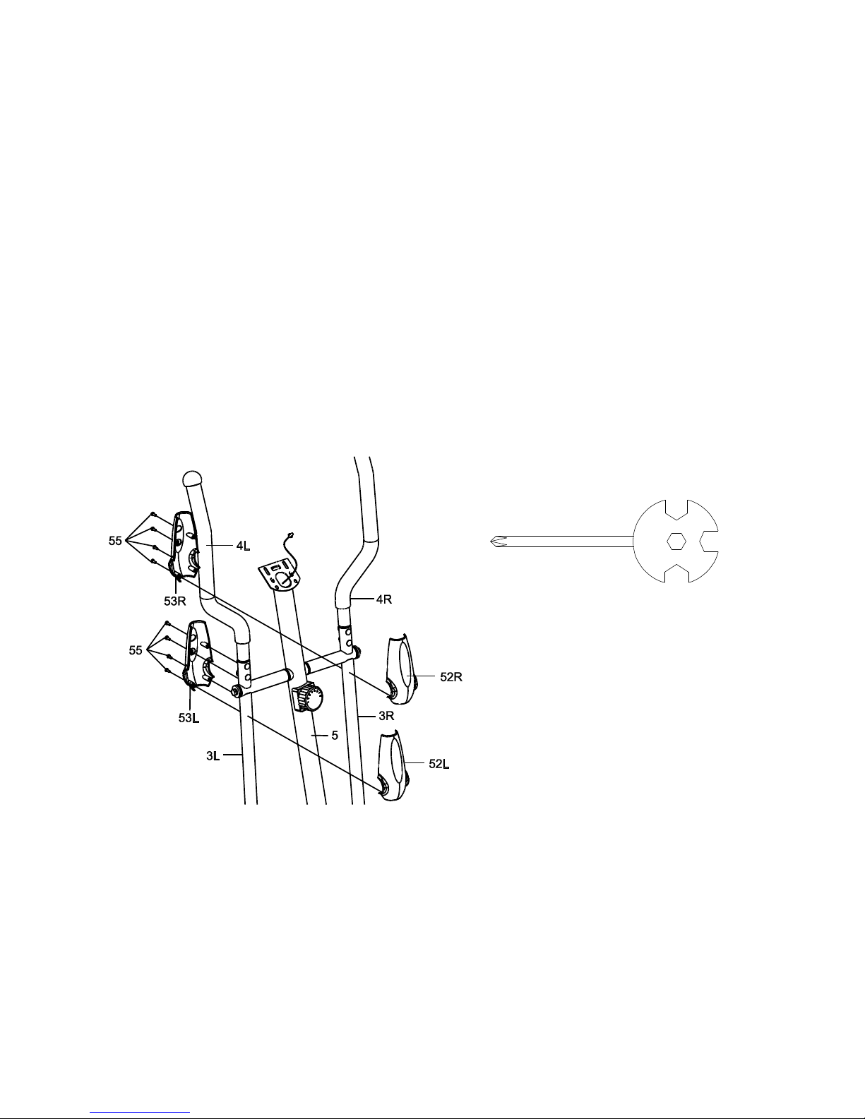
5. Left and Right Handrail Arm Covers-A and B Installation
Attach the Left Handrail Arm Cover-A (52L) and Left Handrail Arm Cover-B (53L) onto the
Left Handrail Arm (3L) with four ST2.9x12 Screws (55). Tighten screws with the Multi Hex
Tool with Phillips Screwdriver provided.
Attach the Right Handrail Arm Cover-A (52R) and Right Handrail Arm Cover-B (53R) onto
The Right Handrail Arm (3R) with four ST2.9x12 Screws (55). Tighten screws with the Multi
Multi Hex Tool with Phillips Screwdriver
S10, S13, S1 , S15
Tool:

Hex Tool with Phillips Screwdriver provided.
5 .
Hardware:
(55) Screw ST2.9x12
8 PCS

6. Handlebar and Computer Installation
Remove four M5x12 Bolts (57) from the back of the Computer (56). Remove bolts with the
Multi Hex Tool with Phillips Screwdriver provided.
Remove two M8x16 Bolts (41) and two Ø16xØ8x1.5 Curve Washers (93) from the Front
Post (5). Remove bolts with the S6 Allen Wrench provided.
Insert the Hand Pulse Sensor Wires (58) from the Handlebar (6) into the hole on the Front
Post (5) and then pull them out from the top end of the Front Post (5).
Attach the Handlebar (6) onto the Front Post (5) with two M8x16 Bolts (41) and two
Ø16xØ8x1.5 Curve Washers (93) that were removed. Tighten bolts with the S6 Allen
Wrench provided.
Connect the Sensor Wire I (67) and Hand Pulse Sensor Wires (58) to the wires that come
from the Computer (56) and then attach the Computer (56) onto the top end of the Front
Post (5) with four M5x12 Bolts (57) that were removed. Tighten bolts with the Multi Hex
Tool with Phillips Screwdriver provided.
6 .
OPERATING THE COMPUTER
Allen Wrench S6
Multi Hex Tool with Phillips Screwdriver
S10, S13, S1 , S15
Tool:

USING YOUR COMPUTER
The computer can be activated by pressing the buttons or by
pedaling. If you leave the equipment for 4 minutes, the power will
turn off automatically.
BUTTON FUNCTIONS:
MODE: Press the MODE button to select each function of the
computer.
Press and hold the MODE button for 4 seconds to reset all data values to zero except the
ODO (ODOMETER) data values.
Funkce tlačítek:
COMPUTER FUNTIONS:
SCAN: Press the MODE button until the arrow points to SCAN, the computer will
automatically scans each function in sequence with change every 5 seconds.
NOTE: If you do not want to use the SCAN function, press the MODE button to select one
of
the other functions.
TIME: Press the MODE button until the arrow points to TIME, the computer will display your
elapsed workout time in minutes and seconds.
SPEED: Press the MODE button until the arrow points to SPEED, the computer will display
the current training speed.
CAL (CALORIES): Press the MODE button until the arrow points to CAL, the computer will
display the total accumulated calories burned during workout.
PULSE: Press the MODE button until the arrow points to PULSE and then hold both two
hands on handlebar grip sensors, the screen will display your current heart rate figures and
a heart symbol. To ensure the pulse readout is more precise, please always hold on to the
handlebar grip sensors with two hands instead of just with one hand only when you try to
test your heart rate figures.
DIST (DISTANCE): Press the MODE button until the
arrow points to DIST, the computer will display the
accumulative distance traveled during workout.
ODO (ODOMETER): Press the MODE button until the
arrow points to ODO, the computer
will display the total accumulative distance.
ODO(ODOMETER):
Zobrazuje prejditú vzdialenost. Dátové hodnoty zobrazuje
ODO stisknutím a pridržaním tlačidla MODE alebo RESET po
dobu 3 sekundy. Pokial máte dobrú batériu v počítači, budu
ODO dáta jasné.
HOW TO INSTALL THE BATTERIES:
1. Remove the battery cover on the back of the
computer.
2. Place one "SIZE-AAA" batteries into the battery
housing.
3. Insure batteries are correctly positioned and
battery springs are proper contact with
batteries.
4. Re-install the battery cover.
5. If the display is illegible or only partial segment
appear, remove batteries and wait 15 seconds
before reinstalling.
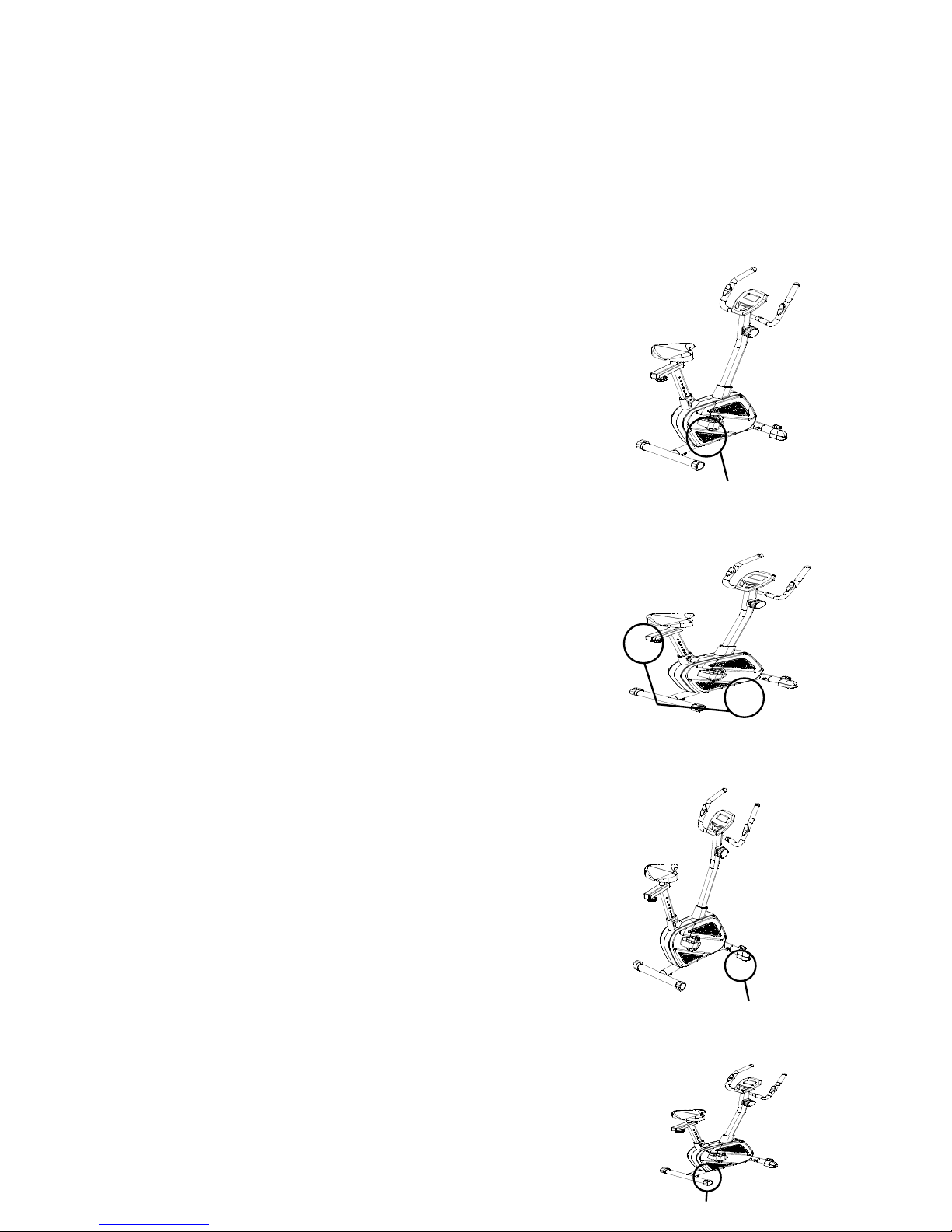
Tension Control Knob
Rear Stabilizer End Cap
Seat Post Knob
Seat Adjustment Knob

Adjusting the Tension Control Knob
To increase the load, turn the tension control knob in a
clockwise direction.
To decrease the load, turn the tension control knob in a
counterclockwise direction.
Adjusting the Handlebar
Hold the handlebar while loosening the handlebar T-Knob.
Adjust the handlebar to the desired position and turn the
handlebar T-Knob in a clockwise direction to tighten.
NOTE: Continue to turn the handlebar T-Knob until
handlebar is secure before exercising.
Adjusting the Adjustable Leveler
Turn the adjustable leveler on the rear stabilizer as needed
to level the upright bike.
Adjusting the Seat Height
Turn the seat post knob in a counterclockwise direction
until it can be pulled out. Pull out the seat post knob and
then slide the seat post up or down direction to the suitable
position. Lock the seat post in place by releasing the seat
post knob and sliding the seat post up or down slightly until
the seat post knob "pops" down into the locked position.
For added safety, tighten the seat post knob in a clockwise
direction.
NOTE: When adjusting the height of seat post, make
sure the seat post bushing does not exceed the mark
line on the seat post.
Adjusting the Seat Forward or Back
Turn the seat adjustment knob to loosen the seat sliding
tube. Slide the seat sliding tube forward or back to
desired position and turn seat adjustment knob to tighten.

NOTE: Continue to turn seat adjustment knob until
seat sliding tube is secure before exercising.
MAINTENANCE
Cleaning
The upright bike can be cleaned with a soft cloth and mild detergent. Do not use abrasives
or solvents on plastic parts. Please wipe your perspiration off the upright bike after each
use. Be careful not get excessive moisture on the computer display panel as this might
cause an electrical hazard or electronics to fail.
Please keep the upright bike, specially, the computer console, out of direct sunlight to
prevent screen damage.
Please inspect all assembly bolts and pedals on the machine for proper tightness every
week.
Storage
Store the upright bike in a clean and dr environment awa
from children.
TROUBLESHOOTING
Table of contents
Other Spartan Elliptical Trainer manuals

Popular Elliptical Trainer manuals by other brands

Ironman Fitness
Ironman Fitness ASCENDER owner's manual

Paramount Fitness
Paramount Fitness 6.85E owner's manual

Precor
Precor Experience Sereis Getting started guide
ICON Health & Fitness
ICON Health & Fitness Pro-Form 150i user manual

Insportline
Insportline ATLANTA BLACK user manual

TITAN LIFE
TITAN LIFE C35 manual


Horizon Fitness
Horizon Fitness CX-66 user guide

Christopeit Sport
Christopeit Sport CXM 6 Assembly and exercise instructions

Christopeit Sport
Christopeit Sport E 2000 Assembly and exercise instructions

Inspire
Inspire CARDIOSTRIDER CS2 owner's manual

Kettler
Kettler MONDEO brochure

NordicTrack
NordicTrack Cxt 950 Elliptical Bedienungsanleitung