Spartan 1001 User manual

M AGN ETIC UPRIGHT BIKE ITEM NO : 1 0 0 1

O W N E R’ S
M A N U A L
IMPORTANT: Read all instructions carefully before using this product. Retain this
owner’s anual for future reference.
The specifications of this product ay vary fro this photo, subject to change without
notice.
TABLE OF CONTENTS
IMPORTANT SAFETY INSTRUCTIONS ------------------------------------------- 2
PARTS LIST ------------------------------------------------------------------------------- 3
HARDWARE PACKING LIST --------------------------------------------------------- 4
TOOLS -------------------------------------------------------------------------------------- 4
OVERVIEW DRAWING ----------------------------------------------------------------- 5
ASSEMBLY INSTRUCTIONS --------------------------------------------------------- 6
OPERATING THE COMPUTER ------------------------------------------------------ 10
AD USTMENTS -------------------------------------------------------------------------- 11
MAINTENANCE -------------------------------------------------------------------------- 12
TROUBLESHOOTING ------------------------------------------------------------------ 12
WARM UP AND COOL DOWN ROUTINE ----------------------------------------- 13
IMPORTANT SAFETY INSTRUCTIONS

Basic precautions should al ays be follo ed, including the follo ing important
safety instructions hen using this equipment: Read all instructions before using
this
equipment.
1. Read all instructions and follow it carefully before using this equipment. Make sure the
equipment is properly assembled and tightened before use.
2. Before exercise, in order to avoid injuring the muscle, warm-up exercise is necessary.
Refer to the Warm Up and Cool Down Routine pages. After exercise, relaxation of the
body is suggested for cool-down.
3. Please make sure all parts are not damaged and fixed well before use. This equipment
should be placed on a flat surface when using. Using a mat or other covering material
on the ground is recommended.
4. Please wear proper clothes and shoes when using this equipment; do not wear clothes
that might catch any part of the equipment; remember to tighten the pedaling straps.
5. Do not attempt any maintenance or adjustments other than those described in this
manual. Should any problems arise, discontinue use and consult your local dealer.
6. Do not use the equipment outdoors.
7. This equipment is for household use only.
8. Only one person at a time should use this equipment.
9. If you feel any chest pains, nausea, dizziness, or short of breath, you should stop
exercising immediately and consult your physician before continuing.
10. Care should be taken in mounting or dismounting the equipment.
11. Do not allow children to use or play on the equipment. Keep children and pets away
from the equipment while in use. This machine is designed for adults use only. The
minimum free space required for safe operation is not less than two meters.
12. The maximum weight capacity for this product is 250 lbs/110 kgs.
WARNING: Before beginning any exercise program consult your
physician. This is especially important for the persons ho are over 35 years old or
ho have pre-existing health problems. Read all instructions before using any
fitness equipment.

CAUTION: Read all instructions carefully before operating this product.
Retain this O ner’s Manual for future reference.
UPOZORNĚNÍ : Přečtěte si všechny pokyny před použitím tohoto produktu.
Uschovejte tuto příručku pro budoucí použití.
PARTS LIST
No. Description Qty No. Description Qty
001 Main Frame Ø50x1.5 1 030 Washer Ø30xØ410.5xδ2 1
002 Handlebar Ø25x1.5 1 031 Handlebar Post Cover 1
003 Handlebar Post 70x30x1.5 1 032 Seat Post Cover 1
004 Rear Stabilizer Ø50x1.5x430 1 033 Spring Washer Ø8 4
005 Flywheel Ø230 1 034 Cap Nut M10 2
006 Front Stabilizer Ø50x1.5x380 1 035 Bolt M10x57 2
007 Tension Control Knob
0325-BC65000-0101
1 036 Big Curve Washer Ø10 2
008 Seat Post Knob M16x1.5 1 037 Curve Washer Ø20xØ8xδ1.5 5
009 Belt P 330 6 1 038 Washer Ø16xØ8x1.5 7
010 Computer VT29104 1 039 Bolt M8x10 4
011 Nut M10x1x6 2 040 Pan Head Phillips Self Tapping
Screw ST4.2x25
7
012 Seat Post Bushing 1 041 Pan Head Phillips Self Drilling
Screw ST4.2x25
4
013 Left Cover 544x86x345 1 042 Locknut M8 3
014 Right Cover 544x86x345 1 043 Bolt M8x30 1
015 Screw ST2.9x10 2 044 Idle Wheel Bracket 1
016 Washer Ø34.5x23x2.5 1 045 Bearing 6000-2Z 2
017 Bearing Nut I 15/16" 1 046 Big Washer Ø5xØ20xδ1.5 1
018 Hexagon Nut 7/8" 1 047 Bolt M5x12 4
019 Belt Pulley with Crank 240 6 1 048 Washer Ø24xØ40x3 1
020 Left Foot Pedal YH-30X 1 049 Handlebar End Cap Ø25 2
021 Right Foot Pedal YH-30X 1 050 Handlebar Foam Grip
Ø30xØ24x455
2

022 Bearing Cup 2 051 Screw ST4.2x20 2
023 Bearing 2 052 Bolt M6x10 1
024 Bolt M8x15 7 053 Hand Pulse Sensor with Wire
L=750mm
2
025 Seat Post 60x20x1.8 1 054 Tension Cable L=1150mm 1
026 Sensor with Wire L=750mm 1 055 Washer Ø12xØ6x1.5 1
027 Seat Cushion DD-982AT 1 056 Washer Ø10.2xØ14x1 2
028 Front Stabilizer End Cap Ø50 2 057 Bolt M5x20 1
029 Rear Stabilizer End Cap Ø50 2 058 Bearing Nut II 7/8" 1
No. Description Qty No. Description Qty
059 Extension Sensor Wire
L=1100mm
1 067 Eyebolt M6x36 1
060 Cover Cap Ø40xØ25x10 2 068 Hexagon Nut M6 1
061 Transport Wheel Ø23xØ6x32 2 069 Spring Washer Ø6 1
062 Bolt M6x48 2 070 Seat Sliding Tube 1
063 Nylon Nut M6 2 071 Seat Sliding Tube Bolt 1
064 Curve Washer Ø16xØ8x1.5 2 072 Seat Sliding Tube End Cap
38x38x1.5
2
065 Hexagon Socket Button Head
Bolt M8x10
1 073 Big Washer Ø20xØ10x2 1
066 Tension Bracket 1 074 Seat Adjustment Knob M10 1
(34) Cap Nut M10
2 PCS
(35) Bolt M10x57
2 PCS
skrutka
(36) Big Curve Washer Ø10
2 PCS
Okrúhla podložka
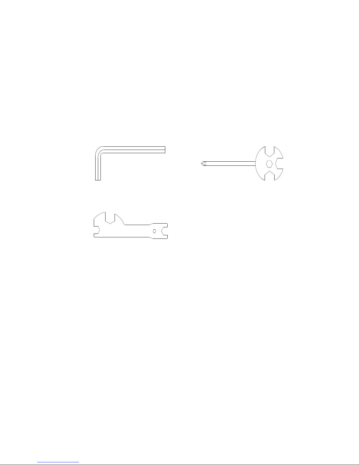
TOOLS
Allen
Wrench S6
1 PC
skrutklovač
Multi Hex Tool with Phillips
Screwdriver
S10, S13, S14, S15
1 Pcmultifunkčný
šestuholníkový skrutkovač
Multi Hex Tool
S10, S13, S17,
S19
1 PC
Multifunkčný
skrutkovač

OVERVIEW DRAWING
ASSEMBLY INSTRUCTIONS
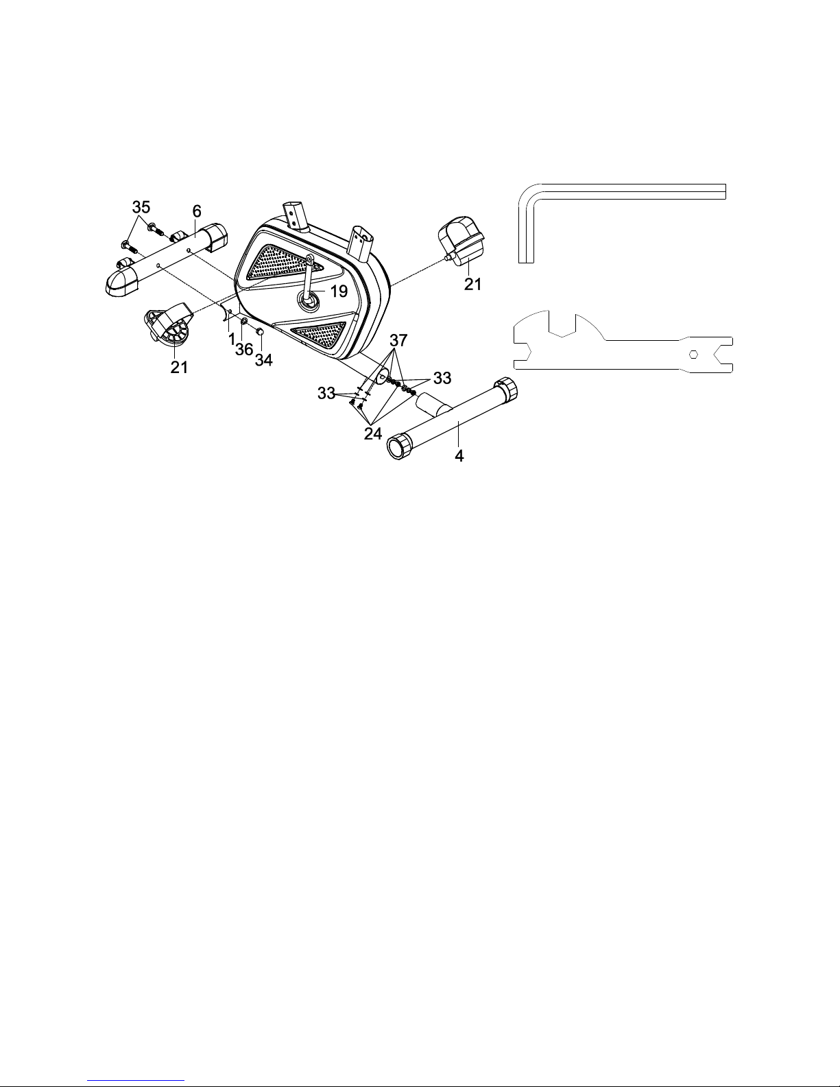
1. Front/Rear Stabilizers and Right/Left Foot Pedals Installation
Remove four M8x15 Bolts (24), four Ø8 Spring Washers (33), and four Ø20xØ8xδ1.5
Curve Washers (37) from the Rear Stabilizer (4). Remove bolts with the S6 Allen Wrench
provided.
Attach the Rear Stabilizer (4) into the Main Frame (1) with four M8x15 Bolts (24), four Ø8
Spring Washers (33), and four Ø20xØ8xδ1.5 Curve Washers (37) that were removed.
Tighten bolts with the S6 Allen Wrench provided.
Position the Front Stabilizer (6) in front of the Main Frame (1) and align bolt holes.
Attach the Front Stabilizer (6) onto the front curve of the Main Frame (1) with two M10 Cap
Nuts (34), two M10x57 Bolts (35), and two Ø10 Big Curve Washers (36). Tighten nuts with
the Multi Hex Tool provided.
Foot Pedals Installation
The Cranks, Pedal Shafts and Pedal Straps are marked “R” for Right and “L” for Left.
Insert the pedal shaft of Left Foot Pedal (20) into threaded hole in the left Crank (19).
Turn the pedal shaft by hand in the counter-clockwise direction until snug.
Note: DO NOT turn the pedal shaft in the clock ise direction, doing so ill strip the
threads.
Tighten the pedal shaft of Left Foot Pedal (20) with the Multi Hex Tool provided.
Insert pedal shaft of Right Foot Pedal (21) into threaded hole in right Crank (19).
Allen Wrench S6
Multi Hex Tool
S10, S13, S17, S19
Tool:
Turn the pedal shaft by hand in the clockwise direction until snug.
Tighten pedal shaft of Right Foot Pedal (21) with the Multi Hex Tool provided.
I
1.
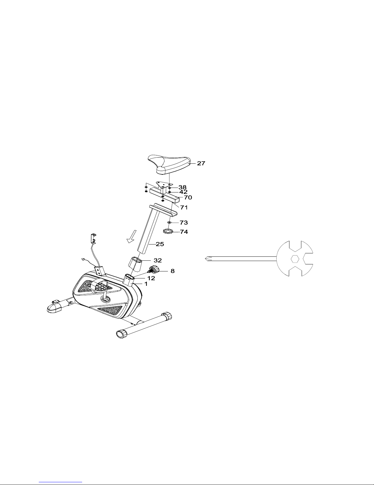
2. Seat Post, Seat Post Cover, Seat Cushion, and Seat Sliding Tube Installation
Slide the Seat Post Cover (32) onto the tube of the Main Frame (1).
Insert the Seat Post (25) into the Seat Post Bushing (12) on the tube of the Main Frame (1)
and then attach the M16x1.5 Seat Post Knob (8) onto the tube of the Main Frame (1) by
turning it in a clockwise direction to lock the Seat Post (25) in the suitable position.
Remove three Ø16xØ8x1.5 Washers (38) and three M8 Locknuts (42) from underside of
the
Multi Hex Tool with Phillips Screwdriver
S10, S13, S1 , S15
Tool:

Seat Cushion (27). Remove locknuts with the Multi Hex Tool with Phillips Screwdriver
provided.
Guide bolts on underside of the Seat Cushion (27) through holes on top of the Seat Sliding
Tube (70), attach with three removed Ø16xØ8x1.5 Washers (38) and M8 Locknuts (42).
Tighten nylon nuts with the Multi Hex Tool with Phillips Screwdriver provided.
Guide the Seat Sliding Tube Bolt (71) on underside of the Seat Sliding Tube (70) through
hole on top of the Seat Post (25), attach with one Ø20xØ10x2 Big Washer (73) and M10
Seat Adjustment Knob (74).
3. Handlebar Post and Tension Control Knob Installation
Remove four M8x10 Bolts (39), four Ø16xØ8x1.5 Washers (38), one M8x15 Bolt (24), and
one Ø20xØ8xδ1.5 Curve Washer (37) from the Main Frame (1). Remove bolts with the S6
Allen Wrench provided.
Slide the Handlebar Post Cover (31) up to the Handlebar Post (3).
Insert the Tension Cable (54) through into the bottom hole of Handlebar Post (3) and pull it
out from the square hole of Handlebar Post (3).
Connect the Sensor Wire (26) from the Main Frame (1) to the Extension Sensor Wire (59)
from the Handlebar Post (3).
Insert the Handlebar Post (3) onto the tube of the Main Frame (1) and secure with four
M8x10 Bolts (39), four Ø16xØ8x1.5 Washers (38), one M8x15 Bolt (24), and one
Ø20xØ8xδ1.5 Curve Washer (37) from the Main Frame (1) that were removed. Tighten
bolts with the S6 Allen Wrench provided. Slide the Handlebar Post Cover (31) down to the
Main Frame (1).
Remove the Ø5xØ20xδ1.5 Big Washer (46) and M5x20 Bolt (57) from the Tension Control
Knob (7). Remove bolt with the Multi Hex Tool with Phillips Screwdriver provided.
Put the cable end of resistance cable of Tension Control Knob (7) into the spring hook of
Tension Cable (54), see Figure A. Pull the resistance cable of Tension Control Knob (7) up
and force it into the gap of metal bracket of Tension Cable (54) , see Figure B. Attach the
Tension Control Knob (7) onto the Handlebar Post (3) with the Ø5xØ20xδ1.5 Big Washer
(46) and M5x20 Bolt (57) that were removed. Tighten bolt with the Multi Hex Tool with
Phillips

4. Handlebar and Computer Installation
Remove two M8x15 Bolts (24) and two Ø16xØ8x1.5 Curve Washers (64) from the
Handlebar Post (3). Remove bolts with the S6 Allen Wrench provided.
Insert the Hand Pulse Sensor Wires (53) into the hole on the Handlebar Post (3) and then
pull them out from the top end of the Handlebar Post (3).
Attach the Handlebar (2) onto the Handlebar Post (3) with two M8x15 Bolts (24) and two
Ø16xØ8x1.5 Curve Washers (64) that were removed. Tighten bolts with the S6 Allen
Wrench provided.
Remove four M5x12 Bolts (47) from the Computer (10). Remove bolts with the Multi Hex
Tool with Phillips Screwdriver provided.
Connect the Hand Pulse Sensor Wires (53) and Extension Sensor Wire (59) to the wires
that come from the Computer (10). Tuck wires into the Handlebar Post (3).
Attach the Computer (10) onto the top end of the Handlebar Post (3) with four M5x12 Bolts
(47) that were removed. Tighten bolts with the Multi Hex Tool with Phillips Screwdriver
provided.
Allen Wrench
S6
Multi Hex Tool with Phillips
Screwdriver
S10, S13, S1 , S15
Tool:

OPERATING THE COMPUTER
USING YOUR COMPUTER
The computer can be activated by pressing the buttons or by
pedaling. If you leave the equipment for 4 minutes, the power will
turn off automatically.
BUTTON FUNCTIONS:
MODE: Press the MODE button to select each function of the
computer.
Press and hold the MODE button for 4 seconds to reset all data values to zero except the
ODO (ODOMETER) data values.
COMPUTER FUNTIONS:
SCAN: Press the MODE button until the arrow points to SCAN, the computer will
automatically scans each function in sequence with change every 5 seconds.
NOTE: If you do not want to use the SCAN function, press the MODE button to select one
of
the other functions.
TIME: Press the MODE button until the arrow points to TIME, the computer will display your
elapsed workout time in minutes and seconds.
SPEED: Press the MODE button until the arrow points to SPEED, the computer will display
the current training speed.
CAL (CALORIES): Press the MODE button until the arrow points to CAL, the computer will

display the total accumulated calories burned during workout.
PULSE: Press the MODE button until the arrow points to PULSE and then hold both two
hands on handlebar grip sensors, the screen will display your current heart rate figures and
a heart symbol. To ensure the pulse readout is more precise, please always hold on to the
handlebar grip sensors with two hands instead of just with one hand only when you try to
test your heart rate figures.
DIST (DISTANCE): Press the MODE button until the arrow points to DIST, the computer will
display the accumulative distance traveled during workout.
ODO (ODOMETER): Press the MODE button until the arrow points to ODO, the computer
will display the total accumulative distance.
ODO(ODOMETER):
Zobrazuje akumulační celkovou ujetou vzdálenost. Datové hodnoty zobrazuje ODO stisknutím a
přidržením MODE nebo RESET po dobu 3 sekund. Pokud budete mít dobrou baterii z počítače , budou
ODO dataValues
HOW TO INSTALL THE BATTERIES:
1. Remove the battery cover on the back of the computer.
2. Place one "SIZE-AAA" batteries into the battery housing.
3. Insure batteries are correctly positioned and battery springs are proper contact with
batteries.
4. Re-install the battery cover.
5. If the display is illegible or only partial segment appear, remove batteries and wait 15
seconds before reinstalling.
ADJUSTMENTS
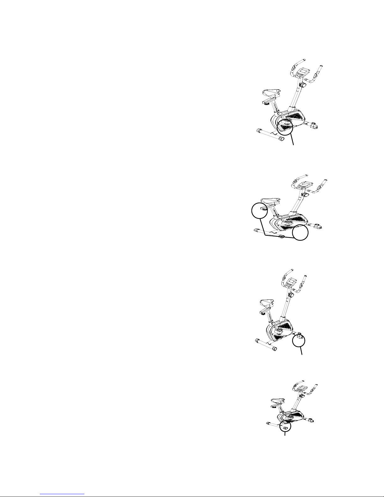
Adjusting the Tension Control Knob
To increase the load, turn the tension control knob in
a
clockwise direction.
To decrease the load, turn the tension control knob in
a
counterclockwise direction.
Adjusting the Rear Stabilizer End Cap
Turn the rear stabilizer end cap on the rear stabilizer
as
needed to level the upright bike.
Adjusting the Seat Height
Turn the seat post knob in a counterclockwise
direction
until it can be pulled out. Pull out the seat post knob
and then slide the seat post up or down direction to
the
suitable position. Lock the seat post in place by
releasing the seat post knob and sliding the seat post
up
or down slightly until the seat post knob "pops" down
into the locked position. For added safety, tighten the
seat post knob in a clockwise direction.
NOTE: When adjusting the height of seat post,
make
sure the seat post bushing does not exceed the
mark line on the seat post.
Tension Control Knob
Rear Stabilizer End Cap
Seat Post Knob
Seat Adjustment Knob

Adjusting the Seat For ard or Back
Turn the seat adjustment knob to loosen the seat sliding
tube. Slide the seat sliding tube forward or back to
desired position and turn seat adjustment knob to
tighten.
NOTE: Continue to turn seat adjustment knob until
seat sliding tube is secure before exercising.
MAINTENANCE
Cleaning
The upright bike can be cleaned with a soft cloth and mild detergent. Do not use abrasives
or solvents on plastic parts. Please wipe your perspiration off the upright bike after each
use. Be careful not get excessive moisture on the computer display panel as this might
cause an electrical hazard or electronics to fail.
Please keep the upright bike, specially, the computer console, out of direct sunlight to
prevent screen damage.
Please inspect all assembly bolts and pedals on the machine for proper tightness every
week.
Storage
Store the upright bike in a clean and dry environment away from children.
Skladování
Skladujte vzpřímené kolo v suchém a čistém prostředí mimo dosah dětí
TROUBLESHOOTING
WARM UP AND COOL DOWN ROUTINE
The WARM-UP is an important part of any workout. The purpose of warming up is to

prepare your body for exercise and to minimize injuries. Warm up for two to five minutes
before aerobic exercising. It should begin every session to prepare your body for more
strenuous exercise by heating up and stretching your muscles, increasing your circulation
and pulse rate, and delivering more oxygen to your muscles.
COOL DOWN at the end of your workout, repeat these exercises to reduce soreness in
tired muscles. The purpose of cooling down is to return the body to its resting state at the
end of each exercise session. A proper cool-down slowly lowers your heart rate and allows
blood to return to the heart.
ROLLS
Rotate your head to the right for one count, you should feel a
stretching sensation up the left side of your neck. Then rotate your
head back for one count, stretching your chin to the ceiling and
letting your mouth open. Rotate your head to the left for one count,
then drop your head to your chest for one count.
SHOULDER LIFTS
Lift your right shoulder toward your ear for one count. Then lift your
left shoulder up for one count as you lower your right shoulder.
SIDE STRETCHES
Open your arms to the side and lift them until they are over your head.
Reach your right arm as far toward the ceiling as you can for one
count. Repeat this action with your left arm.
QUADRICEPS STRETCH
With one hand against a wall for balance, reach behind you and pull
your right foot up. Bring your heel as close to your buttocks as
possible. Hold for 15 counts and repeat with left foot.
HAMSTRING STRETCHES
Extend your right leg. Rest the sole of your left foot
against your right inner thigh. Stretch toward your toe
as far as possible. Hold for 15 counts. Relax and then
repeat with left leg.
CALF/ACHILLES STRETCH
Lean against a wall with your left leg in front of the right and
your arms forward. Keep your right leg straight and the left
foot on the floor; then bend the left leg and lean forward by
moving your hips toward the wall. Hold, then repeat on the
other side for 15 counts.
TOE TOUCHES
Slowly bend forward from your waist, letting your back and
shoulders relax as you stretch toward your toes. Reach as far as
you can and hold for 15 counts.
I
NNER THIGH STRETCH
Sit with the soles of your feet together and your knees pointing
outward. Pull your feet as close to your groin as possible.
Gently push your knees toward the floor. Hold for 15 counts.

Table of contents
Other Spartan Exercise Bike manuals

Popular Exercise Bike manuals by other brands

RAD Cycle Products
RAD Cycle Products 1104 Gonzo instruction manual

Tunturi
Tunturi Pure U bike 8.1 user manual

Sportplus
Sportplus X-Bike SP-HT-1002 operating instructions

Stamina
Stamina 15-1101 owner's manual

YOSUDA
YOSUDA YB007R Installation and operation manual

Hoist Fitness
Hoist Fitness L-90900 owner's manual

Kettler
Kettler PASO 200 Assembly instructions

NordicTrack
NordicTrack Sl 728 Contour Plus manual

Duke Fitness
Duke Fitness HOMETRAINER XB40 Assembly and operating instructions

Diamondback
Diamondback APEX U6 owner's manual

Hammer
Hammer NorsK CardioPace 5.0 manual

Kettler
Kettler GIRO R3 Assembly instructions


