Spatherm SEO S User manual

Installation and Operating Manual
SEO S and SEO L stoves

GB 2
PREFACE / QUALITY PHILOSOPHY
You have decided in favour of a Spartherm stove; thank you for your confidence
in our company.
In a world of excess and mass production, our company stands for the values
expressed by our owner, Gerhard Manfred Rokossa:
„High technical quality combined with contemporary design and service to the
satisfaction of our customers so they will recommend us to others“.
Together with our specialist trade partners, we offer a range of first-class products,
which not only evoke passion, but also engender feelings of comfort and secu-
rity. To ensure that this occurs, we encourage you to read the operating manual
carefully so that you can become familiar with your fireplace and its accessories
quickly and thoroughly.
In addition to information on use, these instructions also include important details
on care and operation to guarantee your safety and to protect the value of your
stove as well as useful tips and guidance. Moreover, we show you how you can
operate your stove in an environmentally responsible manner.
For further enquiries, please contact your specialist dealer.
We hope you enjoy your new stove.
Your Spartherm team
G.M. Rokossa

GB
GB 3
CONTENTS
1. General notes 4
1.1 Quality control 5
1.2 Scope of Delivery 5
1.3 Transport damage 5
2. Installation instructions 5
2.1 Fundamental requirements for installation 6
2.1.1 Installation site 6
2.1.2 Multiple connection 6
2.2 Technical data 7
2.3 Installation / assembly 9
2.3.1 Changing the flue gas connection direction 9
2.4 Combustion air supply 10
2.4.1 Open flue operating method 10
2.4.2 Separate combustion air supply 11
2.4.3 Closed flue operation 12
2.5 Fire protection 12
2.6 Shut-off devices 15
2.7 Connecting pieces 15
2.8 Integrated throttle valve 15
2.9 Closing force for the fire door 16
3. Operating Manual 17
3.1 General information on operation 17
3.2 S-Thermatik NEO 18
3.3 Function of the rotary-base for SEO S 18
3.4 Rating plate 19
4. Combustion 19
4.1 Initial commissioning 19
4.2 SEO operating concept 20
4.2.1 The ‘SEO app’ 20
4.2.2 The indicator 20
4.2.3 Start and menu structure of the app 21
4.2.4 Starting level 22
4.2.5 Fire area 22
4.2.6 Mode 23
4.2.7 Settings 23
4.2.8 Assistance 24
4.2.9 Fire 24
4.2.10 Monitor 25
4.2.11 Example of menu guidance 25
4.3 Heating-up / firing 26
4.3.1 Refuelling 27
4.3.2 Hourly wood consumption rate 27
4.4 Controlling heat output 27
4.5 Room heating options / indoor climate 27
4.6 Heating in the shoulder seasons/during unfavourable weather condi-
tions 28
4.7 Chimney fire 28
5. Fuel 28
5.1 CO2Neutrality 29
5.1.1 Wood storage 29
5.2 Your contribution to environmental protection 30

GB 4
6. Cleaning and care 30
6.1 Cleaning the firebox/cladding parts 30
6.2 Firebox lining 31
6.2.1 Firebox lining SEO S 31
6.2.2 Firebox lining SEO L 32
6.3 Maintenance 32
6.3.1 Lubrication manual for door latches with Smart-Close 32
7. Troubleshooting 33
7.1 Glass becomes sooted heavily, rapidly and unevenly 33
7.2 Fire is difficult to ignite 33
7.3 Smoke escapes when adding wood 34
7.4 Excessively rapid burn-up /
rate of wood consumption is too high 34
8. General warranty conditions 34
8.1 Application area 34
8.2 General information 34
8.3 Warranty period 34
8.4 Requirements for this warranty to be effective 35
8.5 Exclusion of warranty 35
8.6 Rectification of defects / repair 35
8.7 Extension of the warranty period 36
8.8 Replacement parts 36
8.9 Liability 36
8.10 Final comments 36
9. SEO S / L commissioning protocol 37
1. GENERAL NOTES
Please consult your district master chimney sweep before assembling and
installing your SEO stove. He will advise you of building law regulations, the
suitability of your chimney, and will conduct the ac-ceptance procedure for
your stove. The chimney calculation is executed in accordance with DIN EN
13384 with the value triplet specified in this manual (see technical data).
Important for small children, elderly or infirm persons: As is the case
with all heating devices, it is expedient that you attach a protective fixture
for these groups of persons, as the view pane and the cladding parts of the
stove can become extremely hot! Danger of burn injuries!
Never leave these groups of persons unattended near the stove when a
fire is burning or has just been extinguished! The stove should never be
operated for an extended period of time unattended.
ATTENTION: The heat-resistant glove provided serves only as thermal pro-
tection when using the operating handle and the cold hand. The glove is
not fire-proof!
National and European standards, the respective state-specific and local
directives and regulations, in particular the respective firing installation
ordinance of the German Federal State, must be complied with for setup
and operation of your stove and for the connection to the chimney.
The stove must always be operated with the door closed. Modification of the
closing device is prohibited!

GB
GB 5
1.1 QUALITY CONTROL
OUR STOVE HAS BEEN TESTED IN ACCORDANCE WITH DIN EN 13240
AND SATISFIES THE REQUIREMENTS STIPULATED IN THE CONSTRUC-
TION PRODUCTS DIRECTIVE. (DECLARATION OF PERFORMANCE IS
AVAILABLE AND CAN BE VIEWED AT WWW.SPARTHERM.COM)
These stoves have a self-closing fire door which means the door is only
opened when the fireplace has to be serviced (e.g. to clean the combus-
tion chamber or add more fuel). For safety reasons, the closing mechanism
must not be tampered with; furthermore, any such action would render the
warranty and operating licence null and void. The warranty and operating
licence are also rendered invalid if the customer modified the technology of
any other area of the stove.
1.2 SCOPE OF DELIVERY
The SEO S and SEO L stoves have the following characteristics:
• Fireplace made of refractory concrete / chamotte
• Primary and secondary air supply
• Extractable ash drawer
• Self-closing fire door with high-temperature-resistant ceramic glass.
• Insulated glove*
• Flue pipe Ø 150mm / 500mm - EN 1856-2**
• Rating plate (cf. Chapter 3.4 “Rating plate” on page 33 for fitting details).
• Supplied pre-assembled in transport-friendly disposable cardboard
packaging
**Attention: The glove provided serves only as thermal protection and is
not fireproof.
** only part of SEO L
1.3 TRANSPORT DAMAGE
Immediately on arrival, please check the goods delivered (visual inspection).
Make a note of any damage on your delivery document. Inform your stove or
fireplace fitter of the damage before the installation work begins. Protect the
visible elements of the stove from soiling and damage during installation.
Only permitted and sufficiently strong transport aids may be used to trans-
port the stove.
The following points must be noted to ensure safe and problem-free
transport.
• It should always be shipped in an upright position, or slightly tilted on
its back!
• If wheelbarrows are used for transport, always lay the backs of stoves
in them.
2. INSTALLATION INSTRUCTIONS
The assembly and installation of your SEO S and SEO L stove must be
carried out by a specialist. Before your stove is assembled and installed you
should meet with the master chimney sweep responsible for such matters
in your area to discuss the suitability of your chimney and the installation
location and to clarify other matters.

GB 6
2.1 FUNDAMENTAL REQUIREMENTS FOR
INSTALLATION
For installation, connection and operation of the SEO S and SEO L stoves,
all necessary national and European standards, TROL as well as local regu-
lations (DIN, DIN EN, state construction ordinances, firing ordinances, etc.)
must be complied with and applied! The list of regulations given below is
not exhaustive.
FeuVo /
LBO / VKF
Firing Installation Ordinance of the respective German Federal State /
State building or fire protection regulations VKF (Switzerland)
1. BlmschV Erste Verordnung zur Durchführung des Bundes-Immissionsschutzgesetz (First
Ordinance on the Implementation of the Federal Immission Control Act)
TROL Regulations of the German Tiled Stove and Air Heating Constructors Association
(ZVSHK)
DIN 1298 / EN 1856: Connecting flue pipes for heat generating systems
DIN EN 13240 Stoves / solid fuel room heaters
DIN 18896 Solid-fuel fireplaces Technical specifications for installation and operation
DIN EN 13384 Chimneys - Thermal and fluid dynamic calculation methods
DIN 18160-1/2 Chimneys / house chimneys
Artikel 15a B-VG (Austria)
Fireplaces may only be installed in rooms and places where the location,
construction situation and type of utilisation do not lead to hazards. The
floor area of the installation must be of a design and size such that the
fireplace can be operated properly and as intended.
2.1.1 INSTALLATION SITE
Your SEO S / SEO L stove must not be installed:
1. In stairways, unless they are in residential buildings with two or fewer
flats.
2. In hallways with general access.
3. in garages.
4. Fireplace systems in rooms or flats that are ventilated through ventila-
tion systems or warm air heating through the use of fans, unless the safe
operation of the stove is ensured.
5. In rooms in which highly combustible or potentially explosive substances
or mixtures are processed, stored or manufactured in quantities that
would be hazardous in the event of ignition or explosion
Closed flue stones can be installed in rooms, apartments or utilization units
of comparable size from which air can be extracted using fans, e.g. in ven-
tilation or hot air heating systems. The condition is that the vacuum-capable
equipment cannot create a vacuum > 8 PA.
2.1.2 MULTIPLE CONNECTION
Multiple use of the chimney in accordance with DIN 18160 is possible
because the SEO S / L stove has a self-closing fire door (type A1). Without
exception, this should always be discussed and agreed in advance with the
local chimney sweep. All fireplaces connected to a chimney must also be
approved for multiple connection!

GB
GB 7
2.2 TECHNICAL DATA
The following details refer to the conditions for type testing as defined in
EN13240. Depending on local conditions and individual operating methods,
deviations may arise on location for specific forms of operation.
Wood burning stove SEO S SEO L
Technical data:
Fuel type: Wood logs
Wood feed quantity: 1,5 1,6 kg/h
Nominal heat output 5,1 5,5 kW*
Thermal output range: 4,5-6,5 4,5-7,2 kW
corresponding wood consumption: 1,0-1,9 1,0-2,1 kg/h
Efficiency: 80 80 %*
CO content at 13% O2: < 1250 <1250 mg/Nm
Dust content: <40 <40 mg/Nm
Flue gas temperature at the connector1:309 283 °C*
Supply pressure**. 12 12 mbar
Mass flow of flue gas: 5,2 6g/s*
Combustion air requirement: 16,3 15,7 m³/h*
Weight according to model 240 225 kg
Minimum distances from combustible components: 1
back1:160 160 mm
side1:310 560 mm
top1:500 mm
Area of direct radiant heat1:* 800 mm
Requirements
BlmschV Stage 1 Yes
EN 13240 Yes
DIN Plus Yes
Regensburg municipal ordinance Yes
Munich municipal ordinance Yes
Aachen requirement Yes
15a (for Austria) Yes
Air cleanliness directive from 01.2011 (for Switzerland) Yes
**The specified values represent the mean value over a burn-up cycle.
These values arise under type testing conditions.
** Depending on the stove, negative pressures greater than 20-25 Pa can
influence correct operation. The viewing pane can become increasingly
contaminated or noise can be intensified!
1refer to 2.5 for details. Fire protection, illustrating installation variants.

GB 8
Dimensional drawing of SEO S Dimensional drawing of SEO L

GB
GB 9
2.3 INSTALLATION / ASSEMBLY
Your SEO S / SEO L stove must be installed on floors made of non-flammable
materials with a sufficient load-bearing capacity. Please observe the overall
weight (cf. Chapter 2.2 Technical data on page 7)! The load-bearing capac-
ity may have to be ensured by a sufficiently thick board (weight distribution).
When selecting the installation site, also note the necessary measures for
fire protection in the floor area (cf. Chapter 2.5 Fire protection on page 12).
The stove is placed on the floor in compliance with the safety distances (cf.
Chapter 2.5 Fire protection on page 12) and aligned horizontally. The feet
are adjustable in height.
2.3.1 CHANGING THE FLUE GAS CONNECTION
DIRECTION
The stove is prepared for the flue gas connection at the top when delivered.
The flue gas connection position can be changed to the back. If the position
of the flue gas connection is changed, the following assembly steps must
be performed:
Installation from back to top
As a first step, remove the top sealing cover by pulling it forwards. Lift off
the blanking plate with the help of the recessed aperture. Dismantle the
inner cover plate by unfastening the two screws (Fig. 2a).
In the next step, remove the flue gas connector on the back of the stove by
unfastening the hexagon screws (waf 13 mm) (Fig. 2b).
Fit the unfastened connection journal at the top of the stove connection
flange (Fig. 2c) with the help of the two hex screws. Now fit the cover plate
removed in step 1 back to the inside rear wall panel using the two screws.
Seal the outer rear cladding panel with the help of a second cover plate
supplied in the stove combustion chamber.
Finally, slide the cladding cover removed in step 1 back onto the top plate
(Figs. 2d+2e).
Make sure that the sealing elements are correctly positioned under the
dummy cover and the flue gas outlet and ensure a tight seal.
Note for SEO S: If the SEO S model is connected to the rear flue point, this
blocks the turning function!
1. Remove the 3 cladding parts at the top in the following sequence (Fig.
2a):
- Cap (forwards)
- Blanking plate (upwards)
- Inside cover plate (upwards)
2. Remove the back connecting socket by unfastening the two screws (Fig.
2b)
3. Fit the connecting socket on the top appliance flange using 2 screws
(Fig. 2c).
4. Fit the 3 back cladding parts (Figs. 2d+2e)

GB 10
Fig. 2a Fig. 2b
Fig. 2c Fig. 2d
Fig. 2e
1
2
3 4
4
5 6 7
1Blanking 5Cover plate, inside
2Cover plate, inside 6Cover plate, outside
3Cap 7Cladding cover
4Pipe nozzle
Installation from top to rear occurs in reverse order:
2.4 COMBUSTION AIR SUPPLY
The combustion air can be supplied in accordance with Chapter 2.4.1 Open
flue and Chapter 2.4.3 Closed flue in different ways.
2.4.1 OPEN FLUE OPERATING METHOD
Your ambiente SEO S / SEO L stove draws the combustion air from the
installation area (open flue operation). Ensure that there is a sufficient sup-
ply of fresh air to the installation area (for more details, refer to the appli-
cable regional Fire Installation Ordinance (German ‘FeuVO’), DIN 18896,
applicable rules of technology etc.).
The fresh air supply must be checked by the installer and the operator.
When operating several fireplaces in a single room or linked space, ensure
that sufficient air is available for combustion! It is possible that there is not
a sufficient supply of fresh air if the windows and doors are sealed (e.g., in
combination with energy saving measures).
As a result, the ventilation of the stove can be affected. This can also
adversely affect your well-being and, potentially, your safety. If necessary,
an air valve must be installed near the pellet stove for the additional supply
of fresh air, or a combustion air line must be routed outwards (see 2.4.2) or
in a well-ventilated room (except for the heating room). In particular, ensure
that the necessary combustion air pipes are open during the operation of
the fireplace insert.
This means that simultaneous operation with a ventilation system (e.g.
extractor hood, bathroom fan, etc.) in the same room or connected space
can adversely affect the function of the stove (to the point of smoke or flue
gas accumulating in the living room, despite the firebox door being closed).
It is therefore prohibited to operate appliances of this kind simultaneously
with a fireplace without first taking appropriate precautionary measures.

GB
GB 11
2.4.2 SEPARATE COMBUSTION AIR SUPPLY
The stove can be supplied with combustion air separately. The separate
combustion air connection is located on the underside of the appliance
(Ø = 100 mm). The combustion air line to be attached can be connected
underneath or at the back. A connection is integrated in the plinth for a
bottom connection.
To connect up combustion air, the following steps must be taken.
Assembly of the combustion air channel on the underside of the
appliance:
1. Place the appliance above the combustion air port in the floor and
remove the cladding plate (Fig. 3a).
2. Next, remove the sealing cover (Fig. 3b).
3. Connect the combustion air neck to a flexible and removable combustion
air line. If the combustion air connection is rigid at floor level, the sepa-
rate combustion air nozzle supplied must be pushed into the connection
to form an airtight seal.
4. Finally, press together the combustion air line and install the combustion
air neck (Fig. 3c).
Fitting the combustion air channel to the back of the appliance:
1. First of all, unscrew the outer and inner cover plates (Fig. 3d).
2. Now fit the combustion air nozzle (Figs. 3e+f).
3. Lastly, connect the combustion air nozzle with the combustion air line.
When connecting a pipe connection to the combustion air neck, the com-
bustion air can be supplied to the stove from the outside or from other
rooms such as the cellar. When connecting the stove to a combustion
air line, the TROL instructions (technical rules), DIN 18896, etc. must be
observed and applied.
1Cladding plate
2Cap
3Combustion air neck
In particular, ensure that the dimensions of the pipes are adequate!
2
3
Fig. 3a Fig. 3b
Fig. 3c Fig. 3d
Fig. 3e
1
Fig. 3f
2
3
3

GB 12
The combustion air openings and lines must not be closed or blocked unless
it has been ensured that the fireplace can only be operated with an open
lock by means of special safety equipment. The cross-section must not be
narrowed by a fastening or a grille. A shut-off valve must be installed, if
this combustion air feed pipe runs outside the building. In doing so, it must
be possible to easily determine the shut-off device setting from outside of
the connecting line. This arrangement allows the feed pipe to be insulated
to guard against the formation of condensation. The pipe should be posi-
tioned so that no water or other foreign substances from outside cannot get
into the stove, and that any condensation formed can run out of the pipe.
Even with a separate combustion air line for the stove, its operation can be
impaired by a ventilation system. Therefore, simultaneous operation is not
possible.
In accordance with regulations, combustion air lines crossing a fire wall in
buildings with more than two floors must be established in such a manner
that smoke or fire cannot be transmitted to other floors or fire compart-
ments. Country-specific and local fire safety regulations must be observed!
2.4.3 CLOSED FLUE OPERATION
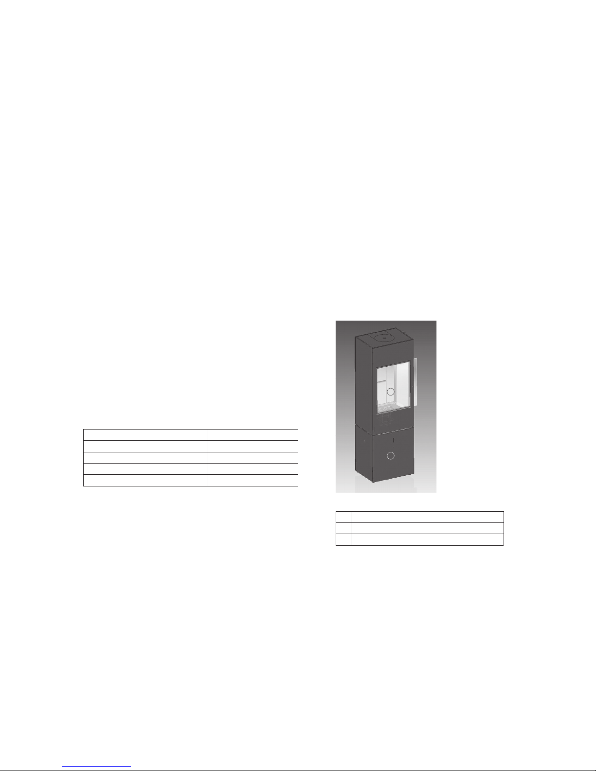
The SEO S / SEO L closed flue stoves have been developed for use with
residential ventilation systems for a vacuum range of up to 8 Pa in the
installation area and can be operated without additional safety equipment.
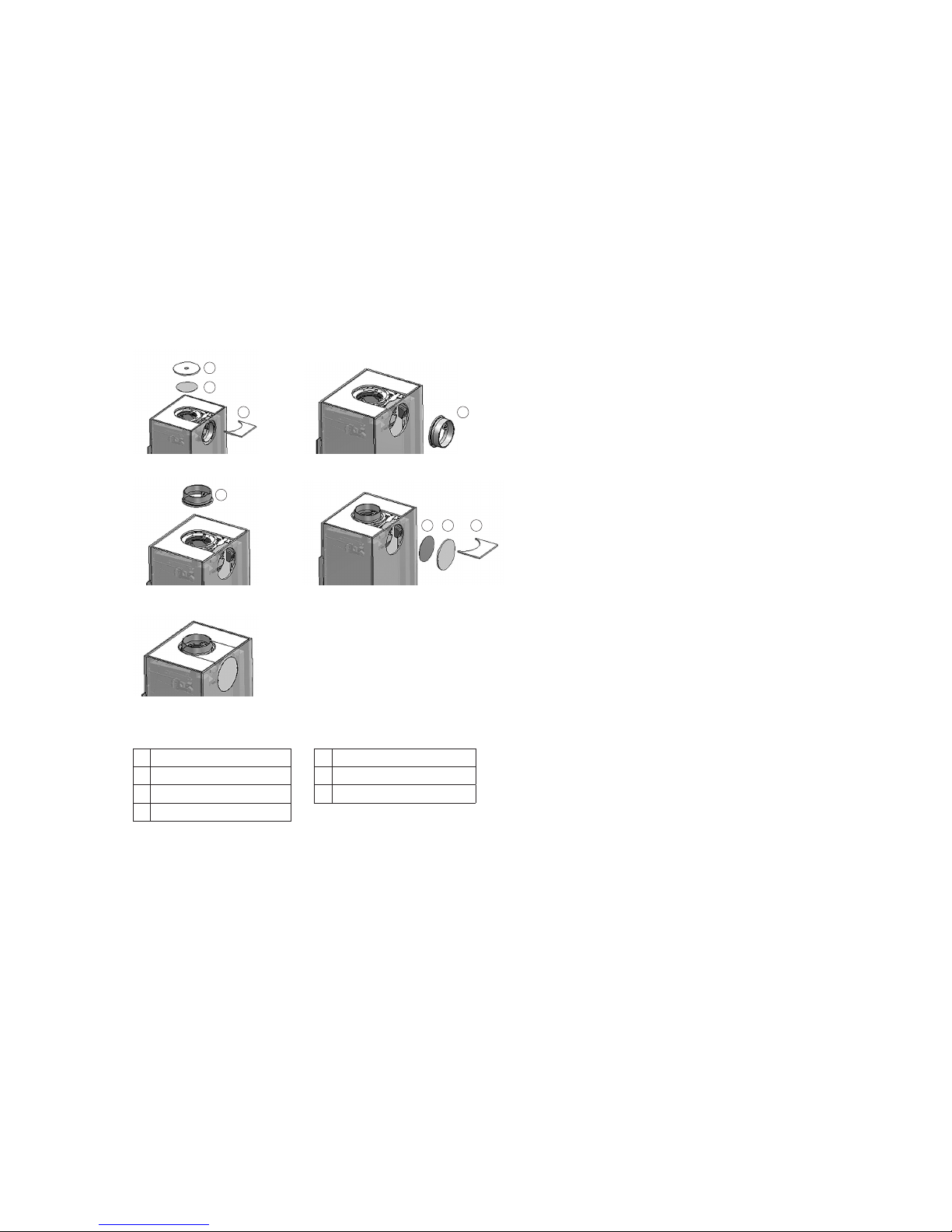
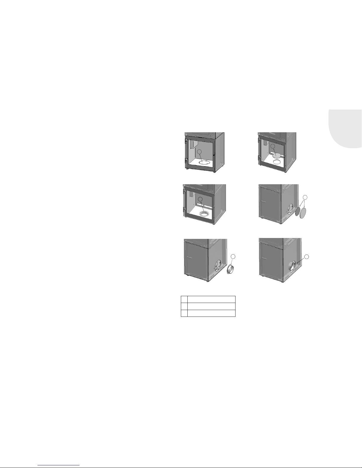
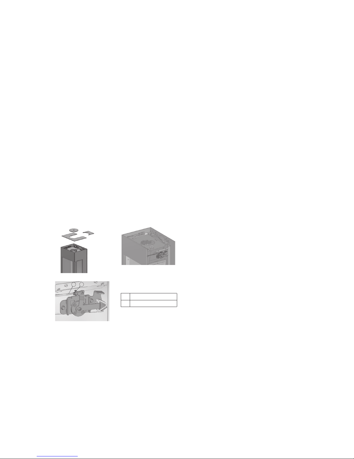
The combustion air must be supplied in airtight lines from the outside or
via an LAS system to the device for room-air-independent operation without
fail. To do this, the combustion air duct must be permanently sealed to the
combustion air neck (connection type back or bottom) of the stove.
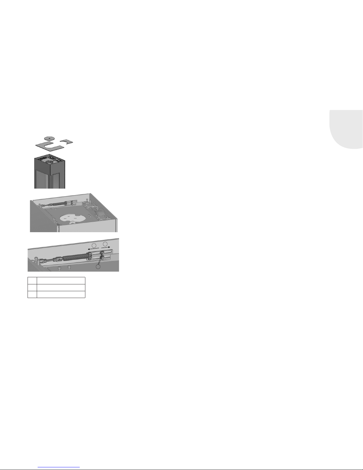
When connecting the close flue stove to a combustion air line, the TROL
instructions (technical rules) and DIN 18896, etc. must be observed and
applied. In particular, ensure that the dimensions are adequate! Comply
with all country-specific and local fire safety regulations! Make sure that
the pipes are always airtight.
2.5 FIRE PROTECTION
The handover inspection of your stove before commissioning is performed
by the chimney sweep responsible. You can also advise the chimney sweep
prior to installation about installation conditions on site, and can provide
advice on how to install your stove properly.
General information on fire prevention
Stoves are heat generators and are subject to regulations and necessary
measures for fire protection. Right from selection of the installation site
stage, fire regulations and recommended minimum individual clearances for
the appliance must be observed.
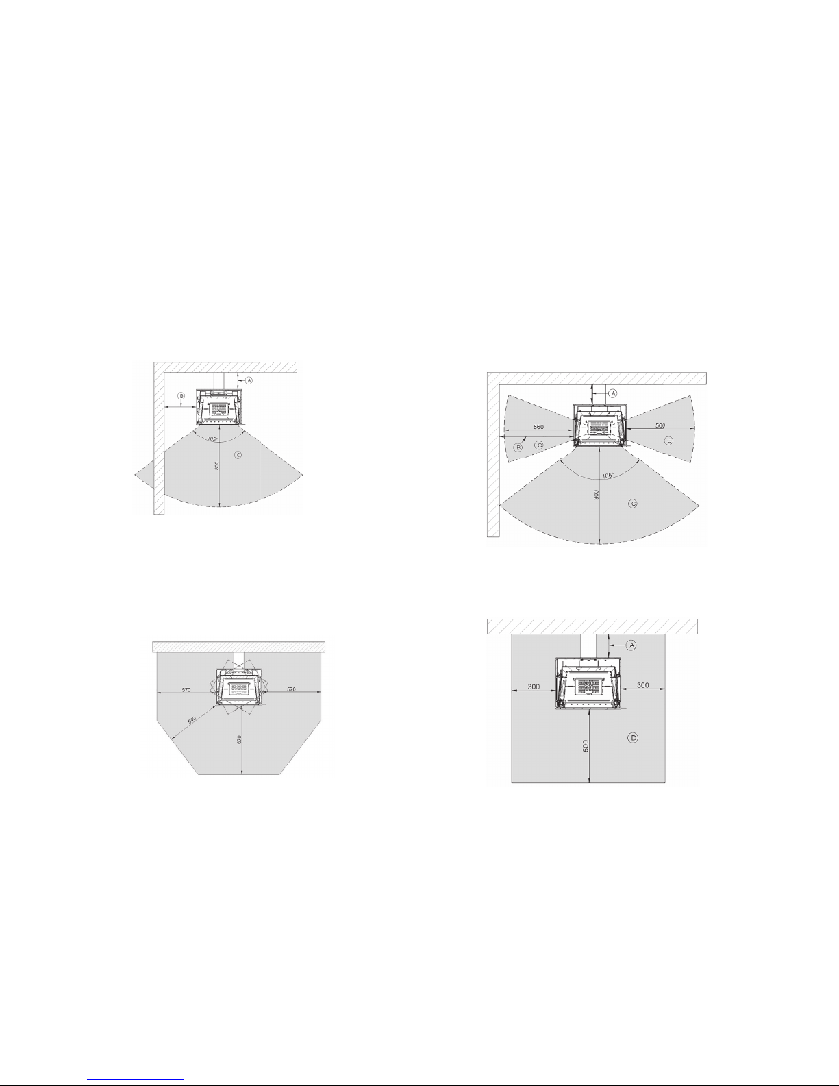
Basically, a minimum wall clearance of 5 cm to the back wall must be
adhered to. For reasons of safety and fire protection, make sure that large
distances to walls to be protected or combustible components are main-
tained. See the following installation examples.
The following table documents the permissible safety distances. Using the
diagrams (Figs. 4a-4f), match the mounting situation, taking into account
the specified distances that need to be complied with.
During installation, please pay attention to the fire protection instructions
and contact your local chimney sweep with any questions you may have.
• Mounting walls that are non-combustible or which do not require protec-
tion are able to withstand permanent exposure to tempera-tures > 85°C
thanks to their structure and material type.
• Combustible mounting walls in need of protection (e.g. stud partition
construction) must be protected from temperatures above 85°C.

GB
GB 13
Before installing the stove, it is necessary to evaluate the mounting walls. If
it is not possible to identify the precise type of installation wall, a specialist
(chimney sweep) needs to be brought in.
• Wallpaper as wall coverings in accordance with DIN 4102-1 are
non-combustible components and do not require special precautions
for fire protection. Ensure here that the underlying structure of the wall-
paper (e.g. timber frame construction) is very easily ignited or must be
protected and appropriate precautions must be taken!
• Ensure that the minimum clearances from chimney connecting piece to
combustible components are adhered to (see Chapter 2.7 Connecting
flue pipes on page 15).
• Combustible objects must not be located at a distance of 50 cm above
the fireplace!
Floor coverings near the fireplace:
Floors made of combustible materials in front of the firebox opening must
be protected by a board made of non-combustible materials. The board
must extend over at least 50 cm to the front and at least 30 cm to the side
(measured from the combustion chamber opening or viewing window)!
No combustible components, furniture, curtains or decorations may be
placed in the area of direct radiant heat of the fire door or inspection glass.
This distance may be reduced to 400 mm if radiation protection plates are
installed between the fireplace and combustible structures on both sides.
Installation example for the SEO S:
1. When installing against a straight wall, maintain the following distances
between that wall and your SEO S stove: a minimum distance of 160
mm must be maintained behind any combustible components (Fig. 4a)
2. For installation in the corner of a room, maintain the following wall dis-
tances: If the stove is installed as shown as in Figure 4b, a minimum
distance from the SEO S of 160 mm must be maintained to the sides of
combustible components.
Fig. 4a
Fig. 4b

GB 14
If the stove is installed as shown in figure 4c, a minimum distance of
160 mm at the back and of 600 mm at the side must be main-tained. If
the wall is in the radiant heat area, fit a thermal protector to this area.
3. For floor coverings in close range:
Floors made of combustible materials in front of the combustion cham-
ber opening must be protected by a board made of non-combustible
materials. The board must extend at least 670 mm to the front and at
least 570 mm to the side! Due to the fact that the SEO S fireplace can
rotate, the floor covering needs to be protected across a larger area
(Fig. 4d).
Abb. 4c
Abb. 4d
Installation example for the SEO L:
1. For installation against a straight wall, the following wall spacings must
be maintained to your SEO L stove: a minimum distance of 160 mm must
be maintained behind combustible components (Fig. 4e).
2. Floors made of combustible materials in front of the firebox opening
must be protected by a board made of non-combustible materials. The
board must extend at least 500 mm to the front and side! (Fig. 4f).
Abb. 4e
Abb. 4f

GB
GB 15
Stove
Distance to the
rear wall
Distance to side
wall
Distance in the area
of direct radiant
heat of the view
pane.
Dimensions of the
fire protection floor
covering
A (mm) B (mm) C (mm) D (mm)
combustible
No
protection
required
combustible
No
protection
required
combustible
No
protection
required
Length x
Width
Radius (with
round floor
covering)
SEO S 160 50 310 200 800 800 500 x 300 500
SEO L 160 50 560 250 800 800 500 x 300 500
2.6 SHUT-OFF DEVICES
Flue gas systems must be created as per the technical rules of the German
Association of Tiled Stove and Hot-Air Heating Systems.
Stoves must feature a shut-off valve on the exhaust path . These devices
must not be self-closing and must not be positioned such as to prevent or
hinder the inspection and cleaning of connecting pipework. The position of
the shut-off device must be visible from the outside, e.g., from the posi-
tion of the operating handle. Shut-off devices may only be installed in the
exhaust manifold or collecting pipe, the flue gas pipe stub or the pipeline
connecting piece.
2.7 CONNECTING PIECES
Connecting pieces: your SEO S / SEO L stove is connected to the chimney
by ø 150 mm connecting pieces made from steel sheet at least 2 mm thick.
These must comply with DIN 1298 or DIN EN 1856-2 and they must be
connected to the chimney in accordance with DIN 18160 or the regulations
that apply in the country concerned.
Ensure that the flue gas pipe is installed in the shortest possible route
upwards towards the chimney. The number of bends in the flue gas pipe
should be kept to a minimum. In addition, the flue gas pipe must be
connected to the chimney with a bricked-in wall lining and sealed. If neces-
sary, the flue pipe may need to be secured with brackets to assure sufficient
stability. If the flue gas pipe is routed through components with flammable
building materials, the flue gas pipe must be insulated as specified in the
regulations.
The connecting line must always be mounted in such a manner that it is
possible to clean the connecting line at any time. This must be ensured
through a sufficient number of cleaning openings.
Depending on the information provided by the flue gas pipe manufacturer,
the minimum distance from the chimney connecting piece to combustible
components may increase the distance between the stove and combustible
building components. The specified minimum distances to combustible
components as stated in these instructions refer to the fireplace and must
be adjusted if necessary (see Chapter 2.5 Fire protection).
Ensure that a cleaning opening is located above the flue pipe connection
with gas evacuation to the top.
2.8 INTEGRATED THROTTLE VALVE
A throttle valve is integrated in the exhaust flue above the deflector plate in
the SEO stove. When the fire door is closed, this throttle valve is in its start-
ing position. The exhaust gases can escape upwards through an opening
cross section in the sheet metal panel, optimally adjusted for combustion.
Whenever this fire is opened, e.g. for adding fuel, the throttle valve swivels
upwards, greatly increasing the opening aperture for the exhaust gases.
This ensures that the exhaust gases do not escape into the room as a result
of the change in pressure in chimney and combustion chamber while the
fire door is open.

GB 16
The initial position of this flap is set ex-factory for optimum air cross-sec-
tions. Depending on chimney conditions, this can cause impaired or insuf-
ficient combustion, and/or to smoke escaping into the room. In such cases,
it is possible to adjust the position of the throttle valve and therefore also of
the exhaust cross sections.
1. To do this, remove the top cladding parts from the top plate. (Fig. 5a).
2. Now you have access from above to the rod mechanism on the right side
of the stove that controls the throttle valve. The driving rod, mounted
with the help of a lock nut, can be used to adjust the position of the flap
(Figs. 5b and 5c).
3. To enlarge the opening cross section in the exhaust gas flue, unfasten
the lock nut and turn the driving rod further towards the back.
4. Then tighten down the lock nut again firmly.
5. Finally, place the cladding parts back onto the top plate.
Fig. 5a
Fig. 5b - Bottom view
Fig. 5c
1 2
1Driving rod.
2Lock nut
2.9 CLOSING FORCE FOR THE FIRE DOOR
The closing force of the self-closing Type A1 fire door is factory-set to its
optimum level. To change the closing force, the setting can be adjusted
using a spring.
1. To do this, remove the top cladding parts from the top plate. (Fig. 6a).
2. You now have access to the spring mechanism. (Fig. 6b).
3. Unfasten the two hex screws with flange and slide the holder in the two
elongated holes. You increase the closing force of the door by contin-
uing to tighten the spring (“tighten clockwise”), and you decrease the
closing force of the door by relieving tension on the spring (by turning it
anti-clockwise) (Fig. 6c).

GB
GB 17
Fig. 6a
Fig. 6b
12
3
1Reduce force
2Increase force
3Hex screws with flange
Fig. 6b
3. OPERATING MANUAL
Read these installation and operating instructions carefully before installing
and starting up your stove. All objects must be removed from the combus-
tion chamber (except for combustion chamber liner).
Ask your specialist dealer to explain to you how to operate the SEO S / SEO
L stove and how it functions.
National and European standards and local regulations for operating the
fireplace must be observed!
3.1 GENERAL INFORMATION ON OPERATION
• Small children, elderly or infirm persons: As is the case with all heating
devices, it is expedient that you attach a protective fixture for these
groups of persons, as the view pane and the lining parts of the stove can
become extremely hot! Danger of burn injuries!
• Never leave these groups of persons unattended near the stove when
a fire is burning or has just been extinguished! Make these individuals
aware of these risks.
• No combustible objects may be placed or laid on the free surfaces and
the panels of the SEO S / SEO L stove. Do not place items of clothing on
the stove to dry. Racks for drying clothing may only be placed outside
the radiation area!
• Burning fuel releases thermal energy which heats up the various parts
of the stove, such as the surfaces, the door, the door handle and con-
trol handle, the viewing pane, the flue ducts, etc. Do not attempt to
touch these components without adequate protection (i.e. heat-resistant
gloves).

GB 18
• The SEO S / SEO L stove may only be operated with the fire door closed.
The door should always be kept closed, even when cold. The door is only
opened for lighting up and for refuelling.
• The fireplace must never be modified! Do not insert any foreign com-
ponent (any component not expressly approved by Arcadia) into the
combustion chamber, combustion passages or exhaust gas flue. Any
such modification of the fireplace without express approval will void the
warranty and operating permit.
• This applies in particular when operating several fireplaces in a single
room or linked space. It must be ensured that sufficient air is available
for complete combustion!
• Your appliance is designed to operate as a temporary or short-term com-
bustion device. Continuous burning cannot be achieved even through
withdrawal of the combustion air and is not permitted! A longer heating
period is achieved by repeatedly by adding suitable amounts of fuel to
the fire.
3.2 S-THERMATIK NEO
Your SEO stove is equipped with S-Thermatik NEO burn-up equipment.
Supply voltage 230V AC
Power consumption during operation: approx. 10VA
Power consumption in "Stand-by" mode: approx. 6VA
Safety class I
Degree of protection IP 20
For further information about the burn-up control, please request the assem-
bly and service instructions from the manufacturer of the S-Thermatik NEO.
3.3 FUNCTION OF THE ROTARY-BASE FOR SEO S
Attention: The swivel function is not available when the exhaust flue gas
connection is at the back!
The SEO-S model is divided into two areas: the upper combustion area and
the lower maintenance and storage area. The upper section of the stove can
be turned by 30° in either direction using the rotary base at this interface
(Fig. 7a).
Fig. 7a
2
1
1Oberer Feuerungsbereich – lässt sich um 30° in jede Richtung drehen
2Lower maintenance and storage area
3Remove stop.

GB
GB 19
To activate the swivel function, you must first operate the stop on the rotary
base. This detent pin is located centrally in the lower storage area (Figs.
7b and 7c).
After pulling out the spring-actuated stop,
the top cube can be swivelled 30° in either
direction. After swivelling, lock the stove in
its final position by engaging the stop (Fig.
7d).
Fig. 7c
Fig. 7b
3
Fig. 7d
3.4 RATING PLATE
The rating plate is located on your warranty certificate and also on the
back of your stove. It contains technical data and notes. Never remove the
rating plate because it confirms that the appliance has been tested, and it
is also required for the acceptance procedure and annual inspections by the
chimney sweep.
4. COMBUSTION
4.1 INITIAL COMMISSIONING
The SEO S / SEO L stove must only be installed and set up by a special-
ised company. Initial commissioning must only be executed by an expert
employee of the installation company. A certificate confirming proper
installation and proper adjustment / function of all control components and
safety components must be given to the owner / operator of the system (see
sample, chapter 10).
When first putting your appliance into service, only start a moderate fire.
This enables you to avoid cracks in the firebox covering (which may still
contain residual humidity before the first firing). Slowly increase the heating
power to about 30% above nominal heat output by setting the fire 3 to 5
times to give the corrosion coating applied to the surfaces time to ‘burn
in’ properly. During this process, the paint can become slightly soft, do not
place any objects on the stove and do not touch the appliance. During this
burning-in process, an unpleasant yet harmless odour (sometimes accom-
panied by the build-up of smoke) may be given off. It is therefore important
to ensure that the room is well ventilated during the burning-in process.
Open all doors and windows to the outside of the building.

GB 20
During heating and cooling, metallic grinding noises may be heard as the
components of your stove expand or contract. These are completely normal
and arise as a result of material expansion caused by the high temperatures.
Note: It can be helpful for the lighting up to weigh the recommended
quantity of wood (1 - 1.5 kg) to estimate what (visual) quantity of wood
corresponds to this weight. This enables you to ensure that the stove is not
overheated as a result of you adding too much wood.
4.2 SEO OPERATING CONCEPT
4.2.1 THE ‘SEO APP’
Your SEO stove is controlled fully automatically by the integrated S-Ther-
matik NEO burn-up controller. To operate this appliance, the “SEO APP”
provides you with an information platform. With this, you can choose various
settings, e.g. the desired power/performance level, as well as request fur-
ther information about the prevailing operating condition, historical data or
information about suspected faults.
This app is available for devices running Android and the IOS operating
system. It is called “SEO App” and it can be downloaded from the Play Store
or from iTunes.
To install the app, you must activated Bluetooth on your device, and you may
need to permit “Installation from unknown sources”.
The data link only functions using Bluetooth. The module is integrated in
the control system. Only ever one mobile device can be connected to the
controller at any one time. Another device can log in once Bluetooth is
switched off on the connected device, or until that device moves outside
reception range.
Note: Depending on the configuration of the tablet or smartphone being
used, a Bluetooth coupling code can be requested during first-time instal-
lation. To enable the connection between the stove and the tablet or smart-
phone, please enter this numerical string:
0 0 0 0
in the input screen.
4.2.2 THE INDICATOR
An illuminated indicator acts as a direct information communicator between
the SEO stove and the operator. It is recessed into the lower door of the
storage compartment. This provides basic information about the prevailing
operating status. For further information, please consult the “SEO App”
This indicator provides basic information about the prevailing operating
status and of any faults/operating errors with a range of light signals: Off,
continuously lit, pulsating flashes and rapid flashes.
Interaction levels
Simple feedback during operation
More complex settings
Monitor
This manual suits for next models
1
Table of contents
Popular Stove manuals by other brands

Nobis
Nobis H14 V SHAPE Instructions for installation, use and maintenance manual

MHSC
MHSC CSDV20SNV Installation and operating instructions

Camplux
Camplux MS-7 instruction manual

Parmco
Parmco OV-M2-6S-9 Installation and operating instructions

Centek
Centek CT-1524 instruction manual

Russell Hobbs
Russell Hobbs RHEFSTV2003B user guide

deville
deville C07832 Manual Utilisation

Mendip
Mendip Sqabox unO Installation manual and operating instructions

Saey
Saey SORDO 80 Flatline operating instructions

Stanley
Stanley OISIN SF User instructions

Valor
Valor Portrait President FS Stove 531CSB installation manual

AGA
AGA Ludlow Installation & user manual