Spaun Electronic SMS 9982 NF User manual
Technische Hinweise
zu den DiSEqC-Multiswitchen der Premium-Class
SMS 9962 NF und SMS 9982 NF sowie zu
den kaskadierbaren Multiswitchen SMK 99xx F
!
Technische Verbesserungen, Änderungen im Design und Irrtümer vorbehalten. 104990/10.04
Byk-Gulden-Str. 22 • D-78224 Singen
Telefon: +49 (0) 7731 - 86730 • Telefax: +49 (0) 7731 - 64202
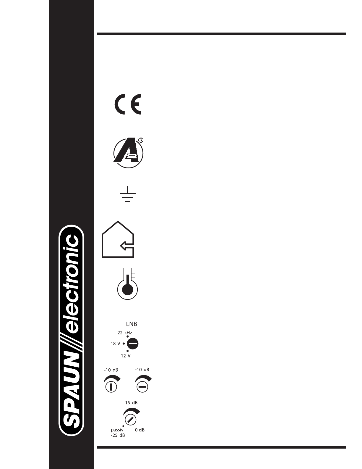
Mit der CE-Kennzeichnung bestätigt SPAUN die
Einhaltung der EMV-Anforderungen entsprechend
der EU Produktnorm EN 50083-2 und die
Einhaltung der Sicherheitsanforderungen ent-
sprechend der EU Produktnorm EN 50083-1.
Die Multiswitche erfüllen die erhöhten
Schirmungsmaß-Anforderungen gemäß
EN 50083-2, Güteklasse A.
Alle Komponenten sind zum Verbinden mit dem
Hauptpotentialausgleich mit einer Erdungsklemme
ausgestattet.
Wichtig: bitte nachfolgende Hinweise beachten!
Die Montage ist nur in trockenen Räumen und auf
nicht brennbarem Untergrund zulässig.
Netzgespeiste Geräte ausschließlich waagerecht
(Netzteil links oder rechts) montieren, um eine aus-
reichende Luftzirkulation zu erzielen.
Vorsicht bei Montage in Schalt- bzw. Zählerkästen !
Die zulässige Umgebungstemperatur beträgt:
-20° C ... +50° C.
Die richtige LNB-Fernspeisespannung einstellen.
Zur Inbetriebnahme die Eingangspegel für jede
SAT-ZF-Ebene ggf. angleichen.
Terrestrischen Eingangspegel anpassen
bzw. Terrestrik passiv schalten.
Kompakt-Multiswitche SMS 9962 NF und SMS 9982 NF
Einsetzbar
➜ als Einzelbaustein für 6 bzw. 8 Teilnehmer,
➜ zur Kaskadierung mit SMK 99xx F,
➜ als Nachverstärker oder
➜ als Abschlussbauteil in einer Kaskade.
Stromversorgung
• Die Kompakt-Multiswitche verfügen über interne, energiesparende
Schaltnetzteile (Eingangsspannungsbereich: U~ 100 ... 240 V, 50...60 Hz).
Fernspeisung
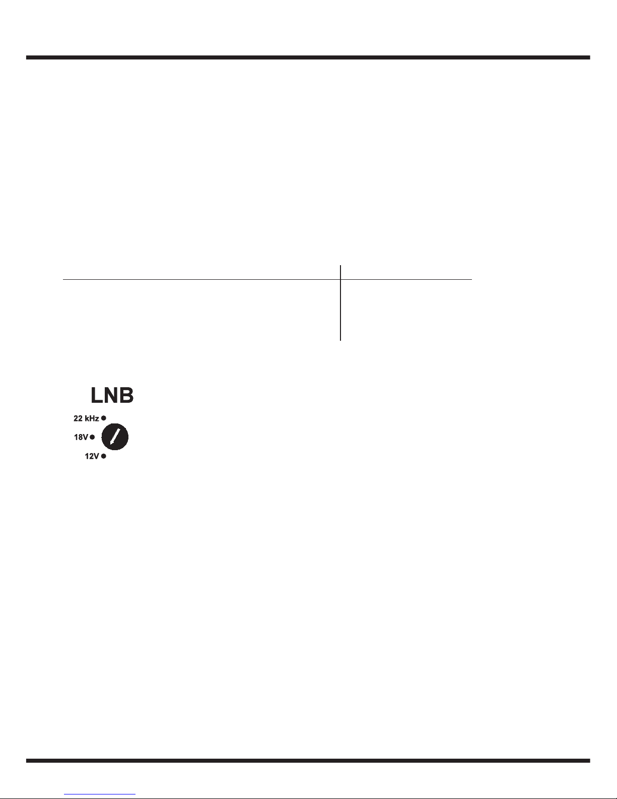
Für die LNB-Fernspeisung sind 3 Betriebsarten wählbar:
12 V: Alle 8 ZF-Eingänge ... führen 12 Volt Fernspeisung
(Betriebsart für SMATV / Quattro-LNBs).
18 V: Die vertikalen ZF-Eingänge führen 12 Volt und die horizon-
talen ZF-Eingänge führen 18 Volt (Betriebsart für Twin-LNBs).
22 kHz: Wie Schalterstellung 18 Volt, jedoch sind die High-Band
Eingänge mit 22 kHz moduliert (Betriebsart für Universal-
LNBs). Die Schalterstellung hat keinen Einfluss auf die
Steuersignale des Receivers !
• Für die LNB-Fernspeisung steht ein Fernspeisestrom von insgesamt 800 mA zur
Verfügung (maximal 400 mA pro Buchse).
Standby-Funktion
• Das Multiswitch-System verfügt über eine Standby-Funktion. Die Sat-ZF-Verstärker
und die Fernspeisung der LNBs sind nur aktiv, wenn mindestens ein Teilnehmer
(Receiver) im Multiswitch-System eine Fernspeisespannung zum Teilnehmerausgang
schickt. Dazu wird die 18 V-Spannung von Stamm bzw. auf Stamm durchge-
schaltet. Kaskadierte Multiswitche aktivieren übergeordnete Komponenten durch eine
Signalisierungsspannung auf Stammleitung .
• Der Einschaltimpuls der Fernspeisespannung vom Receiver erzeugt im Multiswitch
einen Rücksetzimpuls für den entsprechenden DiSEqC-Mikrocontroller. Dieser startet
danach im abwärtskompatiblen Modus (siehe analoge Schaltkriterien).
• Die terrestrische Verteilung bleibt von der Standby-Funktion unbeeinflusst.
!
Leistungsaufnahme (bei max. Stromabgabe): SMS 9962 / 9982 NF
SAT Standby Terrestrik passiv 3 W
Terrestrik aktiv 6 W
SAT aktiv Terrestrik passiv 36 W
Terrestrik aktiv 40 W
Terrestrik
• Der Eingang für terrestrische Signale verfügt über einen Pegelsteller ( 0...-15 dB ).
Der terrestrische Verstärkerzug (47 ... 862 MHz) ist durch eine integrierte
Gegentaktendstufe BK-tauglich.
• Die Terrestrik kann in den Multiswitchen SMS 9962 NF / 9982 NF komplett
passiv verteilt werden. Dazu muss der Pegelsteller bis zum Anschlag gegen den
Uhrzeigersinn gedreht werden. Der terrestrische Verstärker ist dann ausgeschaltet
und überbrückt. Gleichzeitig sind die Multiswitche dann rückwegtauglich!
• Terrestrische Antennensignale sollten den breitbandigen Eingängen der Multiswitche
zur Vermeidung von Störungen selektiv zugeführt werden (z.B. über "S"-taugliche
Mehrbereichsverstärker MBV... / MVF... bzw. selektive UKW-Bauteile wie UKW-
Bandpass FMP 30 oder UKW-Verstärker VFM.. F).
SAT-ZF-Verteilung
• Die ZF-Verstärkerzüge sind mit separaten Pegelstellern je ZF-Eingang ausgestattet.
Dadurch ist ein Angleichen der unterschiedlichen Signale um bis zu 10 dB möglich.
• Der max. Eingangspegel beträgt 90 dBµV bei jeweils eingedrehtem Pegelsteller und
Vollbelegung.
• Die ZF-Signale sind dem Multischalter entsprechend der Beschriftung zuzuführen,
damit die logische Zuordnung der ZF-Ebenen gemäß den Umschaltkriterien und
DiSEqC stimmt.
Max. Ausgangspegel
• Stammleitungen (SMS 99x2NF):
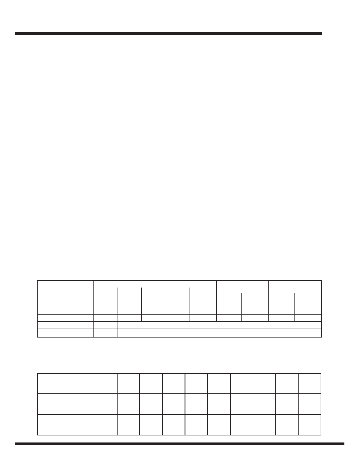
Vielkanalbetrieb
• Bei Vielkanalbetrieb sind die üblichen Pegelreduzierungen zu beachten:
CSO
47-450 MHz 108 107 101 103
47-606 MHz 106 105 98 98
47-862 MHz 105 101 94 90
950-2200 MHz 109 35 dB IMA / EN 50083-3
950-2200 MHz 111 35 dB IMA / EN 50083-3
Bereich
A: 19 K
C: 29 K
E: 42 K
94
––
––
92
––
––
dBµV / 60 dB / EN 50083-3
IMA3IMA2CTB CENELEC-
Raster
dBµV / 1R8-15
BK-Raster 36TV/24FM
CTB/72dB CSO/69dB
––
––
98
––
––
93
dBµV /
CTB/60dB
1TR8-1
CSO/60dB
28 analog + 63 digital
3
2
Anzahl der
Träger
2 4 6 8 10 12 16 24 36
Anzahl der
Verstärker
123456812 18
Pegelreduzierung
in dB
035678911 12
Teilnehmerausgänge (SMS 99x2 NF)
• Auskoppeldämpfung
Umschaltlogik
•Die Umschaltlogiken der Teilnehmerausgänge sind voneinander unabhängig und
können entweder mit den bekannten analogen Umschaltkriterien oder mit DiSEqC-
Befehlen angesteuert werden.
• Die Teilnehmerausgänge reagieren so lange auf die analogen Schaltkriterien, bis sie
einen gültigen DiSEqC Befehl erhalten. Alle analogen Schaltkriterien werden danach
bis zu einem Reset ( Unterbrechung der Fernspeisung oder Unterbrechung der
Netzversorgung oder DiSEqC-Befehl „Reset“) ignoriert. Ein gemischter Betrieb von
einem DiSEqC-Receiver und einem Receiver ohne DiSEqC ist an einem
Teilnehmerausgang möglich, wenn beim Receiverwechsel die Fernspeisung kurz
unterbrochen wird.
•Analoge Schaltkriterien:
- 14 V / 18 V zur Polarisationsumschaltung ( vertikal / horizontal )
- 0 kHz / 22 kHz zur Bandumschaltung ( unteres / oberes )
- TonBurst ( Orbitposition A / B )
•DiSEqC-Schaltkriterien:
Polarisation vertikal / horizontal
Band unteres / oberes ( low / high )
Position A ( Ost ) / B ( West )
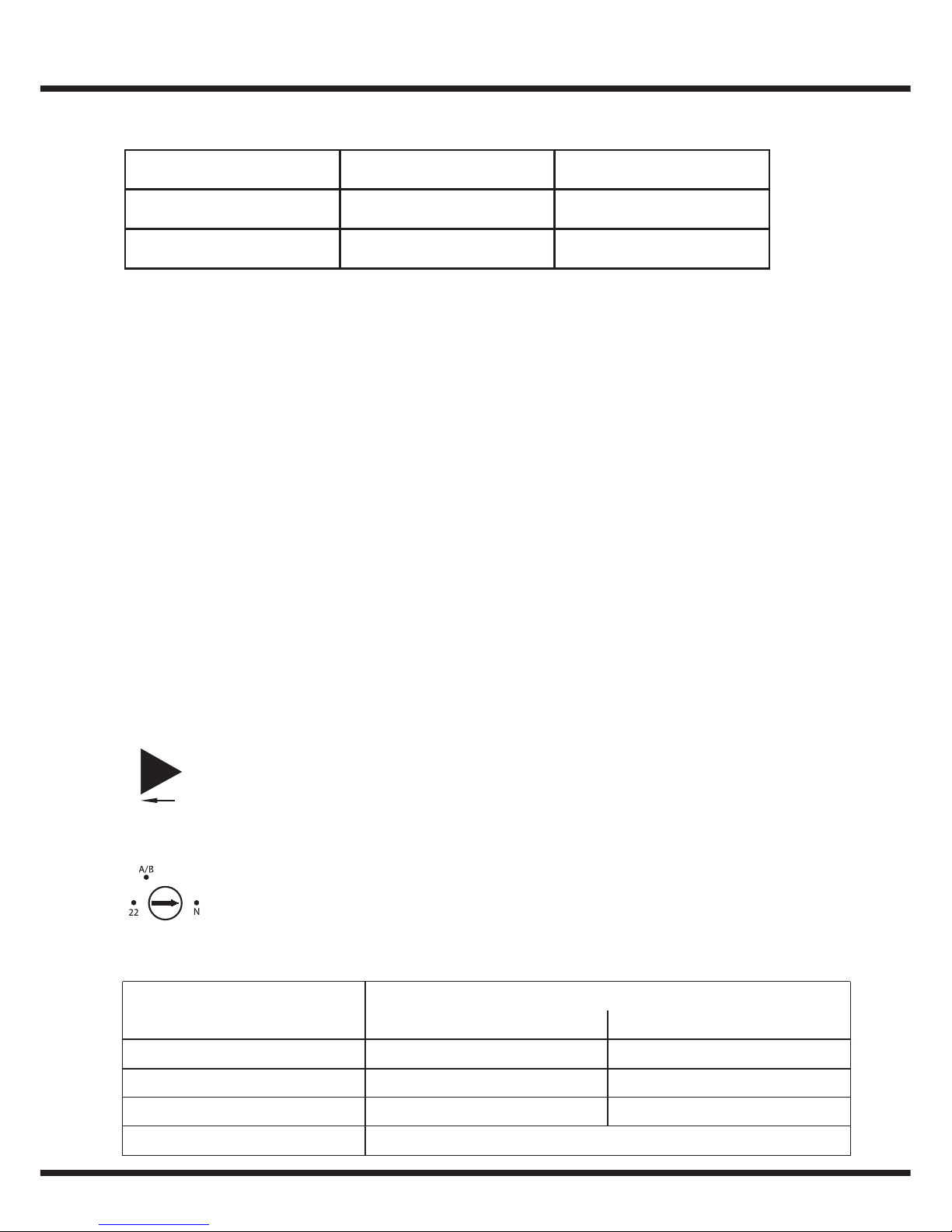
Mit dem für jeden Teilnehmerausgang ( A...F / A...H ) vorhandenen
Umschalter kann die Reaktion auf 22 kHz-Ton und TonBurst vertauscht
werden. In der Schalterstellung A/B werden die Satellitenpositionen
A und B vertauscht. Dadurch kann für einen Receiver, der nicht über
Steuersignale zum Orbitpositionswechsel verfügt, das Satellitensystem B
als Voreinstellung ausgewählt werden. Eine Betätigung des Schalters
wird sofort wirksam, jedoch muss die Programmwahl am Receiver
erneut erfolgen.
Beim Anschluss von nicht DiSEqC-tauglichen DVB-Receivern muss
der Schalter in Stellung „N=Band“ stehen!
SMS 9962 NF SMS 9982 NF
Terr.: 0 dB 0 dB
SAT: -3 ... +4 dB -3 ... +4 dB
Signal
14/18 V
0 kHz/22 kHz
TonBurst A / TonBurst B
DiSEqC
N=Band
vertikal/horizontal
low-Band/high-Band
SAT-System A/B
bleiben unbeeinflusst
22=Position
vertikal/horizontal
SAT-System A/B
low-Band/high-Band
“Receiver-Mode” Schalterstellung
B

• DiSEqC:
Die Multiswitche unterstützen DiSEqC 2.0, d.h. bidirektionale Kommunikation zwischen
Receiver und Multiswitch.
Der Betrieb des Multiswitches ist mit allen DiSEqC Receivern uneingeschränkt möglich
(einschließlich DiSEqC 1.0).
Der DiSEqC-Befehl "Standby" hat die gleiche Wirkung, als wenn keine Fernspeise-
spannung vom Receiver anliegt (siehe Standby-Funktion).
Sobald der Multiswitch DiSEqC-Befehle empfängt, werden alle analogen Schalt-
kriterien ignoriert.
Die DiSEqC-Adresse der Multischalter ist 14 Hex.
Die Ansteuerung entpricht der DiSEqC-Busspezifikation 4.2.
Stammleitungen ( SMS 99x2 NF ):
• Alle Stammleitungen (0...8 sind in jedem Fall mit den beiliegenden DC-festen
Abschlusswiderständen (ZFR 75 DC) abzuschließen!
• Bei allen Multiswitchen müssen nicht benutzte Stamm-Ein- / Ausgänge und
Teilnehmerausgänge (A...F / A...G) aus EMV-Gründen abgeschlossen werden.
Kaskadierbare Multiswitch-Verteiler SMK 99xx F:
Diese passiven Bauteile sind Ergänzungskomponenten der SMS-Multiswitche,
um eine Satelliten ZF-Verteilanlage aufzubauen. Sie unterstützen die
terrestrische Signalverteilung und sind rückwegtauglich !
Die Komponenten können bei zentraler Verteilung untereinander mit den
Steckverbindern ZSV 2 S direkt verbunden oder auch voneinander entfernt als
“Etagenverteilung” installiert werden.
Die Stammleitungsausgänge der Kaskadenkomponenten sind mit
Abschlusswiderständen ZFR 75 DC abzuschließen. Diese DC-entkoppelten
Abschlusswiderstände liegen den Multiswitchen SMS 99x2 NF bei.
In Abhängigkeit der Verteildämpfung können in Verbindung mit einem
SMS 99x2 NF typisch zwei, max. drei Multiswitch-Verteiler SMK 99xx F hintereinander
geschaltet werden. Zur Versorgung weiterer Teilnehmer / Receiver ist ein Kompakt-
Multiswitch SMS 99x2 NF als Nachverstärker einzusetzen. Die Kaskadenkomponenten
haben pro angeschlossenem Receiver eine Stromaufnahme von 25 mA.
Die Standby-Funktion der Multiswitche SMS 99x2 NF wird von den kaskadierbaren
Multiswitchen unterstützt!
Die Stammleitungen 0 und 2...8 können Fernspeiseströme bis 2 A durchlassen.
• Die SMK-Typen der Premium-Klasse (Endziffer 2) besitzen pro Teilnehmerausgang
einen “Receiver-Mode”-Umschalter (Beschreibung siehe Seite 4).
• Die SMK-Typen der Standard-Klasse (Endziffer 9) erfordern den Einsatz von DiSEqC-
tauglichen Receivern.
Kaskadierbare Multiswitch-Verteiler
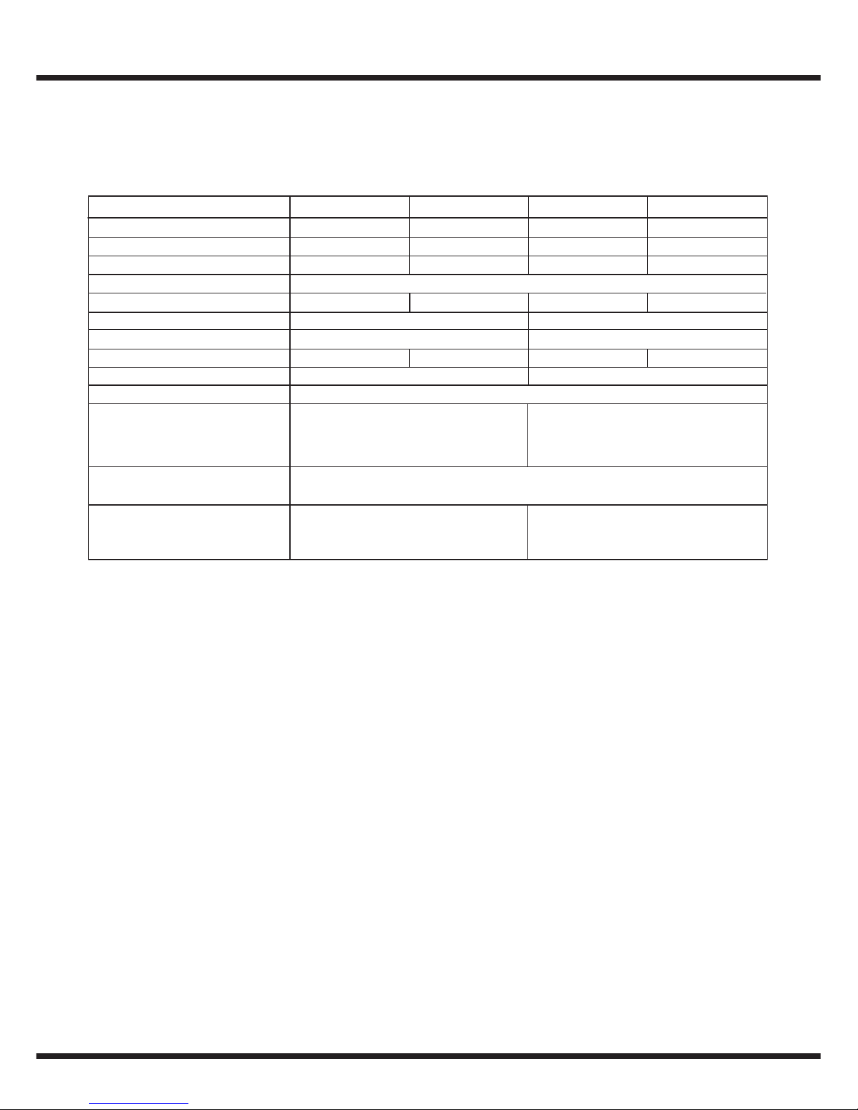
Technische Daten
DiSEqC ist ein Warenzeichen von EUTELSAT.
Technische Änderungen und Irrtümer vorbehalten.
Typ-Bezeichnung
Bestell-Nr.
Frequenzbereich
Anzahl der Teilnehmer
Durchgangsdämpfung Terr.:
Durchgangsdämpfung SAT:
Abzweigdämpfung Terr.:
Abzweigdämpfung SAT:
Strombedarf je
Teilnehmer (Receiver)
Abmessungen
Übersprechdämpfung V/H
Entkopplung:
Stamm/Stamm
Teilnehmer/Teilnehmer
>26 dB
max. 25 mA
B= 264 mm
H= 130 mm
T= 39 mm
B= 264 mm
H= 211 mm
T= 39 mm
SMK 9969 F
842382
6
3,5 ... 4,5 dB
2 ... 4,5 dB
16 ... 22 dB 17 ... 23 dB 20 ... 24 dB 21 ... 25 dB
812 16
3.5 ... 5 dB
4 ... 8 dB
21 ... 15 dB 22 ... 16 dB
1x 5...862 MHz / 8x 950 ... 2200 MHz
SMK 9989 F SMK 99129 F SMK 99169 F
842383 842409 842410
Typ-Bezeichnung
Bestell-Nr.
SMK 9962 F
842396
SMK 9982 F SMK 99122 F SMK 99162 F
842397 842398 842399
>30 dB
>30 dB
>26 dB
>26 dB

Technical advice
for the DiSEqC-multiswitches the Premium-Class
SMS 9962 NF and SMS 9982 NF
and for the cascadable multiswitches SMK 99xx F
!
Byk-Gulden-Str. 22 • D-78224 Singen
Telefon: +49 (0) 7731 - 86730 • Telefax: +49 (0) 7731 - 64202
SPAUN electronic confirms the keeping of the
EMC requirements in accordance to the
EU product norm EN 50083-2 and the keeping of
the safety requirements in accordance to the
EU product norm EN 50083-1 by the CE sign.
The multiswitches meet the more stringent
screening requirements according to EN 50083-2,
quality grade A.
All components are equipped with an earthing
terminal for connecting to the main potential
equalization.
Important: please observe the following
instructions !
Installation is only permitted in dry rooms and upon
a non-combustible surface. Ensure that there is
adequate air circulation. The permissible ambient
temperature range is: -20° C ... +50° C (253 K ...
323 K). Wall mounting only with power supply
housing on the left or on the right side
(horizontal mounting).
Select the correct LNB remote voltage.
Adjust the input levels for SAT IF if necassary.
Adjust the terrestrial input level.
Or switch the terr. amplifier off and bypass it.
Specifications and design are subject to change due to our policy of continual technical
improvement. 104990/10.04
Compact-multiswitches SMS 9962 NF und SMS 9982 NF
Useable
➜ as stand alone switch for 6 or 8 receivers,
➜ for extension with SMK 99xx F,
➜ as repeater amplifier or
➜ as end of line multiswitches.
Power supply
• The compact multiswitch has an internal energy-saving switch mode power supply.
The supply voltage range is: 100 V to 240 V, 50 ... 60 Hz
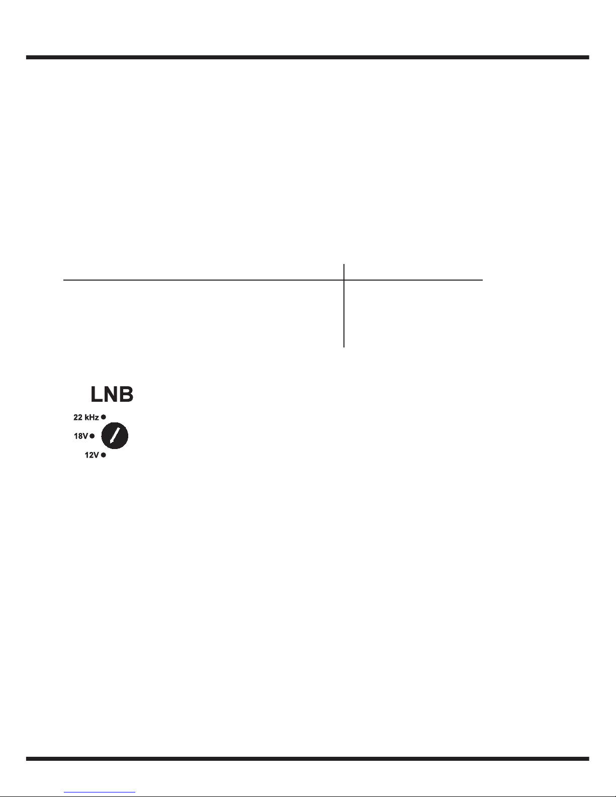
Remote power
The multiswitch supports 3 LNB-supply modes:
12 V: All 8 IF-inputs provide 12 Volts remote
voltage (mode for SMATV-LNBs).
18 V: The vertical IF-inputs provide 12 Volts,
the horizontal inputs provide 18 Volts
(mode for Twin-LNBs).
22 kHz: As 18 Volts mode, but high-band
inputs are modulated with 22 kHz
(mode for Universal-LNBs).
The selected LNB mode does not effect the
IF-selection logic.
• The total current load for the LNBs must not exeed 800 mA
(maximum 400 mA per connector).
Standby mode
• The multiswitch system supports a standby mode. The Sat-IF amplifiers and the LNB
remote voltage are only available when at least one receiver feeds a remote voltage to
its multiswitch outlet. The receiver voltage switches the 18 V from trunk and / or
to trunkline . Cascaded multiswitches activate upper devices via a control voltage on
trunkline .
• The rising remote voltage from the receiver causes a reset signal for the corresponding
DiSEqC microcontroller. The controller restarts in backwards compatible mode (see
analogue control signals).
• The terrestrial distribution is not effected by standby mode.
!
Power consumption (max): SMS 9962 / 9982 NF
SAT Standby terrestrial passive 3 W
terrestrial active 6 W
SAT active terrestrial passive 36 W
terrestrik active 40 W

Terrestrial
• The terrestrial input has an adjustable attenuator (SMS types 0 ... -15 dB).
The terrestrial amplifier is CATV-compatible (push-pull technique).
• Turning the adjustable attenuator fully CCW, the terrestrial amplifier is switched
off and bypassed (SMS 9962NF / SMS 9982 NF). Terrestrial distribution
then is completely passive and return-path compatible.
• Aerial signals must be fed via diplexers or multiband-amplifiers (selective multi-
bandamplifiers type MBV... / MVF... or selective FM devices as FM filter FMP 30 or
FM amplifier VFM.. F). It is not recommended to connect an aerial directly.
SAT IF distribution
• The IF amplifier units are equipped with a level adjuster for every IF input
to equalise different signal levels from the satellite systems. A level decrease up to
10 dB is possible.
• The max. input level is 90 dBµV for SMS 9962 NF and SMS 9982 NF (max. channel
occupation, level adjusters fully CCW).
• The IF signals must be connected as shown on the case of the multiswitch to ensure
correct access to the signals.
Max. outputlevel
• Trunklines (SMS 99x2 NF):
Multicarrier load:
•For multicarrier load the maximum output level must be derated in assistance with the
following table.
CSO
47-450 MHz 108 107 101 103
47-606 MHz 106 105 98 98
47-862 MHz 105 101 94 90
950-2200 MHz 109 35 dB IMA / EN 50083-3
950-2200 MHz 111 35 dB IMA / EN 50083-3
Range
A: 19 K
C: 29 K
E: 42 K
94
––
––
92
––
––
dBµV / 60 dB / EN 50083-3
IMA3IMA2CTB CENELEC-
Raster
dBµV / 1R8-15
BK-Raster 36TV/24FM
CTB/72dB CSO/69dB
––
––
98
––
––
93
dBµV /
CTB/60dB
1TR8-1
CSO/60dB
28 analog + 63 digital
3
2
Number of
carriers
2 4 6 8 10 12 16 24 36
Number of
amplifiers
123456812 18
Level reduction
( dB )
035678911 12

Receiveroutputs (SMS 99x2 NF)
• Tap loss
Selection logic
•The selection logics of different taps are totally independent and can be controlled by
either the known analogue control signals or DiSEqC signals.
•Switching is backwards compatible with the analogue control signals until a valid
DiSEqC command is received. Analogue control signals will be ignored afterwards until
a reset is done (interruption of the remote voltage or interruption of mains power or
DiSEqC command 'Reset'). Mixed use of DiSEqC and non DiSEqC receivers is possi-
ble at the same tap when the remote voltage is interrupted when changing the recei-
ver.
•Analogue control signals:
- 14 V/18 V polarity selection (vertical/horizontal)
- 0 kHz/22 kHz band selection (low/high band)
- ToneBurst satellite selection (Satellite A/B)
•DiSEqC control signals:
Polarity vertical/horizontal
Band low band/high band
Position A (east)/B (west)
A mode selector for every receiver output (A...F/A...H) is present.
With this selector the reaction to 22 kHz tone and ToneBurst may be
swapped to change the sat-system with the 22 kHz tone. The switch
position A/B swaps the satellite positions A and B. In this mode
the satellite B is the default satellite system. (Necessary for receivers
without position control signals.) A manipulation of the switch beco-
mes immediately effective. The receiver program has to be selected
again. In case of a connected non DiSEqC DVB-receiver the selector
must be in '22' mode!
SMS 9962 NF SMS 9982 NF
Terr.: 0 dB 0 dB
SAT: -3 ... +4 dB -3 ... +4 dB
Signal
14/18 V
0 kHz/22 kHz
ToneBurst A / ToneBurst B
DiSEqC
N=Band
vertical/horizontal
low-Band/high-Band
SAT-System A/B
uneffected
22=Position
vertical/horizontal
SAT-System A/B
low-Band/high-Band
“Receiver-Mode” Selection
B

• DiSEqC:
The multiswitches support DiSEqC level 2.0. Bi-directional communication with the
receiver is possible.
The multiswitches can be controlled by every DiSEqC receiver (including DiSEqC 1.0).
The DiSEqC 'Standby' command is supported. Same effect as if no remote voltage
from receiver is detected. When the multiswitch receives a valid DiSEqC command all
analogue control signals will be ignored until a reset is done.
The DiSEqC address is 14 Hex.
DiSEqC is implemented according to DiSEqC Bus Specification 4.2.
Trunklines ( SMS 99x2 NF ):
• All trunklines (0...8) have to be terminated with the isolated terminations (ZFR 75 DC)
supplied.
• Unused inputs and taps (A...F / A...H) must be terminated, -EMC conformity.
Cascadable multiswitches SMK 99xx F:
These passive modules are accessory components for the multiswitches for con-
structing a satellite IF distribution system. They support the terrestrial signal
distribution and are fully return path compatible.
In the case of central distribution, the components can be connected to one another
with ZSV 2 S push-on connectors, or they may also be installed separated from one
another as "storey distributors".
The trunklines of the cascade have to be terminated with DC-isolated resistors
(ZFR 75 DC). These DC isolated resistors are supplied with the SMS-multiswitches.
As a rule, typically 2, max. 3 cascadable multiswitches can be connected one behind
the other. A network repeater amplifier (e.g. type SMS 99x2 NF) should be used in
order to subsequently install additional distributors. The cascade components have a
current consumption of 25 mA per connected receiver.
The stand-by function of the multiswitches is supported by the cascadable
multiswitches.
The trunklines 0 and 2...8 can transmit remote feeding currents up to 2 A.
• The mode selectors, described under “Selection logic” are available in the
SMK 99xx2 F types.
• The SMK 99xx9 F types require DiSEqC compatible receivers.

Type designation
Order no.
Frequency range
Number of subscribers
Through loss, Terr.:
Through loss, SAT:
Tap loss, Terr.:
Tap loss, SAT:
Current requirements per
receiver
Dimensions
Switching isolation
Isolation:
- Trunkline/Trunkline
- Tap/Tap
>26 dB
max. 25 mA
B= 264 mm
H= 130 mm
T= 39 mm
B= 264 mm
H= 211 mm
T= 39 mm
SMK 9969 F
842382
6
3,5 ... 4,5 dB
2 ... 4,5 dB
16 ... 22 dB 17 ... 23 dB 20 ... 24 dB 21 ... 25 dB
812 16
3.5 ... 5 dB
4 ... 8 dB
21 ... 15 dB 22 ... 16 dB
1x 5...862 MHz / 8x 950 ... 2200 MHz
SMK 9989 F SMK 99129 F SMK 99169 F
842383 842409 842410
Type designation
Order no.
SMK 9962 F
842396
SMK 9982 F SMK 99122 F SMK 99162 F
842397 842398 842399
>30 dB
>30 dB
>26 dB
>26 dB
Cascadable multiswitches
Technical data
DiSEqC is a trademark of EUTELSAT.
Whilst every effort has been made to provide accurate information, no responsibility is accepted for errors or
omissions.
This manual suits for next models
1
Table of contents
Languages:
Other Spaun Electronic Switch manuals

Popular Switch manuals by other brands

3Com
3Com SUPERSTACK II 2000 TR Guide

Dahua Technology
Dahua Technology DH-PFS5936-24GF8GT4XF quick start guide

ZyXEL Communications
ZyXEL Communications GS2220 Series user guide

Resol
Resol TS10 manual

Secure
Secure SSR 302 User and installation instructions

Moxa Technologies
Moxa Technologies ToughNet TN-5524-8PoE-P24-T Quick installation guide


Korenix
Korenix JetNet 3212G-2C2F user manual

Magnetrol
Magnetrol Thermatel TD1 Installation and operating manual

Eaton
Eaton NZM3-XTVD-HS Instruction leaflet

Siemens
Siemens SIMATIC NET RUGGEDCOM RS900 installation manual

Allied Telesis
Allied Telesis AT-9000/24 datasheet

Microsoft
Microsoft MN-150 user guide